
A destructive test (DT) takes a sample to fracture, to permanent deformation or to an indentation in order to measure properties such as strength, ductility and toughness; a non-destructive test (NDT) inspects the part without impairing its use, looking for cracks, pores and other discontinuities. One measures a property by sampling, because the sample is lost; the other checks integrity and can be applied to 100% of the parts, including in service. Neither replaces the other: qualifying a welding procedure to ISO 15614-1:2017 requires both on the same test specimen.
This article compares the two groups and shows the role of each in quality control: what each destructive test measures (with a link to the dedicated article for each one), why hardness sits on the boundary, how NDT methods work and where they fall short, which standards govern inspection and personnel certification and, as a complete case, the test plan for a welded joint in a steel structure, from qualification to production.
In short:
- Destructive: tensile, compression, flexural, bend, impact, hardness, fatigue, creep, macrography. Gives a property value and applies to the lot by sampling.
- Non-destructive: visual, liquid penetrant, magnetic particle, ultrasonic, radiographic, eddy current, acoustic emission, thermography, leak testing. Gives an indication, compared with an acceptance criterion.
- NDT standards: personnel are certified to ISO 9712:2021 (ABNT NBR NM-ISO 9712:2025 in Brazil); for welds, ISO 17635:2025 guides the choice of method.
- In practice: destructive testing to qualify material and process; NDT to check every part produced and to monitor equipment in operation.
What destructive and non-destructive testing are
The division is based on the integrity of the part after the test. In a destructive test, a test specimen is loaded until it fractures, deforms permanently or receives an indentation, and what is read is the material's response to that load: the maximum force, the elongation, the absorbed energy, the number of cycles to failure. Since the specimen does not return to service, the result does not describe the part that was tested, but the lot it came from. That is why destructive testing is always done by sampling, and it is only valid if the sample represents the lot: same heat, same heat treatment, same sampling location (Garcia, Spim and Santos, Ensaios dos Materiais, 2nd ed., LTC, 2012).
In a non-destructive test, the part is examined using a physical phenomenon that does not alter it: light, capillary action, magnetic fields, ultrasonic waves, ionizing radiation, induced electric currents, heat. The goal is to find and size discontinuities, that is, interruptions in the continuity of the material such as a crack, pore, inclusion or lack of fusion, or to measure a thickness. Since the part stays intact, NDT can inspect every part produced and monitor a piece of equipment throughout its life. The group is called NDT (non-destructive testing) or NDE (non-destructive examination), and the terminology of the field is in ASTM E1316; destructive testing is called DT (destructive testing).
The essential difference fits in one sentence: destructive testing measures properties, non-destructive testing looks for defects. An ultrasonic test can state that a weld has no pores above a certain size, but it does not tell you its tensile strength; a tensile test gives you the strength, but only of the specimen that fractured. That is why the two coexist in any serious quality system. The overview of all test families, including chemical and metallographic ones, is in the article on materials testing.
Difference between destructive and non-destructive testing
The difference between destructive and non-destructive testing lies in what each one delivers: destructive testing measures a property of the material and sacrifices the sample; non-destructive testing checks the integrity of a specific part and returns it to service. Beyond "breaks or does not break", six practical differences decide which test goes into each stage:
- What you get. Destructive testing delivers a property value with a unit: MPa, J, HBW, number of cycles. NDT delivers an indication, which is the response of the method (an echo on the screen, a shadow on the film, a penetrant mark), to be interpreted and compared with an acceptance criterion.
- How many parts. Destructive testing works with samples per lot; NDT can reach 100% of the parts and repeat the inspection in service.
- Cost. In destructive testing, the sample is lost and you pay for machining the specimen; when the part is unique or expensive, this makes testing the part itself unfeasible. In NDT, the part is not lost, but the cost lies in the equipment, the inspection time per part and the certified personnel.
- What ensures confidence in the result. In destructive testing, the verified machine (force to ISO 7500-1, with an accuracy class for the load cell) and a specimen that conforms to the standard; when the report must be valid for third parties, a laboratory accredited to ISO/IEC 17025:2017 (in Brazil, by Cgcre, the accreditation body of Inmetro, Brazil's national metrology institute). In NDT, above all the operator: interpretation depends on who performs it, which is why personnel are certified by method and level to ISO 9712.
- Nature of the result. Destructive testing answers "how much": how much the material withstands, elongates, absorbs. NDT answers "where and how large" a discontinuity is, and whether it is acceptable.
- Standards. In destructive testing, the method standard (ISO 6892-1 for tensile, ISO 148-1 for Charpy). In NDT, the method standard, the acceptance standard and the personnel certification standard.
In the photo, the two ways to evaluate a welded joint: on the left, ultrasonic testing inspects the weld bead without damaging the plate; on the right, specimens cut from a joint have been bent and fractured, and do not return to service.
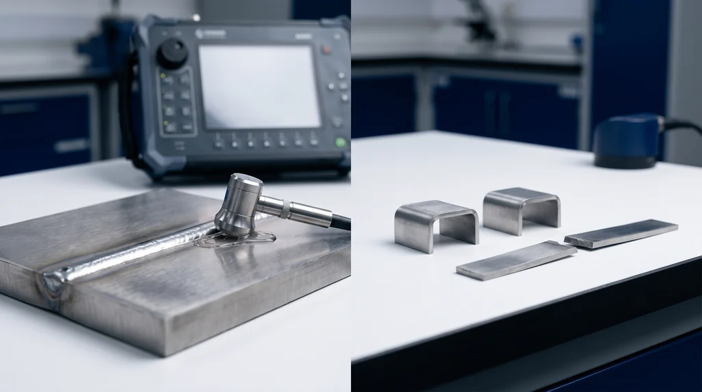
The table summarizes the comparison:
| Criterion | Destructive testing | Non-destructive testing (NDT) |
|---|---|---|
| Purpose | measure a material property | detect and size discontinuities |
| Does the part return to service? | no: fractured, cut or indented | yes |
| Coverage | samples per lot | up to 100% of parts, including in service |
| Result | value with a unit (MPa, J, HBW) | indication compared with an acceptance level |
| Confidence in the result | verified machine (ISO 7500-1) and specimen per the standard | certified operator (ISO 9712) and qualified procedure |
| Typical standards | ISO 6892-1, ISO 148-1, ISO 6506-1, ISO 5173 | ISO 17637, ISO 3452-1, ISO 9934-1, ISO 17636-1, ISO 17635 |
The role of each in quality control
In a quality system, the two groups answer different questions at different moments in the life of the product. Destructive testing answers the question "does this material, made by this process, have the required properties?". It appears in qualification (of a material, a welding procedure, a welder, with the weld test specimen), in lot acceptance by sampling, in product development and in failure analysis. Once the process is qualified, there is no need to break every part: it is enough to keep the process under control and repeat the test at the frequency required by the product standard.
NDT answers the question "did this specific part come out free of defects?". Even with a qualified process, each part may have a pore, a lack of fusion or a crack that the sampling test did not catch, because the fractured sample was not that part. That is why NDT comes in during production, part by part or to the extent defined by the design, and during maintenance, when equipment in operation is reinspected to detect fatigue cracks or wall thinning due to corrosion.
When the part is critical and cannot be cut, such as a large shaft, a pressure vessel or a one-off casting, the classic solution combines both: the destructive test is performed on a witness specimen taken from the same lot, the same heat and with the same heat treatment, and the part receives 100% NDT. The witness specimen ensures the property; NDT ensures the integrity of that part. The role of these tests in the quality management system is covered in the article on quality engineering.
Types of destructive tests
Each destructive test applies one type of load and measures the property that load reveals. The choice follows the loading of the part in service. Below, each one in a few lines, with the article that covers it in detail; the complete list, with what each test measures and the machine for each one, is in the guide to the main mechanical tests.
- Tensile: pulls the specimen until fracture and records force and elongation, which become the stress-strain curve. From it come the modulus of elasticity, the yield strength, the ultimate tensile strength and the elongation. See the tensile test, the standard for metals in ASTM E8 and ISO 6892-1 and the one for plastics in ASTM D638.
- Compression: crushes the specimen between parallel platens. It is the decisive test for brittle materials such as concrete and mortar, and the main example of control by sampling in civil construction, with cylinders cast from each batch of concrete (NBR 5739, the Brazilian standard for concrete compression testing). See the compression test.
- Flexural: loads a simply supported bar in 3 or 4 points and measures flexural strength and modulus. It is preferred for ceramics, plastics and materials that are hard to hold in a grip, such as the mortar prisms of NBR 13279 (the Brazilian standard for flexural and compressive strength of mortar). See the flexural test.
- Bend: bends the specimen around a mandrel to a fixed angle and checks whether the tensioned face cracks. It does not give a strength value: the result is pass or fail, which is why it is the ductility test for welds and for rebar to NBR 7480 (the Brazilian standard for steel reinforcing bars). See the bend test.
- Impact (Charpy): a pendulum fractures a notched specimen in a single blow, and the absorbed energy measures notch toughness. Performed at several temperatures, it shows the ductile-to-brittle transition of steel. See the impact test.
- Hardness: measures resistance to penetration by a standardized indenter (Brinell, Vickers, Rockwell). It leaves a permanent indentation, and it is the boundary case of the classification, covered in the next section. See the hardness test.
- Fatigue: applies cyclic loading until fracture and produces the S-N curve, which relates stress amplitude to the number of cycles. It explains why parts fail at stresses well below the yield strength. See the fatigue test.
- Creep: holds a constant load at elevated temperature for hours or months and measures deformation over time and time to rupture. It is the test for boiler and turbine components. See the creep test.
- Shear, torsion and cupping: measure, respectively, the shear strength of fasteners and joints, the behavior of shafts and wires under torque, and the formability of sheet metal. See the shear test, the torsion test and the cupping test.
- Macrography and metallography: cut, grind, polish and chemically etch a section of the part. In welds, macrography (etching per ISO 17639) reveals the fusion line, the heat-affected zone, the passes and the penetration; micrography shows the phases and grain size. They are destructive because they require cutting the part.
- Component and prototype tests: instead of a machined specimen, the part itself or the assembly is tested, at full scale, until failure or until the required life. Examples include the burst test of a vessel or pipe, fatigue testing of an automotive component, drop and fatigue testing of a landing gear in aircraft certification, and the crash test of a vehicle. A pressure test that only checks leak tightness or strength, without taking the part to rupture, is something else: it is a proof test, and the part returns to service.
Hardness: destructive or non-destructive?
Hardness is a material's resistance to indentation by a harder body, and the test that measures it is the most common point of doubt in this classification, because sources disagree. Strictly speaking, the test is destructive: the indenter leaves a permanent impression on the surface. In a specimen that has been cut and mounted, as in the hardness profile of a welded joint, the sample is lost just as in any other destructive test. In a large part, however, a Brinell impression 2.4 to 6 mm in diameter (with a 10 mm ball) or a Vickers impression a few tenths of a millimeter across rarely affects function, and the part goes into service. That is why some of the literature calls the test "semi-destructive" and why portable hardness testers exist for measuring assembled parts (ASTM E10 covers portable Brinell machines). Even so, hardness testing is not an NDT method: ISO 9712 does not include it among its ten methods, and it measures a property rather than looking for defects.
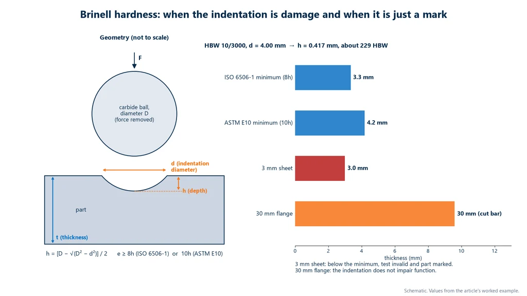
What decides whether the impression is just a mark or damage is the thickness of the part and the function of the surface. ISO 6506-1:2014 requires a thickness of at least 8 times the depth of the Brinell impression, and ASTM E10-23 recommends 10 times, with no visible mark on the opposite side. The depth comes from the geometry of the spherical cap: h = [D − √(D² − d²)] / 2, where D is the ball diameter and d is the impression diameter. Below the minimum thickness, the test is invalid (the reading is influenced by the support) and the part is marked. And on a functional surface, such as a bearing raceway or a sealing face, any impression can cause the part to be rejected, even if the thickness is large.
Worked example: flange or thin plate?
An HBW 10/3000 test (ball D = 10 mm, force F = 29,420 N) leaves an impression with a mean diameter d = 4.00 mm. What is the hardness, and can the test be done on a 30 mm flange and on a 3 mm plate?
- √(D² − d²) = √(100 − 16) = √84 = 9.165 mm; therefore D − √(D² − d²) = 0.835 mm.
- Depth: h = 0.835 / 2 = 0.417 mm.
- Hardness: HBW = 0.102 × 2 × 29,420 / (π × 10 × 0.835) = 6,001.7 / 26.23 ≈ 229 HBW. The ratio d/D = 0.40 is within the 0.24 to 0.6 range required by ISO 6506-1.
- Minimum thickness: 8 × 0.417 = 3.3 mm per ISO 6506-1; 10 × 0.417 = 4.2 mm per ASTM E10.
- Conclusion: on the 30 mm flange, the impression is a 4 mm mark that does not affect function, and the test is, in practice, non-destructive. On the 3 mm plate, the thickness is below the minimum of both standards: the result is not valid and the plate is left marked. There, the way forward is a scale with shallower indentation, such as Vickers or superficial Rockwell.
The diagram below shows the geometry of the impression, not to scale, and compares the minimum thicknesses from the example with the plate and the flange. The red bar, for the 3 mm plate, falls below both minimums.
Types of non-destructive testing (NDT)
Each NDT method is based on a physical phenomenon, and that phenomenon defines three things: which discontinuity it can see, at what depth, and in which material it works. No method does everything, which is why an inspection plan almost always combines a surface method with a volumetric one. ISO 9712:2021 recognizes ten methods for personnel certification: acoustic emission, eddy current, leak testing, magnetic testing, penetrant testing, radiographic testing, strain gauge testing, thermographic testing, ultrasonic testing and visual testing. Nine of them look for discontinuities; in the order in which they usually appear in an inspection plan, they are:
- Visual (VT): the eye, with or without a magnifier, mirror, borescope or weld gauge. It always comes first: it reveals surface-breaking cracks, undercut, spatter, and the profile and dimensions of the weld bead. It depends on lighting and access, and it only sees the surface. For fusion welds, the procedure is in ISO 17637.
- Liquid penetrant (PT): a low-viscosity liquid, colored or fluorescent, enters discontinuities by capillary action; once the excess is removed, a developer draws the liquid back out and outlines the crack. Per ISO 3452-1:2021, it detects cracks, laps, porosity and lack of fusion open to the surface, in metals and other materials that are not excessively porous. It sees nothing closed or internal and does not measure crack depth.
- Magnetic particle (MT): the part is magnetized, and a crack deflects the flux, creating a leakage field that gathers iron particles applied dry or in suspension. It detects surface and near-surface discontinuities, but only in ferromagnetic material: it does not work on austenitic stainless steel, aluminum or copper (ISO 9934-1:2016). The field must cross the crack: the standard considers detection effective up to about 60° from the optimum direction, which is why the part is magnetized in two perpendicular directions.
- Ultrasonic (UT): a probe emits high-frequency mechanical waves that travel through the part and reflect at interfaces: the back wall and any internal discontinuity. The round-trip time of the echo gives the depth of the reflector, and the amplitude helps size it. It detects planar and volumetric defects in the interior and measures thickness with access from one side only. It requires couplant, calibration on the right material and a qualified operator; coarse-grained materials, such as castings and austenitic welds, scatter the wave and make interpretation difficult. Variants such as phased array and TOFD extend coverage.
- Radiography and gamma radiography (RT): X-rays or gamma rays pass through the part and record, on film or a digital detector, differences in thickness and density. It is excellent for volumetric defects (pores, slag inclusions, lack of penetration) and leaves a permanent record. A tight crack parallel to the beam, however, may not show up, which is why radiography and ultrasonics complement each other. It requires access from both sides and involves ionizing radiation, regulated in Brazil by CNEN (the Brazilian National Nuclear Energy Commission).
- Eddy current (ET): an alternating-current coil induces electrical currents in the part; surface cracks and variations in conductivity or coating thickness change the coil impedance (García-Martín, Gómez-Gil and Vázquez-Sánchez, Sensors, 2011). It works only on conductive material and to a limited depth, because the currents concentrate near the surface. It is widely used on heat exchanger tubes and for alloy sorting.
- Acoustic emission (AT): sensors pick up the waves emitted by a crack that grows while the structure is loaded, for example during a pressure test of a vessel. It locates what is active but does not size it: the indicated region then goes to ultrasonic or magnetic particle testing.
- Thermography (TT): an infrared camera measures the temperature field on the surface. It reveals delaminations and disbonds in composites and hot spots in electrical panels, with limited depth and sensitivity to surface emissivity.
- Leak testing (LT): detects leaks by bubble, pressure change, vacuum or tracer gas (helium). It shows that there is a leak path, not what the structural defect is. ISO 9712 excludes hydrostatic pressure testing from this method.
The tenth ISO 9712 method, strain gauge testing, is different from the others: it measures strain in a loaded structure without looking for defects. Other techniques, such as ACFM and phased array, are also certified in Brazil by ABENDI (the Brazilian Association of Non-Destructive Testing and Inspection).
The diagram below brings these limitations together on a welded joint. On the left, a cross-section of the weld with five typical discontinuities, from a surface-breaking crack to an inclusion in the interior; on the right, which zones each method reaches and which material it works on. Surface methods (visual, PT, MT, ET) are in the first column; volumetric methods (UT, RT), in the last two.
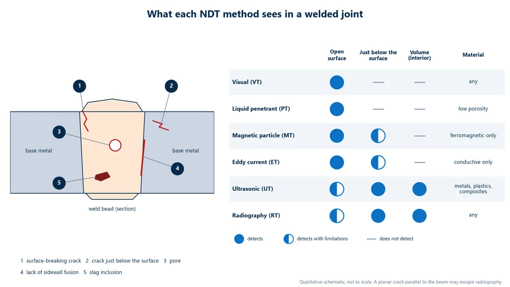
The table summarizes the most widely used methods:
| Method | What it detects | Material | Main limitation |
|---|---|---|---|
| Visual | surface-breaking discontinuities, weld bead geometry | any | accessible surface only |
| Liquid penetrant | discontinuities open to the surface | metals and low-porosity non-metals | cannot see closed or internal defects |
| Magnetic particle | surface and near-surface | ferromagnetic only | field must cross the crack |
| Eddy current | surface cracks, conductivity, coating | conductive only | shallow depth |
| Ultrasonic | internal defects, thickness | metals, plastics, composites | couplant, coarse grain, operator |
| Radiography | volumetric defects | any | radiation, crack parallel to the beam |
| Acoustic emission | active crack under load | metals, composites | does not size |
When people ask which are the three most common types of NDT in industry, the answer is usually ultrasonic (internal defects), liquid penetrant (surface-breaking defects) and magnetic particle (surface and near-surface, in ferromagnetic steel), always preceded by visual inspection. Radiography completes the basic set for welds and castings.
NDT standards and personnel qualification
There is no single NDT standard. There are three layers: the standard that certifies who performs the test, the standard for each method, and the standard (or code) that says which method to apply and what to accept.
Personnel. ISO 9712:2021 (5th edition) sets the requirements for qualification and certification of personnel in the ten methods listed above, at three levels: Level 1 performs tests following instructions, Level 2 sets up the equipment, performs tests and interprets them according to the procedure, and Level 3 writes procedures and is technically responsible for the method. In Brazil, the standard was published as ABNT NBR NM-ISO 9712 in April 2025, identical to ISO 9712:2021. Certification is carried out by ABENDI's National Qualification and Certification System (SNQC), in operation in Brazil since 1991 and recognized under the ICNDT multilateral agreement. The method standards themselves refer to it: ISO 3452-1 recommends that penetrant testing personnel be certified to ISO 9712 or an equivalent scheme.
Methods. Each method has its own procedure standard. For welds, the most cited are ISO 17637 (visual), ISO 3452-1 (liquid penetrant), ISO 9934-1 (magnetic particle), ISO 17636-1 and ISO 17636-2 (radiography with film and with digital detectors) and ISO 17640 (ultrasonic). Acceptance of indications comes from other standards, such as ISO 11666 for ultrasonic testing and the ISO 10675 series for radiography, linked to quality levels B, C and D of ISO 5817, from most to least stringent.
Selection. ISO 17635:2025 gives the general rules for NDT of welds in metallic materials: how to choose the method and testing level according to the required quality level, the material, the thickness, the welding process and the extent of inspection. It replaced the 2016 edition, withdrawn in April 2025. For pressure vessels and boilers governed by the ASME code, methods and procedures are in Section V of the BPVC (2025 edition), and for steel structures, AWS D1.1/D1.1M:2025 covers qualification, fabrication and inspection.
Radiation. Industrial radiography in Brazil follows standard CNEN NN 6.04 (CNEN Resolution 145/2013, issued by the Brazilian National Nuclear Energy Commission): the facility needs a license, a certified radiation protection supervisor and registered operators. Hiring gamma radiography from a provider that does not meet these requirements exposes the contracting company.
How the two complement each other: test plan for a welded joint
The welded joint of a steel structure is the best example of how the two groups divide the work. Before production, the welding procedure is qualified once: a test coupon is welded with the proposed parameters (process, consumable, position, preheat), and it is shown to produce sound joints with the required mechanical properties. ISO 15614-1:2017 states that this is the purpose of qualification. Per the standard's test table, a full-penetration butt joint in plate receives, at level 2:
- 100% NDT on the test coupon: visual, radiographic or ultrasonic, and surface crack detection (magnetic particle, or liquid penetrant on non-magnetic material). NDT comes first, to make sure the coupon is sound before it is cut.
- Destructive tests on the specimens taken from it: 2 transverse tensile tests, 4 transverse bend tests, 2 sets of Charpy impact tests (3 specimens each, in the weld metal and in the heat-affected zone), hardness and 1 macro examination.
At level 1, which is less demanding, visual inspection, the 2 tensile tests and the 4 bend tests are sufficient. When the contract does not specify the level, level 2 applies.
The acceptance criteria for the destructive tests, in summary, are as follows. In the transverse tensile test, the tensile strength must not be lower than the specified minimum of the parent metal. In the bend test, performed per ISO 5173, no imperfection may exceed 3 mm in any direction; in plate less than 12 mm thick, 2 root bends and 2 face bends are used, and from 12 mm upward all 4 can be side bends. In the Charpy test, the average of each set of 3 must reach the required value, and a single value may fall below it as long as it is not less than 70% of that minimum. The macro examination, with etching per ISO 17639, documents the joint cross-section (fusion line, heat-affected zone, passes) for the assessment of imperfections. Once everything passes, the result becomes the welding procedure qualification record (WPQR), and the procedure can be used on the job.
In production, nobody cuts the structure. Each joint receives 100% visual inspection (ISO 17637) and volumetric or surface NDT to the extent defined by the design or application standard, selected per ISO 17635. In service, NDT returns periodically: visual inspection, magnetic particle testing at stress concentration points, where fatigue cracks initiate, and ultrasonic thickness measurement where there is corrosion.
The flowchart below summarizes the three phases. In orange, the destructive tests, which only appear in qualification; in blue, NDT, which runs through all three.
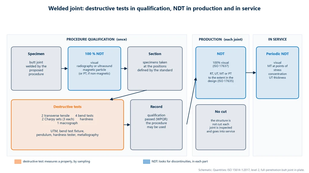
The logic of the flowchart is the same in other sectors. In civil construction, concrete cylinders broken on a sampling basis verify the strength of the batch, while the cast element itself is not broken. In rebar manufacturing, tensile and bend tests per lot verify the steel grade. Destructive testing qualifies; NDT, or the inspection of each part, verifies.
When to use destructive testing and when to use NDT
Use destructive testing when the question is about a property of the material or the process, and NDT when the question is about the integrity of a specific part. In practice, the choice comes from four questions, in this order:
- Do I need a property, or do I need to know whether there is a defect? Strength, yield, elongation, toughness and fatigue life can only be measured with destructive testing. Cracks, porosity, lack of fusion and wall thinning are found with NDT.
- Can the part be sacrificed? If it cannot (a one-off, expensive or already assembled part), the destructive test is done on a witness test specimen from the same lot, and the part itself receives NDT.
- Is it a lot or an individual part? To accept a lot, destructive testing by sampling is enough, provided the sample is representative. To guarantee every part, only 100% NDT gives the answer.
- Is the part in service? In operation, the route is periodic NDT. Destructive testing of in-service parts only happens in failure analysis, when the part has already failed or been removed.
In failure analysis, the order matters: you start with the least destructive method (visual inspection, NDT on sister parts) and only then cut the part, so as not to destroy evidence that a later test would need. This sequence is described in detail in the article on materials testing.
Applications by industry
In every industry, destructive tests appear in the qualification of the material and the process, and non-destructive tests appear in manufacturing and maintenance; what changes from one industry to another is which tests dominate. In civil construction, control is mainly destructive and by lot: concrete cylinders broken in compression and steel bars tested in tension and bending. In oil and gas and pressure vessels, the weight is on NDT of welds and wall thickness, because the equipment stays in service for decades. In aerospace, both extremes coexist: full-scale destructive testing of components for certification, and scheduled non-destructive inspection of every aircraft, because a fatigue crack at a rivet hole must be found before it grows.
The table brings together the most typical tests in each industry:
| Industry | Typical destructive tests | Typical NDT |
|---|---|---|
| Civil construction | compression of concrete and mortar test specimens; tensile and bend testing of rebar | visual; rebound hammer and ultrasonic testing of hardened concrete |
| Oil, gas and pressure vessels | tensile, bend and Charpy tests in weld qualification; prototype burst test | radiographic and ultrasonic testing of welds; ultrasonic thickness measurement; magnetic particle testing; hydrostatic test |
| Aerospace | full-scale fatigue and drop testing of components; tensile testing of alloys and composites | eddy current testing of holes and rivets; ultrasonic testing and thermography of composites |
| Automotive | tensile and cupping tests of sheet metal; component fatigue; crash test | visual; eddy current part sorting; leak testing |
| Power generation | creep and elevated-temperature tensile tests of boiler and turbine steels | ultrasonic testing; acoustic emission; thermography of electrical panels |
Worked examples
The three examples below apply the criteria covered in welded joint qualification and the principle of ultrasonic testing. The requirement values are hypothetical, for the example; in a real qualification, they come from the base metal specification.
Example 1: transverse tensile test of a welded joint
A transverse test specimen taken from plate with thickness t = 12 mm and gauge width b = 25 mm fractured at a maximum force Fm = 165 kN. The base metal is a steel with a specified minimum tensile strength of 400 MPa (such as ASTM A36, 400 to 550 MPa). Does the joint pass?
- Original area: S0 = t × b = 12 × 25 = 300 mm².
- Strength: Rm = Fm / S0 = 165,000 N / 300 mm² = 550 MPa.
- Criterion: Rm ≥ base metal minimum; 550 ≥ 400 MPa. Pass, and the second test specimen must pass as well.
- Machine: 165 kN calls for a 200 kN machine, such as the MBIOII-200-M2, with 200 kN wedge grips. A 300 kN machine can also run the test; a 100 kN machine cannot.
Example 2: Charpy criterion (average and 70%)
The base metal requirement is 27 J (hypothetical). Two sets of 3 test specimens gave: set A, 31, 26 and 20 J; set B, 32, 30 and 20 J. Which one passes?
- Minimum individual value allowed: 0.70 × 27 = 18.9 J.
- Set A: average = (31 + 26 + 20) / 3 = 77 / 3 = 25.7 J, below 27 J. Fail on the average, even though no individual value is below 18.9 J.
- Set B: average = (32 + 30 + 20) / 3 = 82 / 3 = 27.3 J ≥ 27 J, and the lowest value, 20 J, is higher than 18.9 J. Pass.
The example shows that the criterion has two independent conditions: a set can fail on the average without any single bad value.
Example 3: depth of a reflector in ultrasonic testing
With a straight-beam probe (longitudinal wave) on a carbon steel part, sound velocity v = 5,920 m/s, the echo of an indication appears at t = 6.0 µs (round trip). At what depth is the reflector?
- In pulse-echo, the wave travels the path twice: d = v × t / 2.
- d = 5,920 m/s × 6.0 × 10⁻⁶ s / 2 = 0.03552 m / 2 = 0.01776 m ≈ 17.8 mm.
- If the instrument is calibrated for carbon steel and the part is austenitic 302 stainless steel (about 5,740 m/s), the actual depth would be 5,740 × 6.0 × 10⁻⁶ / 2 = 17.2 mm: an error of about 3%. That is why ultrasonic equipment is calibrated on a block of the same material as the part.
The velocities are table values from manufacturers (Olympus, Elcometer) and vary with composition, microstructure and temperature.
How to interpret: questions from those who use the results
The points below are the ones that most often lead to wrong decisions in receiving inspection, in-service inspection and qualification.
Are indication, discontinuity and defect the same thing?
No, and the difference is the basis of every NDT report. Under the ASTM E1316 terminology, an indication is the response of the method (the echo, the shadow, the penetrant mark), which still needs to be interpreted; some are false or non-relevant, such as the echo from the weld bead geometry. A discontinuity is an actual interruption in the structure of the material. It only becomes a defect when, because of its size, type or accumulation, it exceeds the acceptance criterion. A weld with pores within the ISO 5817 quality level has discontinuities, but no defect.
Does an approved NDT report guarantee the strength of the part?
No. It guarantees that there is no discontinuity above the criterion in the inspected region, by the method used. If the filler metal was wrong, the heat treatment failed or the heat input embrittled the heat-affected zone, the weld can be free of defects and still have strength or toughness below the requirement. What guarantees the property is the destructive testing in the qualification, combined with process control.
Can ultrasonic testing replace the tensile test?
No. Ultrasonic testing locates and sizes defects, but it does not measure yield strength, tensile strength or elongation. There are indirect estimates, such as the modulus of elasticity from vibration frequency, but they do not replace the destructive test required by a qualification or product standard. ISO 15614-1 requires both precisely for this reason.
If the test specimen passed NDT and failed the bend test, what happened?
Most likely a discontinuity below the detection limit of the method, or a lack of ductility in the material with no visible defect. The bend test opens up fine lack of fusion and tight cracks that radiography missed, and it reveals brittle weld metal. It is not a contradiction: the two tests measure different things, and failing the destructive test fails the qualification.
Is a proof load test a destructive test?
It depends on the load level. A proof load test performed within the elastic range, below the elastic limit, is non-destructive by intent: the structure unloads and returns to its original dimensions. If the load goes beyond yield and leaves permanent deformation, the test has become destructive, and the part must be reassessed before going back into service.
Common mistakes
- Classifying hardness testing as NDT. It leaves an indentation, measures a property and is not covered by ISO 9712. On a large part, it can be practically non-destructive; on a thin part or a functional surface, it is damage.
- Calling the Charpy test non-destructive. This mistake appears in popular articles on the subject. The pendulum breaks the notched test specimen in a single blow: it is a destructive test by definition, and the result applies to the lot.
- Expecting NDT to measure strength. It looks for defects; properties require destructive testing.
- Using magnetic particle testing on austenitic stainless steel or aluminum. They are not ferromagnetic. The route is liquid penetrant or eddy current testing.
- Using liquid penetrant for internal defects. It only finds what is open to the surface.
- Applying liquid penetrant after another NDT method without cleaning the surface. Couplant or magnetic particles can plug the crack; ISO 3452-1 requires careful cleaning before application in this case.
- Relying on radiography alone for cracks. A fine crack parallel to the beam can be missed; combine it with ultrasonic testing.
- Accepting an NDT report without inspector certification. Ask for the ISO 9712 certificate (SNQC/ABENDI in Brazil) in the appropriate method and level.
- Citing a withdrawn standard. ISO 17635:2016 was replaced by the 2025 edition.
- A sample that does not represent the lot. A destructive test only applies to the lot if the test specimen comes from the same heat, the same heat treatment and the position required by the standard.
- Calibrating ultrasonic equipment on a material different from the part. The depth comes out wrong in proportion to the velocity difference, as in example 3.
- Hiring gamma radiography without checking the licensing. In Brazil, industrial radiography requires a licensed facility and personnel registered with CNEN (Brazil's National Nuclear Energy Commission).
Equipment for destructive testing
Biopdi manufactures equipment for the destructive side of quality control: universal testing machines, compression testing machines and metallography equipment. NDT methods form a separate chain of equipment and certified personnel and are outside this product line. In the welded joint test plan, the universal testing machine performs the transverse tensile test and, with the bend fixture, the face, root and side bend tests; the cutting machine, the grinding and polishing machine and the metallurgical microscope prepare and analyze the macrograph and the micrograph. Compression testing of concrete and mortar is done on the universal testing machine or on an electric or hydraulic compression testing machine. The panel below shows the machine, the role of each part in destructive weld testing and the fixtures used.
The universal testing machine in destructive weld testing
The M2 line has single-column models, from 200 N to 10 kN, and dual-column models, from 5 kN to 1,000 kN. In welded joint qualification, each part of the machine has a function:

- Moving crosshead pulls the transverse test specimen to fracture
- Load cell measures Fm, class 1 per ISO 7500-1
- Wedge grips hold the welded plate strip
- Bend fixture bends the face, root or side over the mandrel
- Extensometer measures elongation when the standard requires it
- BioLab software calculates Rm and generates the report
Fixtures for destructive weld testing
The fixtures below are mounted on the same machine, depending on the test:
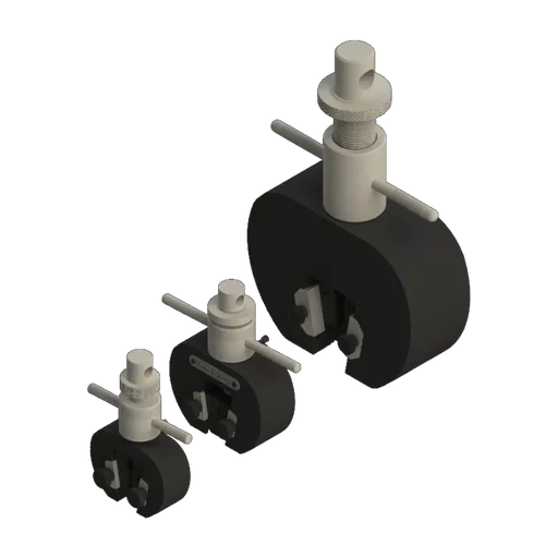
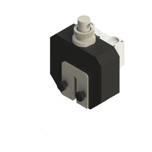
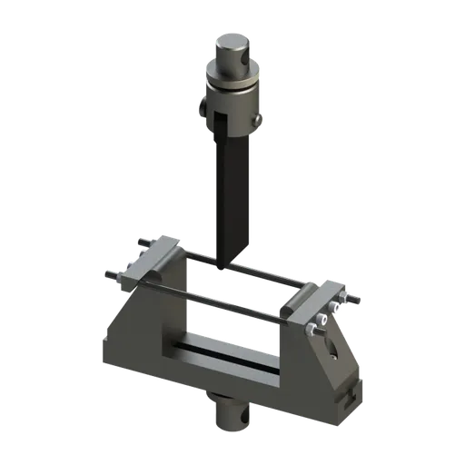
Capacity is chosen from the expected breaking force, with a margin: thin plate strips and fasteners fit machines from 5 to 50 kN (MBIOII-50-M2); test specimens from 10 to 20 mm plate, like the one in example 1, and rebar call for 100 to 200 kN (MBIOII-200-M2); thick plate and larger bars, the machines from 300 kN to 1,000 kN (MBIOII-300-M2 and up). The BioLab software records the curve and issues the report for each test specimen, which goes into the qualification record. To size the machine for your test specimens, request a quote.
Standards cited
The standards below are the ones cited in the text, with the current edition checked on October 1, 2026. The ABNT (Brazilian), ASME, AWS and CNEN (Brazilian nuclear regulator) documents are listed without links.
| Standard | Subject | Edition |
|---|---|---|
| ISO 9712 | qualification and certification of NDT personnel | 2021 (5th edition) |
| ABNT NBR NM-ISO 9712 | same subject, Brazilian adoption (identical to ISO 9712:2021) | 2025 |
| ISO 17635 | NDT of welds: general rules and selection of the method | 2025 (the 2016 edition was withdrawn) |
| ISO 17637 | visual testing of welded joints | 2016 (confirmed in 2022) |
| ISO 3452-1 | penetrant testing, general principles | 2021 |
| ISO 9934-1 | magnetic particle testing, general principles | 2016 (confirmed in 2022) |
| ISO 17636-1 | radiographic testing of welds with film | 2022 |
| ISO 11666 | ultrasonic testing of welds: acceptance levels | 2018 (under revision) |
| ISO 15614-1 | welding procedure qualification for steels and nickel | 2017, with 2019 amendment (under revision) |
| ISO 5173 | bend tests on welds | 2023 |
| ISO 6506-1 | Brinell hardness, test method | 2014 (under revision) |
| ASTM E10 | Brinell hardness of metallic materials | E10-23 |
| ASME BPVC Section V | nondestructive examination of pressure vessels and boilers | 2025 |
| AWS D1.1/D1.1M | structural welding code, steel | 2025 |
| ISO/IEC 17025 | competence of testing and calibration laboratories | 2017 (confirmed in 2023) |
| CNEN NN 6.04 | radiation safety and protection in industrial radiography (Brazil) | 2013 (Resolution 145) |
Other tests and technical references
Tests performed on the Biopdi universal testing machine



















Related technical references
Materials testing: what it is, types, destructive and non-destructive testing, standards and how to choose
Materials testing is the standardized procedure that measures the mechanical, physical, chemical or microstructural properties of a representative sample, or that inspects a part without damaging it. See the five families of tests, the difference between destructive and non-destructive testing, the test specimen, accreditation, the standards and how to choose the right test.
Mechanical testing: what it is, types, what each test measures and standards
Mechanical tests apply a controlled load to a test specimen and measure the material's response. See the types (destructive, non-destructive, static and dynamic), what each test measures, the standards and the machine for each one.
Bend test: what it is, types, rebar, welds and standards (ISO 7438)
The bend test bends a specimen around a mandrel to 90° or 180° and checks for cracks. See test types, NBR 7480 mandrels, weld bend testing and standards.
Frequently asked questions
What are destructive tests?
They are tests that take a test specimen to fracture, permanent deformation or an indentation in order to measure properties such as strength, elongation, toughness and hardness. The sample cannot be put back into service, so the result applies to the lot through sampling. Examples: tensile, compression, flexural, bend, Charpy, fatigue and creep tests.
What are the types of materials testing?
Materials tests fall into five families: mechanical (tensile, compression, flexural, hardness, impact, fatigue), nondestructive (visual, penetrant, magnetic particle, ultrasonic, radiographic), metallographic (macrography and micrography), chemical (composition) and physical or thermal (density, conductivity, thermal expansion). In terms of what happens to the part, they all fall into two groups: destructive and nondestructive.
What is the difference between destructive and nondestructive testing?
Destructive testing measures material properties and renders the sample unusable. Nondestructive testing looks for discontinuities, such as cracks, porosity and lack of fusion, without impairing the use of the part, and can be applied to 100% of production. One does not replace the other: ISO 15614-1:2017 requires both to qualify a welding procedure.
What are three types of nondestructive testing?
The three most common in industry are ultrasonic testing, for internal defects, penetrant testing, for surface-breaking defects, and magnetic particle testing, for surface and near-surface defects in ferromagnetic steel. Visual testing comes before all of them, and radiography completes the basic group.
What are the nondestructive testing methods?
ISO 9712:2021 recognizes ten methods: visual, penetrant, magnetic testing (magnetic particle), ultrasonic, radiographic, eddy current, acoustic emission, thermographic, leak testing and strain gauge testing. ABENDI (the Brazilian Association of Nondestructive Testing and Inspection) also certifies techniques such as phased array and ACFM.
What makes a test nondestructive?
A test is nondestructive when the part comes out of it fit for use, with no change in the properties or dimensions that matter for its function. NDT finds and sizes discontinuities, such as cracks and pores, through a physical phenomenon (light, capillarity, magnetic field, ultrasound, radiation), and the result is an indication compared against an acceptance criterion.
What are examples of nondestructive testing?
Ultrasonic testing of a weld bead, penetrant testing of a casting, magnetic particle testing of a steel shaft, gamma radiography of piping, eddy current testing of heat exchanger tubes and thermography of an electrical panel. In every case, the part remains fit for use after the inspection.
What is the standard for nondestructive testing?
There is no single standard. Personnel are certified under ISO 9712:2021, published in Brazil as ABNT NBR NM-ISO 9712:2025 and applied by ABENDI's SNQC (the Brazilian national qualification and certification system). Each method has its own standard, such as ISO 3452-1 for penetrant testing and ISO 17636-1 for weld radiography. For welds, ISO 17635:2025 guides the choice of method; for pressure vessels, Section V of the ASME code applies.
Is hardness testing destructive or nondestructive?
It is destructive in the strict sense, because it leaves a permanent indentation, and on a cut specimen it makes the sample unusable. On a large, thick part it works as a practically nondestructive check, provided the thickness is at least 8 times the indentation depth (ISO 6506-1) or 10 times (ASTM E10) and the surface is not functional. It is not an NDT method.
When should you use destructive testing and when NDT?
Destructive testing is used to qualify materials, welding procedures and welders, to accept lots by sampling, and for development and failure analysis. NDT is used to inspect every part produced, one-off or expensive parts and equipment in service. For critical parts both are used: destructive testing on a witness specimen and 100% NDT on the part.
Can ultrasonic testing replace the tensile test?
No. Ultrasonic testing locates and sizes defects, but it does not measure yield strength, tensile strength or elongation. Those values require a tensile test on a universal testing machine, according to ISO 6892-1 or ASTM E8/E8M.
Who can perform nondestructive testing?
A professional qualified and certified in the appropriate method and level (1, 2 or 3) according to ISO 9712. In Brazil, certification is carried out by ABENDI's SNQC, active since 1991. Industrial radiography in Brazil also requires a licensed facility and personnel registered with CNEN (the National Nuclear Energy Commission), under standard NN 6.04.
Who performs destructive tests and issues the report?
A testing laboratory with a verified machine and personnel trained in the test method standard, either in-house or contracted. When the report must be valid before a customer or regulator, the laboratory must be accredited to ISO/IEC 17025:2017 for that test; in Brazil, accreditation is granted by Cgcre, the accreditation body of Inmetro.
Are there nondestructive mechanical tests?
Yes, in a narrow sense. A proof load test within the elastic range, hardness testing with a portable hardness tester on a large, thick part and measuring the modulus of elasticity from the vibration frequency all assess mechanical behavior without making the part unusable. None of them, however, measures tensile strength or elongation, which require taking the material to fracture.
Which tests qualify a welding procedure?
Under ISO 15614-1:2017, level 2, a full-penetration butt joint receives visual testing, radiographic or ultrasonic testing and surface crack detection, all at 100%, followed by 2 transverse tensile tests, 4 bend tests, 2 Charpy sets, hardness testing and 1 macro examination. At level 1, visual testing, the 2 tensile tests and the 4 bend tests are enough.
Can magnetic particle testing be used on stainless steel?
Not on austenitic stainless steel, such as the 300 series, which is not ferromagnetic. ISO 9934-1 limits the method to ferromagnetic materials. In these cases, penetrant testing is used, which ISO 15614-1 itself specifies for nonmagnetic materials, or eddy current testing.