
The Brinell hardness test presses a hard metal (tungsten carbide) ball, 1 to 10 mm in diameter, into the metal surface with a fixed force, measures the diameter of the indentation left behind and calculates the HBW hardness as the force divided by the area of the indented spherical cap. The formula is HBW = 0.102 × 2F / [πD(D − √(D² − d²))], with F in newtons and D and d in millimeters, and the result is written with the full scale, as in 229 HBW 10/3000: hardness 229, 10 mm ball and a force of 3,000 kgf (29.42 kN). The method is defined by ISO 6506-1:2014, adopted in Brazil as ABNT NBR ISO 6506-1:2019, and by ASTM E10-23. The Brinell hardness number is also written as BHN (Brinell hardness number), and the instrument that performs the test is the Brinell hardness tester.
This article covers the method in depth: where the formula comes from, how to choose the ball and the force, the valid range of the indentation diameter, the minimum thickness under ISO and ASTM, the measurement, the report and three worked examples. The comparison of all hardness methods, with a short step-by-step for each, is in the article on hardness testing; the concept and the HRC, HV and HB conversion table are in hardness of materials.
One point runs through the whole text and gets its own section at the end: the Brinell test measures a single variable, the resistance of the surface to localized indentation. Yield strength, elongation, necking, modulus of elasticity and toughness do not come from the HBW number; they come from tests performed on a universal testing machine and from the impact test.
How the Brinell test works
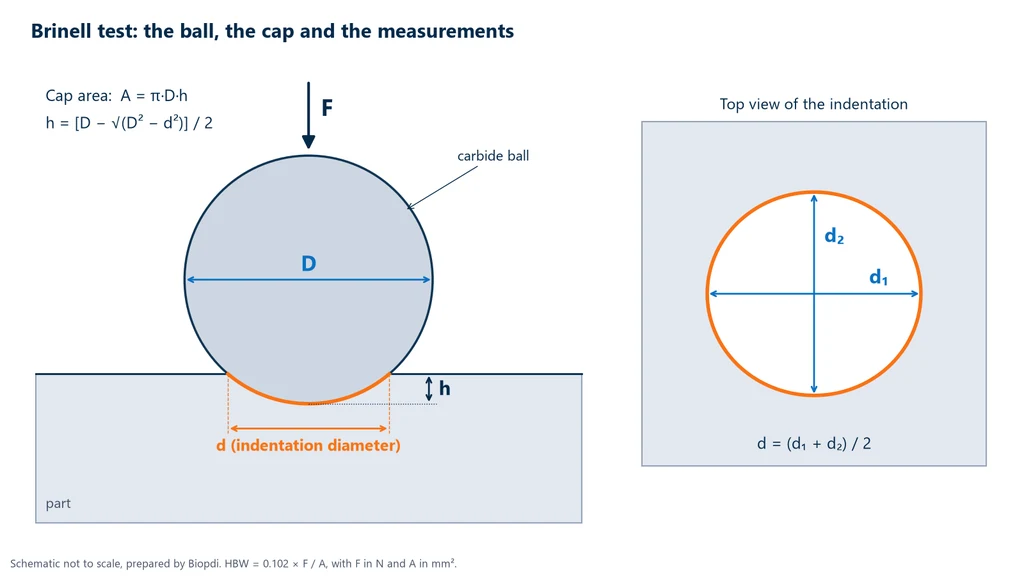
Brinell hardness is a metal's resistance to permanent deformation under a ball, expressed as the test force divided by the area of the cap the ball leaves behind. In the test, the ball, of diameter D, is pressed against the part with force F, without shock and perpendicular to the surface. The force is held for a few seconds and then removed. The part is left with an indentation in the shape of a spherical cap, whose diameter d is measured under a microscope in two perpendicular directions. A soft material leaves a wide indentation; a hard material, a narrow one. The hardness is the ratio between the force and the curved area of this cap, which the standard assumes has the shape of the unloaded ball.
The diagram below shows, not to scale, the four quantities of the test: the ball of diameter D, the force F, the cap of depth h and the diameter d, which in the top view is the average of the two measured diameters, d1 and d2.
The indenter today is always a hard metal ball, that is, sintered tungsten carbide. The W in the HBW symbol comes from Wolfram, the German name for tungsten. Older editions of ISO 6506 allowed a hardened steel ball, and hardness was written HB or HBS; the steel ball deformed when testing hard material and distorted the measurement. ISO 6506-1:2014 only allows hard metal, and all ASTM E10-23 scales are HBW. Anyone still describing the test with a "hardened steel ball" is citing a standard that is no longer valid.
The method was presented by the Swedish engineer Johan August Brinell at the 1900 Paris Exposition, and the full report was published in 1901 in the Journal of the Iron and Steel Institute. It was the first standardized indentation hardness test and is still the one with the largest indentation among bench methods, which defines both its advantages and its limitations.
The Brinell hardness formula: derivation and variables
The Brinell hardness formula divides the test force by the curved area of the indented spherical cap, calculated from the ball diameter D and the indentation diameter d. It follows from the cap geometry in four steps, and knowing them avoids the most common calculation errors.
- Cap area. A cap of height h, cut from a sphere of diameter D, has a lateral area A = π·D·h.
- Depth as a function of d. From the triangle formed by the ball radius, the indentation radius and the distance from the center to the surface, h = [D − √(D² − d²)] / 2.
- Area as a function of d. Substituting, A = (π·D/2)·[D − √(D² − d²)]. We measure d, which is easy to read, instead of h, which cannot be read accurately.
- Hardness. In the original definition, with F in kilogram-force, HB = F/A = 2F / {π·D·[D − √(D² − d²)]}. In the International System, with F in newtons, it is multiplied by 0.102, which is 1/9.80665, the conversion factor from newton to kilogram-force.
This gives HBW = 0.102 × 2F / {π·D·[D − √(D² − d²)]}. The 0.102 factor exists only to preserve the historical numbers: a steel that gave 229 kgf/mm² in 1920 still gives 229 HBW today. That is why the result is written without a unit, with only the symbol and the scale. The table summarizes the variables:
| Symbol | Meaning | Unit | Values and rule |
|---|---|---|---|
| D | Ball diameter | mm | 10, 5, 2.5 or 1 |
| F | Test force | N | from 9.807 N to 29.42 kN |
| d1, d2 | Diameters measured at about 90° | mm | d is the average of the two |
| d | Mean indentation diameter | mm | from 0.24D to 0.6D |
| h | Indentation depth | mm | [D − √(D² − d²)] / 2 |
| 0.102·F/D² | Force-diameter ratio | dimensionless in practice | 1, 2.5, 5, 10, 15 or 30 |
One consequence of the derivation is useful before the test. Since A = π·D·h and HBW = 0.102·F/A, the expected depth is h = 0.102·F / (π·D·HBW), or h = F/(π·D·HBW) with F in kgf. With the approximate hardness of the material, you can predict the depth and check the minimum thickness of the part without making a single indentation, as in example 2 below.
The calculation can be done with the formula or with the ISO 6506-4 table, which gives HBW as a function of d for each ball and force combination. The result is rounded to three significant figures: 217, not 217.3.
Ball, force and force-diameter ratio
The force-diameter ratio 0.102·F/D² is the ratio between the force, in kgf, and the square of the ball diameter, and it is what defines the Brinell test scale; choosing the scale is the main decision of the test. The reason is geometric similarity. For the same hardness, the cap area is proportional to F; if F grows with D², the area grows with D², and the indentation of a 5 mm ball is a scaled-down copy of the indentation of a 10 mm ball, with the same d/D ratio. Tests with the same ratio therefore give comparable values, even with different balls. Tests with different ratios are not comparable.
The ratio depends on the material and the expected hardness. ISO 6506-1 recommends 30 for steel and nickel and titanium alloys; 10 or 30 for cast iron, depending on whether it is below or above 140 HBW; 5, 10 or 30 for copper and its alloys; 2.5 to 15 for light metals; and 1 for lead and tin. The complete table by material and hardness range is in the article on hardness testing. Within the chosen ratio, the standard calls for the largest ball the part allows, because it tests the largest area and gives the most representative result.
Each ratio corresponds to a set of scales. The table shows the most common ones, with the force in newtons and the hardness range each covers with d between 0.24D and 0.6D (values from ISO 6506-1 and ASTM E10-23, summarized):
| Scale | Force (N) | Ratio 0.102·F/D² | HBW range |
|---|---|---|---|
| HBW 10/3000 | 29,420 | 30 | 95.5 to 650 |
| HBW 10/1500 | 14,710 | 15 | 47.7 to 327 |
| HBW 10/1000 | 9,807 | 10 | 31.8 to 218 |
| HBW 10/500 | 4,903 | 5 | 15.9 to 109 |
| HBW 10/250 | 2,452 | 2.5 | 7.96 to 54.5 |
| HBW 10/100 | 980.7 | 1 | 3.18 to 21.8 |
| HBW 5/750 | 7,355 | 30 | 95.5 to 650 |
| HBW 2.5/187.5 | 1,839 | 30 | 95.5 to 650 |
| HBW 1/30 | 294.2 | 30 | 95.5 to 650 |
The last four rows show geometric similarity in practice: with a ratio of 30, the 10, 5, 2.5 and 1 mm balls cover the same hardness range. ASTM E10-23 also adds the 1.25 ratio (for example, HBW 10/125, with 1,226 N). The ceiling of about 650 HBW is the limit of the method: above it the hard metal ball itself starts to deform, and the way forward is the Vickers or the Rockwell test.
The valid diameter range: from 0.24D to 0.6D
The standard requires the mean diameter to fall between 0.24D and 0.6D, that is, between 2.4 and 6.0 mm with the 10 mm ball. The two limits have different physical reasons. At the low end, the indentation is small and shallow: the same absolute reading error weighs more on the result, and the edge of the cap is more affected by the surface finish. At the high end, the ball sinks too deep, the surrounding deformation spreads, the edge of the indentation loses sharpness and the result starts to depend on the chosen force, breaking geometric similarity.
The chart below shows both effects for the HBW 10/3000 scale. On the left, hardness as a function of d: the curve is steep for small indentations and flat for large ones, and the point from example 1 (d = 4.10 mm, 217 HBW) sits in the middle of the range. On the right, the relative error in HBW caused by a 0.01 mm error in reading d: 0.85% at the lower limit, 0.51% at 4.10 mm and 0.38% at the upper limit, growing quickly below 2.4 mm.
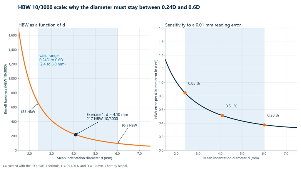
The limits of the range match the scale table. With d = 6.0 mm, √(100 − 36) = 8.0, the area is π × 10 × 2.0 / 2 = 31.42 mm² and the hardness is 3,000 / 31.42 = 95.5 HBW. With d = 2.4 mm, the result is 653 HBW, which ASTM rounds to 650. A d outside the range does not by itself invalidate the test, but the d/D ratio must be stated in the report; in practice, the solution is to change the force.
Why Brinell is the test for castings and forgings
The Brinell indentation is large: with the 10 mm ball, the diameter is between 2.4 and 6 mm, an area hundreds of times larger than that of a routine Vickers indentation. This area covers many grains, phases and particles at once, and the resulting number is an average of the microstructure. In cast iron, for example, the metallic matrix coexists with graphite flakes or nodules that are much softer; a small indentation may land entirely on the matrix or on the graphite and give very different numbers from one point to another, while the large ball averages the two.
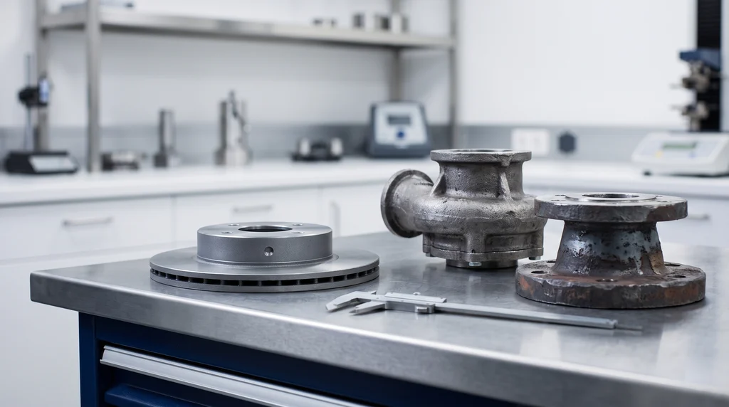
The photo shows cast iron and forged steel parts, the typical field of the Brinell test: the large ball indentation averages a coarse, heterogeneous microstructure that a small indentation would read point by point.
The same feature explains why Brinell tolerates surfaces that are only machined: a roughness of a few micrometers is small compared with a cap several millimeters wide. That is why the method is used for incoming inspection of castings (brake discs, blocks and housings), forgings, large-section bars and tubes, and for heat treatment control of parts in the annealed, normalized or quenched and tempered condition. ASTM E10-23 states that the test is accepted for inspection of commercial shipments.
The limitation is the size of the mark. A cap 4 to 5 mm in diameter and almost half a millimeter deep cannot be left on a functional surface, and the test requires a thickness that thin sheets and hardened layers do not have. That is why hardened steel, thin sheet and carburized layers go to other methods.
Advantages and limitations of the Brinell test
The advantages and limitations of the Brinell test come from the same cause, the size of the indentation. The table summarizes both columns, with the number that sets the limit in each case:
| Advantage | Limitation |
|---|---|
| Indentation of 2.4 to 6 mm (10 mm ball) averages a coarse or heterogeneous microstructure | The mark ruins functional surfaces and small parts |
| Tolerates surfaces that are only machined or ground | Requires a thickness of 8h (ISO) or 10h (ASTM), which rules out thin sheet and carburized layers |
| Covers about 3 to 650 HBW by changing ball and force | Above about 650 HBW the hard metal ball is no longer suitable |
| Accepted for inspection of commercial shipments (ASTM E10-23) | Optical reading, slower than the direct reading of Rockwell |
Step-by-step test procedure per ISO 6506-1 and ASTM E10
The Brinell test has nine steps: prepare the surface, check the thickness, control the temperature, verify the machine, apply the force, hold it, position the indentations, measure and calculate. The sequence below follows ISO 6506-1:2014, which is identical to ABNT NBR ISO 6506-1:2019 (its Brazilian adoption). Where ASTM E10-23 differs, the difference is noted. The numbers come from the standards, summarized in our own words.
- Prepare the surface. It must be smooth and flat, with no scale, dirt or lubricant. With a 10 mm ball, machining or grinding is enough. With 2.5 mm and 1 mm balls, polishing may be needed, for example on the metallographic grinding and polishing machine. Preparation must not heat or work harden the surface, because either one changes the hardness.
- Check the thickness. Under ISO, the part must be at least 8 times the indentation depth h. Under ASTM, it must be at least 10 times. A visible mark on the back means the part is too thin. This difference between the two standards fails more parts than any other, so it is explained in detail below.
- Control the temperature. The test is run between 10 °C and 35 °C. When the temperature must be controlled, use 23 ± 5 °C.
- Verify the machine. Do this on the day of use, on a certified reference block, in the scale you will use. Direct and indirect verification of the machine follow ISO 6506-2, and the blocks follow ISO 6506-3. For indirect verification, ASTM E10-23 also sets repeatability and error limits, and these get tighter as the reference block gets harder.
- Apply the force. Apply it perpendicular to the surface, without shock or vibration, and reach the full value in 2 to 8 s (7 s nominal).
- Hold the force for 10 to 15 s (14 s nominal). Materials that keep flowing under load need a longer time, with a tolerance of ±2 s, and that time goes in the designation.
- Position the indentations. Each center must be at least 2.5d from the edge and at least 3d from the center of the next indentation. Near an edge there is not enough material to contain the deformation. Near another indentation, the ball lands in the region the first one work hardened.
- Measure two diameters at roughly right angles, under the same lighting used to verify the machine, and use their mean. On a ground surface, measure at about 45° to the grinding marks. On a curved surface the indentation comes out slightly elliptical, so use the mean of the two axes. The standard sets a minimum radius of curvature relative to the ball diameter. Automatic systems may take more measurements or use the projected area.
- Calculate and round to three significant figures, and report the result with the full scale designation.
Minimum thickness: 8h under ISO, 10h under ASTM
Every indentation plastically deforms a region much larger than the spherical cap itself. If the part is thin, this region reaches the support. The anvil then carries part of the load, the diameter comes out smaller than it should, and the hardness reads high. ISO 6506-1 sets the minimum at 8 times the depth, and ASTM E10-23 sets it at 10 times. The table compares the two for a 10 mm ball, with h calculated from the depth formula:
| d (mm) | h (mm) | ISO, 8h (mm) | ASTM, 10h (mm) |
|---|---|---|---|
| 2.4 | 0.146 | 1.17 | 1.5 |
| 3.0 | 0.230 | 1.84 | 2.3 |
| 4.0 | 0.417 | 3.34 | 4.2 |
| 5.0 | 0.670 | 5.36 | 6.7 |
| 5.8 | 0.927 | 7.42 | 9.3 |
The ASTM column matches the thickness table in E10-23. The ISO column was calculated as 8h; the official table is in Annex B of ISO 6506-1. A 4 mm thick part with a 4.0 mm indentation passes under ISO and fails under ASTM. That is why the report must always state which standard was followed.
Measuring the diameter and reporting the result
Measurement is the largest source of error in the Brinell test, because everything depends on d. ASTM E10-23 sorts measuring systems into two types. Type A (a microscope with movable lines, a computerized system or image analysis) must resolve at least 0.0100 mm with the 10 mm ball. Type B, a 20× or 40× handheld magnifier with a fixed scale, must not be used with the 2.5 mm and 1 mm balls, because their indentations are too small for it.
The designation gives, in this order: the value, the symbol HBW, the ball diameter in mm, the force in kgf and, if it is not 10 to 15 s, the dwell time:
- 229 HBW 10/3000: 10 mm ball, 3,000 kgf (29.42 kN), standard dwell time;
- 350 HBW 5/750: 5 mm ball, 750 kgf (7.355 kN), standard dwell time;
- 600 HBW 1/30/20: 1 mm ball, 30 kgf (294.2 N), force held for 20 s.
Under ASTM E10-23, only the HBW 10/3000 scale with 10 to 15 s may be written as just "HBW", without the suffix. In every other case, and always under ISO, a value without its scale is ambiguous. "220 HB" could have been measured with different force-diameter ratios and cannot be compared with anything.
Test report and portable Brinell testers
The ISO 6506-1 test report includes the standard, the specimen identification, the date, the result with its full designation, the temperature if it was outside 10 °C to 35 °C, the d/D ratio if it was outside 0.24 to 0.60, and the basis for any conversion to another scale. The standard itself states that there is no general method for converting Brinell hardness exactly to other scales or to tensile strength. We cover this later in the article.
ISO 6506-1 applies to both bench and portable machines. ASTM E10-23 accepts a portable tester that uses the Brinell principle and passes direct and indirect verification, but only when a bench machine is impractical, and it must be verified daily on site. Portable testers that pass only indirect verification fall under ASTM E110. Instruments that measure by another principle, such as Leeb rebound, display a converted Brinell value, which is not a Brinell test result.
Worked examples
The three examples use only the formulas and rules covered above: calculating HBW with every check, choosing the scale for a thin sheet and choosing the force for an aluminum alloy.
Example 1: calculating HBW from the indentation. A 6 mm thick steel block is tested with a 10 mm ball and 29,420 N (3,000 kgf). Under the microscope, d1 = 4.12 mm and d2 = 4.08 mm.
- Mean diameter: d = (4.12 + 4.08) / 2 = 4.10 mm. The ratio d/D = 0.41 is between 0.24 and 0.60.
- D² − d² = 100 − 16.81 = 83.19, and √83.19 = 9.1209 mm.
- D − √(D² − d²) = 10 − 9.1209 = 0.8791 mm, so h = 0.4396 mm.
- π·D·(D − √(D² − d²)) = 31.416 × 0.8791 = 27.619 mm².
- HBW = 0.102 × 2 × 29,420 / 27.619 = 6,001.7 / 27.619 = 217.3, or 217 HBW 10/3000. Check in kgf: 2 × 3,000 / 27.619 = 217.2.
- Thickness: 8h = 3.52 mm (ISO) and 10h = 4.40 mm (ASTM). The 6 mm block meets both standards.
- Spacing: the next indentation must be at least 3d = 12.3 mm away, center to center, and its center at least 2.5d = 10.25 mm from the edge.
Example 2: a thin sheet that fails the thickness check. A 3 mm steel sheet with an expected hardness of 200 HBW is to be tested. Can the HBW 10/3000 scale be used?
- Expected depth, with F in kgf: h = 3,000 / (π × 10 × 200) = 0.477 mm.
- Minimum thickness under ISO: 8 × 0.477 = 3.82 mm, which is more than 3 mm. The scale fails.
- Switch to HBW 5/750, which has the same force-diameter ratio of 30 and gives a comparable result: h = 750 / (π × 5 × 200) = 0.239 mm.
- Minimum thickness: 8h = 1.91 mm (ISO) and 10h = 2.39 mm (ASTM). The 3 mm sheet meets both.
- Expected diameter: d = 2√[h(D − h)] = 2√(0.239 × 4.761) = 2.13 mm, with d/D = 0.43, within the range. The center-to-center spacing drops to 3 × 2.13 = 6.4 mm.
Example 3: choosing the force for an aluminum alloy. An aluminum alloy part is expected to be about 60 HBW, and the lab has a 10 mm ball. Which force should be used?
- Light metals between 35 and 80 HBW use a force-diameter ratio of 5, 10 or 15. With a ratio of 10, F = 10 × 10² / 0.102 = 9,804 N, which is the tabulated scale HBW 10/1000 (9,807 N).
- Expected area, in kgf: A = 1,000 / 60 = 16.67 mm². Depth: h = A / (π·D) = 0.531 mm.
- Expected diameter: d = 2√[0.531 × (10 − 0.531)] = 4.48 mm, with d/D = 0.45. Within the range. The minimum thickness under ISO is 8 × 0.531 = 4.24 mm.
- Cross-check with the steel scale, HBW 10/3000: A = 3,000 / 60 = 50 mm², h = 1.59 mm and d = 7.32 mm, with d/D = 0.73. Out of range, and the part would need to be 12.7 mm thick. That is why aluminum is not tested at 3,000 kgf.
What Brinell hardness does not measure: why to complement it with a universal testing machine
The Brinell test measures a single quantity: the resistance the surface offers to localized penetration by a ball, under a very particular stress state concentrated just beneath the indentation. It is a useful, fast and almost non-destructive measurement, but it is only one. ASTM E10-23 notes that hardness at one point may not represent the whole part, and ISO 18265 states that each hardness value applies only to the immediate region of the indentation.
What hardness does not tell you is exactly what determines whether a material is fit for a structure, a shaft or a pressure vessel: where it starts to deform permanently, how much it elongates before fracture, how much it stretches elastically and how much energy it absorbs before it breaks. Each of these properties has its own test. The table shows what hardness tells you, the test that measures each property and the equipment:
| Property | Does hardness tell you? | Test that measures it | Equipment |
|---|---|---|---|
| Ultimate tensile strength (Rm) | Only an estimate, with no acceptance value | Tensile | Universal testing machine with grips |
| Yield strength (ReH, Rp0.2) | No; the correlation is even weaker than for Rm | Tensile with extensometer | Universal testing machine with extensometer |
| Elongation after fracture (A) | No | Tensile to fracture | Universal testing machine |
| Reduction of area (Z) | No | Tensile to fracture | Universal testing machine |
| Modulus of elasticity (E) | No | Tensile with extensometer | Universal testing machine with extensometer |
| Compressive strength | No | Compression | Universal testing machine with platens, or a press |
| Flexural strength | No | 3-point or 4-point bending | Universal testing machine with flexural fixture |
| Ductility in bending (cracks or not) | No | Bend | Universal testing machine with bend fixture |
| Impact toughness (J) | No | Charpy or Izod impact | Impact pendulum |
Almost the entire right-hand column is the same machine. The tensile test delivers, from a single curve, the yield strength, the ultimate tensile strength, the elongation and the reduction of area, which measure ductility, and, with an extensometer, the modulus of elasticity; the stress-strain curve shows all of this at once. The compression test, the flexural test and the bend test use the same machine with other fixtures. Impact toughness is left to the impact test, on a pendulum.
The Rm ≈ 3.45 × HB correlation and its limits
For steels there is a practical correlation between hardness and strength: Rm (MPa) ≈ 3.45 × HB, the Callister and Rethwisch rule, derived from Metals Handbook data. The physical basis comes from Tabor (1956): the mean pressure under the indenter is about three times the material's flow stress at a representative strain. Hardness therefore indirectly measures a flow stress that already includes some work hardening, not Rm itself. It works for steels because in them the relationship between yield, work hardening and Rm is similar from one steel to another.
The limits of the rule are written in the conversion standards themselves. ISO 18265:2013 states that the tensile strength estimate is the least reliable of all hardness conversions, that the converted value applies directly only to the exact material that generated the table, and that it does not replace the result obtained by the standardized method. ASTM E140 states that conversions are approximate and should be used only when it is not possible to test under the specified conditions. In practice, the rule is for screening and process control, never for material acceptance.
Worked example: the hardness estimate versus the tensile test
A cold-drawn AISI 1045 steel bar measured 179 HB. The typical certificate for this material, obtained from a tensile test (MatWeb data for 19 to 32 mm bar), gives Rm = 625 MPa, yield strength of 530 MPa, elongation of 12% and reduction of area of 35%.
- Estimate from hardness: Rm ≈ 3.45 × 179 = 617.6 MPa.
- Error: (617.6 − 625) / 625 = −1.2%. For a steel, the estimate was quite accurate.
- What the tensile test added: the yield strength of 530 MPa, which is 85% of Rm, a typical ratio for drawn material and well above the roughly 55% of the same hot-rolled 1045 (310 of 565 MPa); the elongation of 12%; the reduction of area of 35%; and, with an extensometer, the modulus. None of these numbers comes out of 179 HB. A designer sizing the bar on yield strength, as is usual, would not have the data needed.
- Counter-check on a material of the same hardness: an ASTM A48 Class 30 gray cast iron, with typical hardness of 187 to 241 HB, measures 200 HB. The steel rule gives 3.45 × 200 = 690 MPa. The class minimum is 207 MPa (30 ksi). The estimate is 3.3 times the guaranteed minimum, an error of 233%, and the elongation of gray iron is below 0.5%, against 12% for the steel.
The chart below places these materials on the same plot. The cold-drawn 1045 steel falls on the 3.45 × HB line, and so do the annealed and hot-rolled 1045, both at about 163 HB and 565 MPa. In the same hardness range, ASTM A536 65-45-12 ductile iron (156 to 217 HB, minimum Rm of 448 MPa) sits below the line, and gray iron far below it.
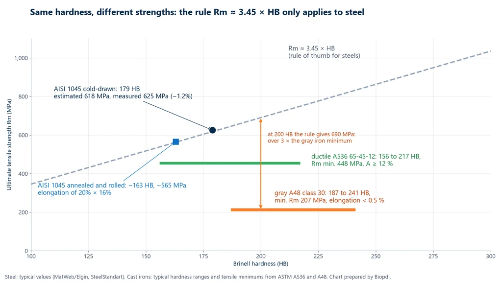
Ductile and gray iron are the most instructive case of "same hardness, different behavior". The metallic matrix of the two can be similar, and so can the hardness; what changes is the shape of the graphite. In gray iron it forms flakes, which act as internal notches and concentrate stress: the material fractures at 207 MPa with practically zero elongation. In ductile iron the graphite forms spheres, which do not concentrate stress: the material reaches 448 MPa with 12% elongation. The Brinell ball, which compresses the surface, does not see this difference; the tensile test, which opens the notches, does. The graphite shape can be seen under a metallurgical microscope.
Even among steels, hardness does not capture the full behavior. Annealed and hot-rolled 1045 both show about 163 HB and almost identical typical tensile properties, but with 20% elongation when annealed and 16% when hot rolled. And a quenched and tempered steel in the temper embrittlement range can have the same hardness as a properly tempered steel and absorb much less energy in impact. Only the impact test reveals this.
How much machine the complementary tensile test requires
For the cold-drawn 1045 example, a machined test specimen of 10 mm diameter has a cross-section of π × 10² / 4 = 78.54 mm². The force at yield is 530 × 78.54 = 41.6 kN, and the maximum force is 625 × 78.54 = 49.1 kN. That is within 2% of the full scale of a 50 kN machine, with no margin: the test calls for a 100 to 200 kN machine. With a 6 mm specimen, which ISO 6892-1 also allows, the cross-section drops to 28.27 mm² and the maximum force to 17.7 kN, within the 50 kN machine. Choosing the geometry is covered in detail in the article on the test specimen and in the guide to ASTM E8 and ISO 6892-1.
Brinell vs. Rockwell, and HB vs. HRC
The difference between the Brinell and Rockwell tests lies in the quantity measured: Brinell measures the diameter of a ball indentation, and Rockwell the depth of the indentation under a preload. Brinell measures the diameter of a large indentation, after the force is removed, with a microscope. Rockwell applies a preload, which sets a reference plane, then an additional force, and reads the permanent depth directly on the instrument, still under the preload. The table summarizes:
| Aspect | Brinell (ISO 6506-1, ASTM E10) | Rockwell (ISO 6508-1, ASTM E18) |
|---|---|---|
| Indenter | Tungsten carbide ball, 1 to 10 mm | Diamond cone or small ball, depending on the scale |
| Quantity measured | Indentation diameter, after unloading | Permanent depth, under preload |
| Indentation | Large: averages the microstructure | Small: reads a single point |
| Reading | Optical, slower | Direct, fast |
| Typical use | Castings, forgings, annealed or normalized steel, non-ferrous metals | Series production, hardened steel |
Because the measured quantities are different, there is no formula between HB and HRC. Conversion is done with empirical tables by material group, ASTM E140 and ISO 18265, and it is approximate. The HRC, HV and HB table for steels and its limits are in hardness of materials; the Rockwell procedure is in the hardness test article.
How to interpret a Brinell test result
A Brinell result can only be interpreted with the full scale, the standard followed and the position of the indentation on the part. The points below are the ones that cause the most doubts in test reports and specifications, even among experienced professionals.
Does a diameter outside 0.24D to 0.6D invalidate the test?
Not automatically. ISO 6506-1 requires the d/D ratio to be recorded in the report when it falls outside the range, and the result is no longer directly comparable with others obtained within it. Unless the specification says otherwise, the correct approach is to repeat the test with a different force or ball, keeping the same force-diameter ratio where possible.
Can I compare 200 HBW 10/3000 with 200 HBW 10/1000?
No. The force-diameter ratios are different (30 and 10), and geometric similarity only holds for the same ratio. On the other hand, 200 HBW 10/3000 and 200 HBW 5/750 are comparable, because both have a ratio of 30. That is why the specification must state the scale, not just the number.
Are HB, HBS and HBW the same thing?
Not under the current standard. HB and HBS were the designations from the time steel balls were used; HBW indicates a tungsten carbide ball, the only one allowed today. Old drawings that call for "HB" are, in practice, met with HBW on the corresponding scale, but the report should state HBW.
Does the measured hardness represent the whole part?
It represents the region of the indentation. In a part with a decarburized layer, with surface work hardening or with a hardness gradient from surface to core, such as a thick hardened bar, Brinell reads the surface. ASTM E10-23 makes this caveat explicitly. To know what happens inside, a hardness profile across a section or a tensile test on a specimen taken from the specified location is used.
Is a Brinell value from a portable rebound hardness tester a Brinell value?
No. The rebound instrument measures a ratio of velocities and converts it to HB using a table. The value is converted, not measured by the Brinell principle, and does not comply with ASTM E10. It must be reported as converted, with the table used.
If the hardness is within range, is the material approved?
Only if the product specification accepts hardness as a criterion. Structural steel, rebar, bolts and pressure vessel plate are approved on tensile properties, and sometimes on bend and impact, as defined in the product standard. Hardness within range indicates that the process probably went well; what confirms the properties is the specified test.
Common mistakes in Brinell testing
The mistakes below appear frequently in test reports, course handouts and search results, and each one changes the result or makes it non-comparable.
- Referring to a hardened steel ball. Since ISO 6506-1:2014 only tungsten carbide is used, and the symbol is HBW.
- Writing the value without the scale. "220 HB" states neither the ball nor the force.
- Comparing values from different force-diameter ratios. Only the same ratio gives comparable numbers.
- Ignoring the range of d. Outside 0.24D to 0.6D, change the force, and record d/D if you keep the test.
- Thin part, or indentation too close to the edge or to another indentation. Respect 8h (ISO) or 10h (ASTM), 3d between centers and 2.5d to the edge.
- Confusing the ISO rule with the ASTM rule for thickness. Always state which standard was followed.
- Measuring on a poorly prepared surface, or one that heated up or work hardened during preparation. On a ground surface, measure at 45° to the grinding marks.
- Using the flat-surface formula on a curved surface without accounting for curvature; the ISO formula applies to flat surfaces, and radii of curvature too small relative to the ball invalidate the result.
- Assuming Brinell only uses 500 to 3,000 kgf, held for 10 to 30 s. The scales range from 1 kgf (9.807 N) to 3,000 kgf, and the normal dwell time is 10 to 15 s; a longer time is only for materials that creep under load, and it goes into the designation.
- Writing HBW with a unit, in MPa or kgf/mm². The number is written without a unit, with the symbol and the scale.
- Testing material above about 650 HBW. The ball is out of range; use Vickers or Rockwell.
- Using Rm ≈ 3.45 × HB outside steel, or using it to accept steel.
- Rounding incorrectly. Three significant figures: 217, not 217.3.
Equipment for the tests that complement hardness
Biopdi does not manufacture hardness testers. We manufacture the machine for the tests that hardness cannot replace: tensile, compression, flexural and bend tests, all on the same universal testing machine, just by changing the fixture. The M2 line has a class 1 load cell according to ISO 7500-1:2023 (ABNT NBR ISO 7500-1:2023 in Brazil) and the BioLab software. BioLab plots the force × displacement curve and, with an extensometer, the stress-strain curve. It also calculates yield strength, Rm, elongation and modulus. The panel below shows the machine, what each part does in these tests, and the fixtures.
The universal testing machine in the tests that complement hardness
The M2 line has single-column models from 200 N to 10 kN and dual-column models from 5 kN to 1,000 kN. Each part of the machine has a role in the tests that hardness cannot replace:

- Moving crosshead applies tension, compression or bending at the speed set by the standard
- Load cell class 1: force at yield and at Rm
- Grips and platens wedge grips for tensile tests, platens for compression tests
- Extensometer for offset yield strength and modulus
- BioLab software yield strength, Rm, elongation and modulus
- Control panel and emergency stop positions the crosshead and stops the test
Fixtures for the complementary tests
The fixtures below are mounted on the same machine, according to the test and the standard:
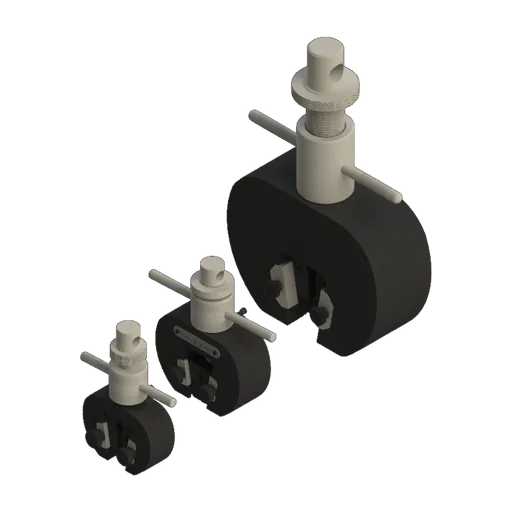
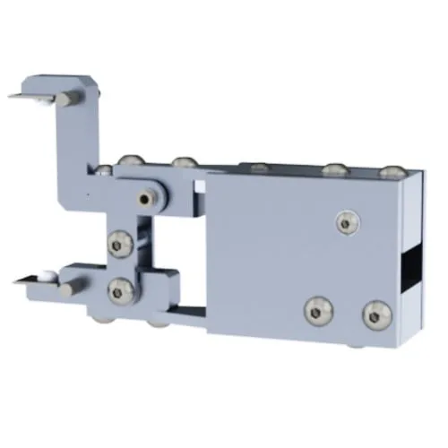
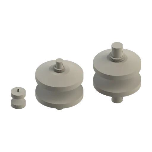
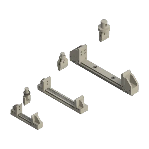
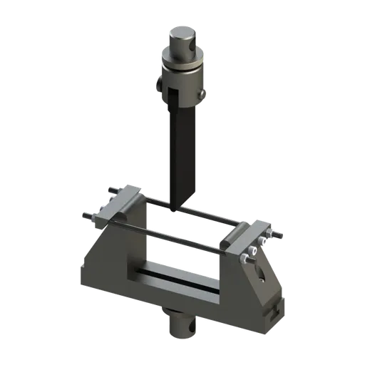
Capacity is chosen from the maximum force of the test specimen. Sheet and machined steel specimens up to about 6 mm in diameter, like the one in the example above, fit the 5 to 50 kN machine (MBIOII-50-M2). 10 mm specimens in medium-carbon steel, and bars and rebar up to 16 mm, need the 100 to 200 kN machine (MBIOII-200-M2). To see the microstructure behind the hardness, such as the graphite shape in a cast iron, the sample is prepared on the grinding and polishing machine and examined under the metallurgical microscope. The other configurations are on the universal testing machine page, and you can request a quote for the materials your lab tests.
Brinell hardness test standards
ISO splits Brinell into four parts: test method, verification of the machine, reference blocks, and table of values. ABNT (the Brazilian standards body) adopts the series as NBR ISO 6506. The table gives the editions and status checked on September 30, 2026, on the official pages (iso.org and store.astm.org) and in the ABNT catalog:
| Standard | Scope | Edition and status |
|---|---|---|
| ISO 6506-1 | Brinell, test method | 2014, confirmed in 2019, under revision at ISO |
| ABNT NBR ISO 6506-1 | Brinell, test method (identical adoption of the ISO standard in Brazil) | 2019, current |
| ISO 6506-2 | verification and calibration of the testing machine | 2017, under revision at ISO |
| ISO 6506-3 | calibration of reference blocks | 2014, confirmed in 2019, under revision at ISO |
| ISO 6506-4 | table of HBW values as a function of d | 2014, confirmed in 2024 |
| ASTM E10 | Brinell hardness of metallic materials, including portable testers | E10-23, active |
| ASTM E110 | Rockwell and Brinell hardness with portable hardness testers | E110-14(2023) |
| ISO 18265 | conversion of hardness values and estimation of Rm | 2013, confirmed in 2024 |
| ASTM E140 | hardness conversion tables | E140-12B(2019)e1 |
ISO is revising ISO 6506-1, and a new edition is in preparation; until it is published, the 2014 edition remains current (status checked on iso.org on October 1, 2026). ABNT NBR ISO 6506-1:2019 canceled and replaced the former NBR NM ISO 6506-1:2010 in Brazil.
Other tests and technical references
Tests performed on the Biopdi universal testing machine



















Related technical references
Hardness test: types, procedure and standards (Brinell, Rockwell, Vickers and Shore)
A hardness test presses a standardized indenter into the part under controlled force and dwell time, then measures the indentation or its depth. See the types, the step-by-step procedure for each method, minimum thickness and spacing, hardness tester verification and standards.
Rockwell hardness test: how it works, HRC and HRB scales and ISO 6508-1
Rockwell hardness test: permanent indentation depth becomes HR = N − h/S. HRC and HRBW scales, ISO 6508-1:2023, and what hardness does not measure.
Peel test: 90°, 180°, T-peel and peel strength calculation
The peel test measures the force per unit width needed to separate bonded materials. See 90°, 180° and T-peel, formula, units and ASTM and ISO standards.
Frequently asked questions
What is Brinell hardness?
Brinell hardness is a metal's resistance to permanent deformation under a hard metal (tungsten carbide) ball. It is calculated as the test force divided by the surface area of the indentation and written as HBW followed by the scale, for example 229 HBW 10/3000. It is defined by ISO 6506-1:2014 and ASTM E10-23.
What is the difference between the Rockwell and Brinell hardness tests?
Brinell presses a hard metal ball of 1 to 10 mm diameter with up to 29.42 kN and measures the indentation diameter with a microscope. Rockwell applies a preliminary force and an additional force with a diamond cone or a small ball, and reads the depth directly on the tester. Brinell averages over a large area and is preferred for castings and forgings; Rockwell is faster and is the standard choice for hardened steel.
How is the Brinell hardness test performed?
The part, clean and flat, rests on a rigid support. The force reaches its full value in 2 to 8 s and is held for 10 to 15 s. After the force is removed, two perpendicular diameters of the indentation are measured and their average is used in the formula, checking that d is between 0.24D and 0.6D (ISO 6506-1).
How do you calculate Brinell hardness?
With the formula HBW = 0.102 × 2F / [πD(D − √(D² − d²))], with F in newtons and D and d in millimeters, rounded to three significant figures. With a 10 mm ball, 29,420 N and d = 4.10 mm, the result is 217 HBW 10/3000.
What is a Brinell hardness tester?
It is the hardness testing machine that applies forces from 9.807 N to 29.42 kN with a hard metal ball and measures the indentation with an optical system. It must be verified according to ISO 6506-2 or the verification annex of ASTM E10, and it comes in bench-top and portable versions.
What is the difference between HRC and HB?
HB, now HBW, comes from the diameter of a ball indentation; HRC comes from the depth of a diamond cone indentation on the Rockwell C scale. There is no formula linking the two: conversion uses empirical tables by material group (ASTM E140 and ISO 18265) and is approximate.
Why is the symbol HBW and not HB?
The W stands for the tungsten carbide ball (Wolfram). Older editions of the standard allowed a steel ball and used HB or HBS. ISO 6506-1:2014 allows only a hard metal ball.
Which force and ball should be used in the Brinell test?
The force-diameter index 0.102·F/D² is chosen by material: 30 for steel and for cast iron of 140 HBW or more, 10 for softer cast iron and for copper from 35 to 200 HBW, 2.5 to 15 for light metals, and 1 for lead and tin. Within that index, use the largest ball the part allows, checking that d is between 0.24D and 0.6D.
What is the minimum part thickness for the Brinell test?
Per ISO 6506-1, at least 8 times the indentation depth; per ASTM E10-23, 10 times. On the HBW 10/3000 scale at 200 HBW, the depth is about 0.48 mm, which calls for 3.8 mm under ISO and 4.8 mm under ASTM.
Can tensile strength be obtained from Brinell hardness?
Only as an estimate, and only for steel: Rm (MPa) ≈ 3.45 × HB. In a cold-drawn 1045 steel, 179 HB gives an estimate of 618 MPa against 625 MPa measured; in a 200 HB gray cast iron, the same rule is off by more than a factor of three. ISO 18265 states that this is the least reliable conversion and that it does not replace the standardized test.
Does Brinell hardness replace the tensile test?
No. Hardness measures only resistance to localized indentation. Yield strength, elongation, necking (reduction of area) and modulus of elasticity come from the tensile test on a universal testing machine, and toughness comes from the impact test.
What is the maximum hardness the Brinell test can measure?
About 650 HBW, at force-diameter index 30 (ASTM E10-23). Above that, the hard metal ball is no longer suitable, and Vickers or Rockwell is used instead.
Who invented the Brinell test?
Swedish engineer Johan August Brinell, who presented the method at the 1900 Paris Exposition. The full report was published in 1901 in the Journal of the Iron and Steel Institute.