
A test specimen (in Brazil often abbreviated CP, from "corpo de prova") is a sample of material with the shape, dimensions and finish defined by the test standard, prepared to measure a property without testing the whole part: a 10 × 20 cm concrete cylinder, a 12.5 mm round steel specimen and a 55 × 10 × 10 mm Charpy bar are all test specimens. Standardization ensures that the stress state in the measured section is known and that the result can be compared between batches and laboratories. Each test has its own specimen: in tensile testing of metals, for example, ISO 6892-1 (ABNT NBR ISO 6892-1:2024 in Brazil) links the length over which elongation is measured to the cross-sectional area, and a round specimen 10 mm in diameter has this length at about 50 mm.
In short:
- There is no single test specimen standard: the shape and dimensions come from the standard for each test and each material.
- Metals (tensile): ABNT NBR ISO 6892-1:2024 and ASTM E8/E8M-25; the ASTM standard round specimen is 12.5 mm in diameter.
- Plastics: ASTM D638-22 (Type I dogbone, 165 mm) and ISO 527-2:2025 (A1, 170 mm) for tensile; ASTM D790-25 (127 × 12.7 × 3.2 mm bar) for flexural.
- Charpy impact: 55 × 10 × 10 mm bar with a 2 mm V-notch (ISO 148-1:2016 and ASTM E23-25).
- Timber, concrete and welds: 5 × 5 × 15 cm prism (NBR 7190-3:2022), 10 × 20 and 15 × 30 cm cylinders (NBR 5738:2015) and specimens transverse to the weld joint (ISO 4136:2022 and ISO 5173:2023).
What a test specimen is and why its shape is standardized
The shape of the test specimen is standardized because it is what makes the stress in the measured section known and the result comparable between laboratories. A real part has holes, corners, thickness variations and regions that work in different ways. If the whole part were placed in the machine, the measured force would tell how much that part can withstand, but not how much the material can withstand, because the stress at each point would be unknown. The test specimen solves this: it is a piece of the material with a geometry so simple that the stress in the section of interest can be calculated as force divided by area. ISO standards call it a test piece; ASTM standards, a specimen. The abbreviation CP is common in Brazilian laboratories, and older Brazilian standards spell the Portuguese term with a hyphen (corpo-de-prova). The term also applies outside mechanical testing: in corrosion, the test specimen is a metal coupon exposed to the environment to measure mass loss over time.
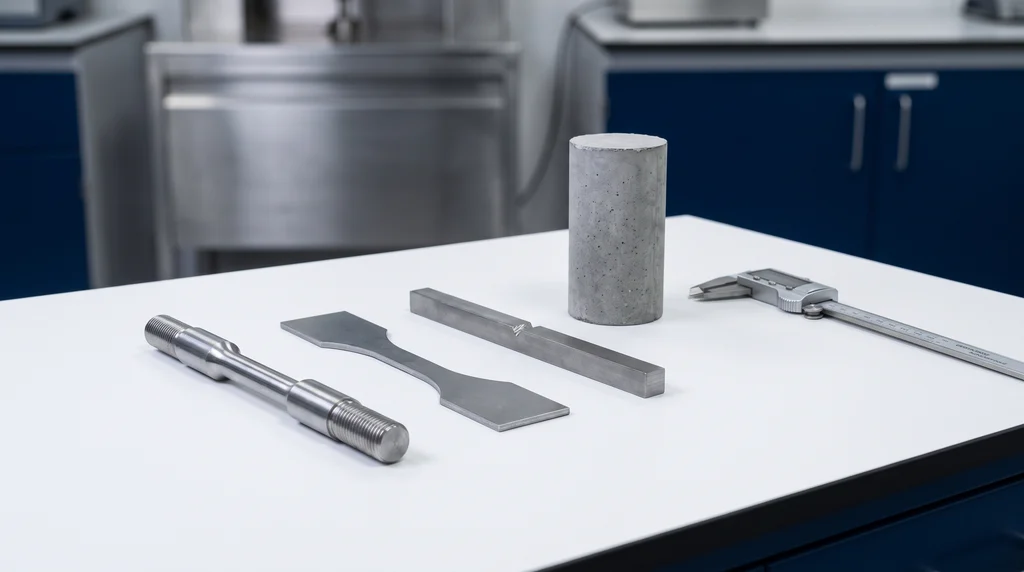
The photo shows test specimens from four tests: the round one, with threaded ends and a reduced section in the middle, and the flat one, cut from sheet, are tensile specimens; the bar with a V-notch is an impact specimen; the cylinder is a concrete specimen for compression. In all of them, the shape concentrates stress in the region the standard is meant to measure.
Three physical reasons explain why the standard fixes the shape instead of letting each laboratory choose:
- The stress state must be known. In a tensile specimen, the middle section is narrower than the ends. Deformation concentrates there, away from the grips, where the stress is uniaxial (along the axis only) and uniform across the section. Near the grip, clamping and friction create stresses in other directions. This is Saint-Venant's principle: the disturbance caused by the way the force is applied dissipates over a distance on the order of the part's width. That is why measurement is done in the middle and not near the ends. The same reasoning applies to the concrete cylinder: friction with the platens confines the ends, and a height of twice the diameter leaves the middle free of this effect.
- Size changes the result in brittle materials. Concrete, ceramics and wood fail from the worst defect contained in the loaded volume. The larger the specimen, the greater the chance it contains a critical defect, and the lower the measured strength tends to be. The classic statistical model of this size effect is Weibull's (1951). It is one of the reasons the standard fixes the dimension and why results from specimens of different sizes should not be mixed without justification.
- Without a standard there is no comparison. Elongation depends on the length over which it is measured; impact energy depends on the notch shape; the strength of a plastic depends on the thickness and the molding orientation. Two laboratories can only compare numbers if they used the same test specimen, and a certificate only proves that the material meets a specification if the test followed the standard it cites.
The test specimen is the starting point of any of the mechanical tests and, more broadly, of materials testing: the same machine gives different results for the same material if the specimen changes.
Sample, test specimen, test set and core: the vocabulary
Sample, test specimen, test set (exemplar) and core are not synonyms: the sample represents the lot, the test specimen is the piece with the geometry of the standard, the test set groups concrete specimens from the same batch and the core is the cylinder drilled from a finished structure. The distinction matters when reading a sampling plan or a test report.
- Sample is the portion taken from a lot or a product to represent it: a piece of bar, an offcut of sheet, an injection-molded plaque, a volume of fresh concrete. One or more test specimens are taken from the sample.
- Test specimen is the piece already with the geometry of the standard, ready for testing. It is not always machined: rebar, wire and cable are tested on the full product cross-section, as shown in the article on steel reinforcing bars.
- Test set (exemplar), in concrete quality control, is the group of test specimens cast from the same batch and tested at the same age; the result of the test set is the highest value among them, according to NBR 12655 (the Brazilian standard for concrete preparation, control and acceptance).
- Core, in concrete, is the cylinder drilled with a rotary core drill from a finished structure, according to ABNT NBR 7680-1:2015 (the Brazilian standard for core extraction), when one wants to know the strength of the concrete in place. In timber testing, the same Portuguese word (testemunho) has another meaning: the first specimen tested to estimate the strength of the sample and set the loads for the others, according to the description of NBR 7190-3:2022 given by Wang Wei (2025).
Within the test specimen itself there is another vocabulary, which comes from tensile testing and recurs in several tests:
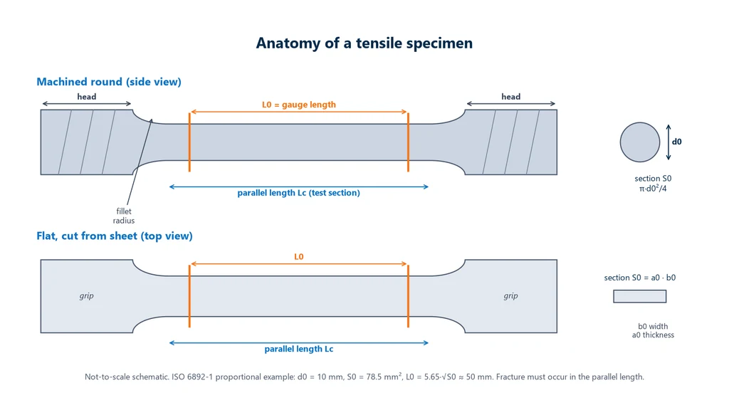
- Grip ends (heads): the ends held in the grips. They can be plain, threaded or shouldered.
- Transition radius (fillet): the curved transition between the grip end and the reduced section. A sharp corner would concentrate stress and make the fracture start there.
- Parallel length (Lc): the section of constant cross-section, also called the reduced section, where deformation should take place and fracture should occur.
- Original gauge length (L0): the distance between two marks, or between the knife edges of the extensometer, within the parallel length. It is the base on which elongation is calculated. ASTM calls it the gauge length and uses the letter G.
- Original cross-sectional area (S0): the cross-sectional area of the parallel length before the test. For a round specimen, S0 = π·d0²/4; for a flat one, S0 = a0·b0 (thickness times width). Stress is the force divided by S0.
The diagram below shows these parts in the two most common formats. At the top, the machined round specimen with threaded ends; at the bottom, the flat specimen cut from sheet, whose wide ends are held by wedge grips. The orange marks delimit L0, always shorter than the parallel length, so that the marks stay away from the transition radius. On the right, the two cross-sections.
One last distinction: a test specimen is proportional when L0 grows with the cross-section, according to the formula L0 = k·√S0, and non-proportional when L0 is fixed, such as 50 mm or 80 mm. ISO 6892-1 prefers the proportional specimen, with k = 5.65. For a round specimen, 5.65·√(π·d0²/4) gives 5.01·d0, that is, about five diameters. Proportionality makes the elongation of a 10 mm and a 20 mm round specimen of the same steel give the same number; the physical reason is in the section on fracture.
Tensile test specimens for metals: ISO 6892-1 and ASTM E8
The tensile test specimen for metals is a machined round bar or a strip cut from sheet, with wider ends and a reduced parallel length where fracture should occur. The two families of standards are ISO 6892-1:2019, adopted in Brazil as ABNT NBR ISO 6892-1:2024, and ASTM E8/E8M-25. Both accept round specimens, machined from bars, and flat specimens, cut from sheet, and both require fracture to occur within the parallel length. What changes is the gauge length:
- Round: ISO uses the proportional specimen, L0 = 5.65·√S0. The ASTM standard round specimen is 12.5 mm in diameter, with L0 of 50 mm (4D) in E8, in inch-pound units, and 62.5 mm (5D) in E8M, in SI units.
- Sheet: E8 has the sheet-type specimen, 12.5 mm wide with a 50 mm gauge length, and the plate-type, 40 mm wide with a 200 mm gauge length, for thick plates. ISO covers thin sheet, from 0.1 to 3 mm, in a dedicated annex; type 2 in that annex is 20 mm wide with an 80 mm gauge length.
Since the same diameter gives different gauge lengths, the elongation on an E8 certificate cannot be compared directly with that of an ISO specification. The details of both standards (speeds, extensometer, rounding and elongation conversion) are in the guide ASTM E8 vs ISO 6892-1, and the test itself, with the curve and the step-by-step procedure, in the article on the tensile test.
Test specimens for plastics and composites
For plastics, the test specimen is usually injection-molded or machined from sheet, and its manufacturing history weighs on the result: the orientation of the chains in the mold flow, residual stresses and absorbed moisture change the strength. That is why plastics standards fix the shape and also the conditioning before the test, typically at 23 °C and 50% relative humidity. 3D-printed test specimens, common in research, inherit the orientation of the layers: the result applies to that print direction and cannot be compared directly with that of an injection-molded specimen.
Tensile: ASTM D638 and ISO 527-2
ASTM D638-22 uses dogbone-shaped test specimens, Type I to Type V. Type I, preferred for rigid and semi-rigid plastics, has an overall length of 165 mm, a narrow section 13 mm wide and 3.2 mm thick, and a gauge length of 50 mm. ISO 527-2:2025 uses the A1, an injection-molded multipurpose specimen, called 1A up to the 2012 edition: 170 mm long, 80 mm parallel length, 10 × 4 mm cross-section and L0 of 75 mm. The two are not interchangeable: different cross-section, length and gauge length give different numbers. Types, speeds and calculations are in the ASTM D638 guide.
Flexural: ASTM D790
In three-point bending, the test specimen is a straight bar, supported on two rollers and loaded at the center. ASTM D790-25 prefers the 127 × 12.7 × 3.2 mm bar, with a span of 16 times the thickness: 16 × 3.2 = 51.2 mm. The span-to-thickness ratio is not a detail: with too short a span, shear force becomes significant and the bar no longer fails by bending at the outer fiber. The setup and calculations are in the ASTM D790 guide, and the test in general in the article on the flexural test.
Polymer matrix composites
For continuous-fiber composites, tensile testing generally follows ASTM D3039/D3039M-17(2025), with a rectangular strip specimen of constant cross-section, without the dogbone shape used for plastics. Machining a reduced section would cut continuous fibers at the transition, and fracture would start right there; the ends usually receive bonded end tabs to protect the strip from the grip pressure. Flexural testing of composites follows ASTM D7264/D7264M-26. The dimensions in each depend on the laminate type and must be read in the standard.
Charpy impact test specimen
The Charpy test specimen is a 55 × 10 × 10 mm bar with a V-notch in the middle, supported at both ends and broken by a pendulum blow to measure the absorbed energy. The standard specimen of ISO 148-1:2016 (ABNT NBR ISO 148-1:2021 in Brazil) and ASTM E23-25 has a notch 2 mm deep, with a 45° angle and a 0.25 mm root radius. Below the notch, 8 mm of ligament remain, the section that actually fractures.
The notch is the reason this test specimen exists. It concentrates stress at a known point and creates a triaxial stress state at the root, which restrains plastic deformation and makes the test severe enough to reveal whether the material behaves in a ductile or brittle manner at that temperature. Since the energy depends heavily on this geometry, the notch is machined with a dedicated tool and checked on a profile projector, and subsize specimens (7.5, 5 or 2.5 mm thick) can only be compared with each other. The complete test is in the article on the impact test.
Hardness: minimum thickness instead of shape
The hardness test does not require a fixed geometry: any part with a flat, smooth face that is firmly supported will do. The requirement is thickness. Every indentation plastically deforms a region larger than the mark; if the part is thin, this region reaches the back face, the anvil starts supporting the indentation and the reading comes out high. The standards set the minimum thickness as a function of indentation size:
- Brinell (ISO 6506-1:2014): at least 8 times the indentation depth.
- Vickers (ISO 6507-1:2023): at least 1.5 times the mean diagonal.
- Rockwell (ISO 6508-1:2023): at least 10 times the residual depth with a diamond indenter and 15 times with a ball.
A visible mark on the back face shows that the limit was violated. Spacing between indentations and to the edge, and the choice of method for thin sheet, are in the article on the hardness test.
Wood test specimen
A wood test specimen is a defect-free prism, cut with the grain in a defined direction relative to the force. Wood is anisotropic: it is much stronger parallel to the grain than perpendicular to it, and its properties change with moisture content. For this reason a wood test specimen is defined by its grain orientation, and the result is referred to a standard moisture content. For species from native forests, ABNT NBR 7190-3:2022 (the Brazilian standard for test methods on timber) describes the test methods on defect-free specimens. These specimens have no knots, cracks or grain deviation, so they measure the material and not the structural member.
For compression parallel to the grain, the specimen is a square-section prism, 5 × 5 cm and 15 cm long, with the grain in the direction of the force. Results are corrected to the reference moisture content of 12%. NBR 7190-1:2022 groups native timbers into strength classes from D20 to D60, where the number is the characteristic compressive strength parallel to the grain, in MPa. The height of three times the side has the same purpose as in the concrete cylinder: it keeps the middle of the prism away from the confinement of the platens. For the same reason, the strain used for the modulus of elasticity is measured in the central portion. Wang Wei (2025, master's dissertation at USP, the University of São Paulo) showed that instruments attached near the ends of this prism tend to overestimate the modulus.
Concrete and mortar test specimens
For concrete, the most common test specimen is the cylinder molded according to ABNT NBR 5738:2015 (the Brazilian standard for molding and curing concrete specimens), 10 × 20 cm or 15 × 30 cm (diameter × height). It is tested in compression according to ABNT NBR 5739:2018 (the Brazilian standard for compression testing of concrete cylinders) to compare the strength obtained with the design fck. The area of the 10 × 20 cylinder is π·100²/4 = 7,854 mm²; the area of the 15 × 30 cylinder is 17,671 mm². The height-to-diameter ratio must be between 1.94 and 2.06 for no correction to be needed, and the ends are ground or capped so that they are flat. The cylinder stays in the mold for at least 24 h and then goes into moist curing at (23 ± 2) °C until the test age, usually 7 and 28 days. The number of specimens is not counted per cubic meter: ABNT NBR 12655:2022 (the Brazilian standard for concrete preparation, control and acceptance) works with samples of two specimens from the same batch for each age. When the concrete has already hardened in the structure, the specimen is a core drilled with a rotary core drill, according to ABNT NBR 7680-1:2015. Molding, consolidation, curing, test ages and control have their own article: concrete test specimen. The test and the fracture types are covered in the guide to NBR 5739.
For mortar, the test specimen is a 4 × 4 × 16 cm prism: it is first tested in flexural tension, and the two resulting halves are then tested in compression, as explained in the guide to NBR 13279 (the Brazilian standard for mortar flexural and compressive strength).
Weld test specimen
A weld test specimen is a strip cut from a welded test joint, usually transverse to the weld bead, used to prove through destructive testing that the procedure or the welder meets the code. In the qualification of a welding procedure or a welder, a test joint is welded in plate or pipe, and test specimens are cut from it for destructive tests. The location and number of each specimen come from the qualification standard: ASME BPVC Section IX, AWS D1.1/D1.1M:2025 or, in the ISO family, ISO 15614-1 for procedures and ISO 9606-1 for welders. The ends of the joint are discarded, because the start and stop of the bead have thermal conditions different from the rest. Specimen removal, dimensions and acceptance criteria for each code are covered in the article on the weld test specimen.
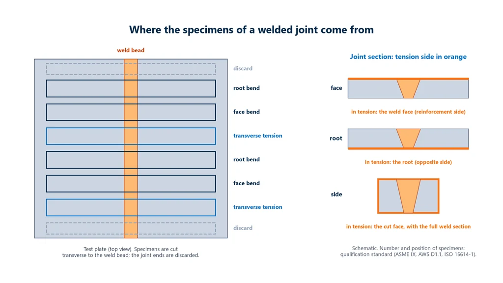
The two most commonly required mechanical tests use specimens cut transverse to the weld bead, so that the weld metal, the heat-affected zone and the base metal are all within the tested length:
- Transverse tensile test (ISO 4136:2022): measures the strength of the joint and records where it fractured. The fracture location (weld metal, heat-affected zone or base metal) is part of the result. ASME IX requires two tensile specimens for procedure qualification.
- Bend test (ISO 5173:2023): bends the specimen 180° around a mandrel and examines the surface in tension for cracks, porosity and lack of fusion. In the face bend, the weld face is in tension; in the root bend, the root is, which reveals lack of penetration; in the side bend, the cross section of the entire joint, used on thick plates. Under ASME IX, below 10 mm thickness 2 face and 2 root bends are used; from 10 to 19 mm, 4 side bends may replace them; from 19 mm up, 4 side bends are required.
The diagram below shows a test plate seen from above, with the specimens cut transverse to the weld bead and the ends discarded, and, on the right, the joint cross section with the side in tension for each type of bend.
Before the bend test, the weld reinforcement is removed flush with the plate, so that it does not create a stress concentration at the transition. Mandrels, the acceptance criteria of each code and the calculation of bend severity are covered in the article on the bend test.
There are also longitudinal specimens, with the axis along the weld bead. In ISO 5178:2019, a round specimen machined entirely from weld metal measures the properties of the deposited metal, without the influence of the base metal. Two other qualification tests do not use a tensile testing machine: macrographic examination (ISO 17639:2022), performed on a ground and etched cross section that shows penetration, fusion and bead profile, and the fracture test (ISO 9017:2017), in which the notched specimen is broken to expose porosity, inclusions and lack of fusion on the fracture surface.
Chart: test specimens by test and standard
The chart below brings together, on one page, the test specimens covered in the previous sections, except the tensile specimens for metals, already shown in the anatomy diagram. Each panel has its own scale; the numbers are the main dimensions of the standard indicated.
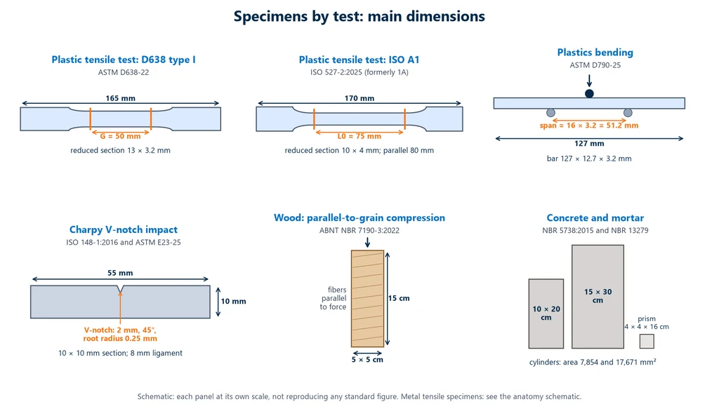
The table summarizes the same content, including metals and welds, for quick reference:
| Test and material | Standard | Main test specimen |
|---|---|---|
| Tensile, metals | NBR ISO 6892-1:2024 | proportional, L0 = 5.65√S0 (≈ 5d0); thin sheet type 2: 20 × 80 mm |
| Tensile, metals | ASTM E8/E8M-25 | 12.5 mm round, L0 of 50 mm (E8) or 62.5 mm (E8M); sheet 12.5 × 50 mm |
| Tensile, plastics | ASTM D638-22 | type I: 165 mm, 13 × 3.2 mm, G = 50 mm |
| Tensile, plastics | ISO 527-2:2025 | A1: 170 mm, 10 × 4 mm, L0 = 75 mm |
| Flexural, plastics | ASTM D790-25 | bar 127 × 12.7 × 3.2 mm, 51.2 mm span |
| Tensile, composites | ASTM D3039/D3039M | constant cross-section rectangular strip, with end tabs |
| Charpy impact | ISO 148-1:2016, ASTM E23-25 | 55 × 10 × 10 mm, 2 mm V-notch, 45°, r = 0.25 mm |
| Hardness | ISO 6506-1, 6507-1, 6508-1 | flat piece; minimum thickness of 8h, 1.5d or 10h to 15h |
| Compression, wood | NBR 7190-3:2022 | 5 × 5 × 15 cm prism, grain parallel to the force |
| Compression, concrete | NBR 5738:2015, NBR 5739:2018 | 10 × 20 or 15 × 30 cm cylinder |
| Mortar | NBR 13279 | 4 × 4 × 16 cm prism |
| Weld | ISO 4136:2022, ISO 5173:2023 | specimens transverse to the weld bead: tensile and bend |
How to prepare the test specimen
A poorly prepared test specimen measures the preparation, not the material. The sequence below applies, with adaptations, to all materials:
- Take it from the right location and in the right direction. Rolled plate has different properties in the rolling direction and in the transverse direction; wood, along the grain and across it; injection-molded plastic, in the flow direction. The product specification states where and in which direction to cut, and the report records it.
- Cut and machine without heating. Heat changes the microstructure of metals and polymers near the cut. Hot cutting or oxyfuel cutting requires leaving a machining allowance, later removed by machining with coolant, as in a metallographic cutting machine. Heavy cuts also work-harden the surface.
- Finish the parallel length. Machining marks transverse to the axis act as small notches. In the Charpy test, the notch is cut with a dedicated tool and checked on a profile projector.
- Measure before testing. Diameter, or width and thickness, at more than one point along the parallel length, with a suitable micrometer or caliper, using the smallest cross section or the average, as the standard requires. In a round specimen, a 1% error in diameter becomes about a 2% error in stress, because the area depends on the square of the diameter.
- Mark L0 with fine scribe lines or ink, without creating a notch, when elongation is measured after fracture.
- Condition. Plastics stay in the standard atmosphere (typically 23 °C and 50% relative humidity) for the specified time; wood has its moisture content measured and the result corrected to 12%; concrete stays in moist curing until the test age.
Fractured test specimen: what the fracture tells you
The fractured test specimen is part of the result. Before accepting the number, the laboratory looks at where and how it broke, because the fracture confirms (or not) that the test measured what it was supposed to.
Metals in tension. A ductile metal forms a neck before breaking, known as necking, and the fracture has a cup-and-cone appearance: a fibrous center and a rim inclined at about 45°. A brittle metal, such as gray cast iron, breaks without necking, on a flat surface perpendicular to the axis. The difference also shows on the curve: ductile fracture comes after a long plastic deformation, brittle fracture almost at the end of the elastic range. The concept is covered in the article on ductility.
Where it broke. Fracture must occur within the parallel length. Fracture inside the grip or at the transition radius indicates excessive clamping, misalignment or a machining defect, and the test is repeated with a new specimen. Even within the parallel length there is a rule for elongation: under ISO 6892-1, it is only valid if the fracture is at least L0/3 from the nearest gauge mark, unless the value obtained already meets the specified minimum. The reason is the same one that makes elongations measured on different gauge lengths incomparable: elongation after fracture is the sum of a uniform component, equal along the entire gauge length, and a component concentrated in the neck. If the neck is close to a gauge mark, part of this concentrated deformation falls outside L0 and the value comes out low.
Concrete. NBR 5739 classifies the appearance of the fractured cylinder into seven types, from A to G. Type A, conical, is that of a well-performed test; types F and G, with fracture next to one of the ends, point to a capping or end preparation problem and do not represent the concrete.
Weld. In the transverse tensile test, fracture in the base metal usually indicates that the joint is at least as strong as the plate; when it occurs in the weld or in the heat-affected zone, the surface is examined for porosity, inclusions and lack of fusion. In the bend test, what is assessed are the discontinuities opened on the surface in tension.
Charpy. In addition to the energy, the fracture gives the percentage of shear area (fibrous, dull) and the lateral expansion, how much the compressed side bulged. A fully bright, crystalline fracture is brittle; a fully fibrous one is ductile.
Interpretation questions
Some misunderstandings come up often in test reports, specifications and audits. The main ones:
Does a smaller test specimen give the same result as the standard one?
For the strength of ductile metals, it usually gives similar values, provided the geometry follows the standard. For elongation, only if the specimen is proportional; a fixed L0 on a smaller cross section changes the number. For brittle materials, equality is not assumed: the size effect makes smaller specimens tend toward higher strengths. In the Charpy test, subsize specimens can only be compared with specimens of the same size.
Can I use the nominal cross section in the calculation?
Only when the standard allows it, as in NBR 5739 for molded cylinders with controlled geometry, or for reinforcing bar, where NBR 7480 (the Brazilian standard for steel bars for reinforced concrete) calculates the area from the bar's mass per meter rather than with a caliper. In all other cases, the cross section is measured on each specimen, because the stress inherits the full error of the area.
Is an elongation of 17% better than one of 15%?
It depends on the gauge length. In the guide to ASTM E8 vs. ISO 6892-1, the same steel specimen gave 17.2% over 50 mm and 15.0% over 62.5 mm. The number only makes sense with the gauge length stated.
Does the test specimen represent the part?
It represents the material in the condition in which it was taken. The part may have regions with different properties (hardened surface, soft core; plate edge; root of a weld bead), stress concentrators and residual stresses that the specimen does not have. That is why the specification defines where the specimen is taken from, and component testing is a different type of test.
Can a test specimen that has already been tested be reused?
In a destructive test, no: once the elastic limit is exceeded, the material in the gauge section has been plastically deformed, work-hardened or cracked, and no longer represents the lot. The exception is measurement only in the elastic range, such as that of the modulus of elasticity, which does not change the specimen. In hardness testing, the same piece receives several indentations, provided the spacing between them is respected.
Can a test specimen that broke in the grip be used?
The recorded strength is, at most, a lower bound, because the section that broke was under stresses that are not those of the test. For the report, another specimen is tested and the cause (clamping, alignment, transition radius) is investigated so that it does not happen again.
Solved exercises
The exercises use the formulas given in the vocabulary section: S0 = π·d0²/4 or a0·b0, L0 = 5.65·√S0 and F = R·S0, where R is the strength of the material in MPa (N/mm²). The estimated force is the figure that determines which machine and which grip to use.
Exercise 1: 12.5 mm round specimen to ASTM and ISO
A steel with a tensile strength of 450 MPa will be tested as a 12.5 mm diameter round specimen. What are the gauge lengths under ASTM E8, E8M and ISO 6892-1, and what maximum force should be expected? And for a 10 mm round specimen under ISO?
- Area: S0 = π × 12.5² / 4 = 122.72 mm².
- Gauge lengths: E8, 4D = 50 mm; E8M, 5D = 62.5 mm; ISO, 5.65 × √122.72 = 5.65 × 11.078 = 62.6 mm, marked as 62.5 mm. The ISO proportional gauge length matches E8M; E8 uses a gauge length 20% shorter.
- Maximum force: Fm = 450 × 122.72 = 55,223 N ≈ 55.2 kN.
- 10 mm round specimen under ISO: S0 = 78.54 mm²; L0 = 5.65 × 8.862 = 50.1 mm; Fm = 450 × 78.54 = 35,343 N ≈ 35.3 kN.
- Machine: 55.2 kN exceeds the capacity of a 50 kN machine, so the 12.5 mm round specimen calls for the 100 to 200 kN range, with 200 kN wedge grips or, if the ends are threaded, grips for threaded specimens. The 10 mm specimen, at 35.3 kN, fits the 5 to 50 kN machine (71% of capacity), with 50 kN pneumatic wedge grips or 200 kN wedge grips.
Exercise 2: thin sheet and plastic
What breaking force should be expected from a sheet of the same steel, in the E8 sheet-type specimen 2.0 mm thick, and from a plastic in the D638 Type I specimen, assuming an illustrative strength of 40 MPa for it?
- Sheet: S0 = 12.5 × 2.0 = 25.0 mm²; Fm = 450 × 25.0 = 11.25 kN. It fits the 5 to 50 kN machine, with 20 kN wedge grips.
- Plastic: S0 = 13 × 3.2 = 41.6 mm²; F = 40 × 41.6 = 1,664 N ≈ 1.66 kN. The right range is the 10 kN single-column machine, with 5 kN wedge grips or lever grips and a 50 mm extensometer, which matches the Type I gauge length.
The 30-fold difference between the steel round specimen and the plastic dogbone shows why the capacity of the machine and the load cell is chosen from the test specimen, not from the material in the abstract.
Exercise 3: compression of concrete and wood
What force breaks a 30 MPa concrete cylinder in the two sizes of NBR 5738 (the Brazilian standard for molding and curing concrete specimens), and a D40 strength class wood prism in compression parallel to the grain?
- Concrete 10 × 20: F = 30 × 7,854 = 235,620 N ≈ 236 kN.
- Concrete 15 × 30: F = 30 × 17,671 = 530,130 N ≈ 530 kN, 2.25 times more, because the area grows with the square of the diameter (1.5² = 2.25). Both sizes are tested in the concrete compression testing machine, and the 15 × 30 requires a much higher capacity.
- D40 wood: the class indicates a characteristic strength of 40 MPa; for a 5 × 5 cm prism, F = 40 × 2,500 = 100 kN. Since the characteristic value is a low value of the distribution, the mean of the specimens lies above it, and the machine needs headroom: 300 kN compression platens on the 100 to 200 kN machine or on the 300 kN machine.
Exercise 4: minimum thickness in the Vickers test
A 0.50 mm sheet receives a Vickers indentation with a mean diagonal of 0.40 mm. Is the reading valid?
- Minimum thickness = 1.5 × 0.40 = 0.60 mm.
- Since 0.50 mm is less than 0.60 mm, the deformation reaches the back face and the reading is influenced by the support. A lower force is needed, one that produces a diagonal of no more than 0.50 / 1.5 = 0.33 mm.
Common mistakes with test specimens
Most results rejected in audits originate in the test specimen, not in the machine:
- Treating sample and test specimen as synonyms in the sampling plan, without stating how many specimens come from each sample.
- Thinking test specimens are only for concrete. Every materials test has its own, with its own standard.
- Comparing elongations from different gauge lengths (4D and 5D, 50 mm and 80 mm).
- Using the nominal dimension instead of the measured one.
- Heating or work hardening during machining, or leaving scratches on the parallel length.
- Gripping the specimen misaligned or with the grip slipping, which shows up as steps and a sawtooth pattern on the curve.
- Accepting fracture outside the parallel length, or elongation with fracture less than L0/3 from the gauge mark, without analysis.
- Changing the specimen size for a brittle material and comparing with the history of the old size.
- Citing a canceled or superseded standard: NBR 5738:1994, ISO 527-2:2012 (with the names 1A and 1B) or old editions of D638 and D790.
- Measuring hardness on a part that is too thin, without checking the minimum thickness.
- For concrete, poorly preparing the end faces, which produces type F and G fractures.
Equipment for testing each specimen
On the universal testing machine (UTM), the test specimen defines the rest of the setup: the grip or fixture that holds it, the capacity of the machine and the load cell, and the extensometer, which is positioned within L0. The software receives the measured cross section and the gauge length and converts force and displacement into stress and strain. In the Biopdi M2 line, the load cell is class 1 per ABNT NBR ISO 7500-1:2023. The panel below shows the machine, the role of each part and the fixtures that correspond to the specimens in this article.
The universal testing machine and the test specimen
The M2 line has single-column models, from 200 N to 10 kN, and dual-column models, from 5 kN to 1,000 kN. With the specimen mounted, each part has a function:

- Moving crosshead applies the force at the rate set by the standard
- Load cell class 1, chosen from the specimen force
- Grips and fixtures hold the ends or support the specimen
- Extensometer measures strain within L0
- BioLab software uses the measured S0 and L0 to calculate stresses
- Control panel and emergency stop position and stop the test
Fixtures by type of test specimen
The fixtures below are mounted on the same machine, depending on the test specimen:
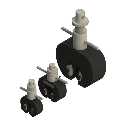
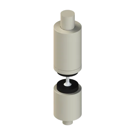
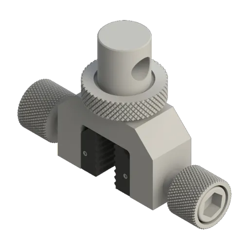
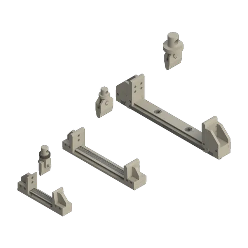
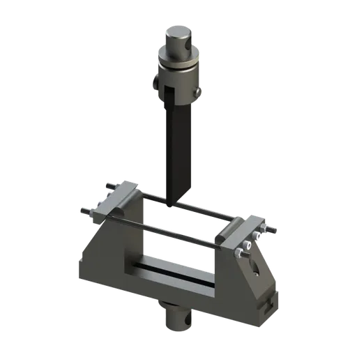
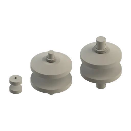
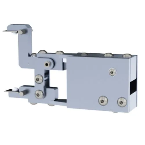
The model is chosen from the estimated specimen force, as in the exercises. Films, wires and small components go on the MBIOI-1P-M2, from 200 N to 1 kN; plastic dogbones and light wood prisms, on the MBIOI-10-M2; sheets, composites and small metal round specimens, on the MBIOII-50-M2; the 12.5 mm steel round specimen, rebar and cables, on the MBIOII-200-M2. The method for each standard is configured in the BioLab software. Concrete cylinders are tested on the electric or hydraulic concrete compression testing machine. To configure the machine for your test specimens, request a quote.
Standards cited
The table lists the standards in this article with the current edition, checked on October 1, 2026 in the ASTM store, the ISO catalog and ABNT catalogs:
| Standard | Subject | Edition |
|---|---|---|
| ABNT NBR ISO 6892-1 | tensile testing of metals at room temperature (Brazilian adoption of ISO 6892-1) | 2024 |
| ISO 6892-1 | tensile testing of metals at room temperature | 2019 |
| ASTM E8/E8M | tension testing of metallic materials | E8/E8M-25 |
| ASTM D638 | tensile properties of plastics | D638-22 |
| ISO 527-2 | tensile properties of molding and extrusion plastics | 2025 |
| ASTM D790 | three-point flexural testing of plastics | D790-25 |
| ASTM D3039/D3039M | tensile testing of polymer matrix composites | 17(2025) |
| ASTM D7264/D7264M | flexural testing of polymer matrix composites | -26 |
| ISO 148-1 and ABNT NBR ISO 148-1 | Charpy impact testing of metals | 2016 and 2021 |
| ASTM E23 | notched bar impact testing of metals | E23-25 |
| ISO 6506-1, ISO 6507-1 and ISO 6508-1 | Brinell, Vickers and Rockwell hardness | 2014, 2023 and 2023 |
| ABNT NBR 7190-1 and NBR 7190-3 | timber structures (Brazilian standards): design criteria and tests on defect-free specimens | 2022 |
| ABNT NBR 5738 | molding and curing of concrete test specimens (Brazilian standard) | 2015 |
| ABNT NBR 5739 | compression testing of concrete cylinders (Brazilian standard) | 2018 |
| ABNT NBR 12655 | concrete: preparation, control and acceptance (Brazilian standard) | 2022 |
| ABNT NBR 7680-1 | cores drilled from concrete structures (Brazilian standard) | 2015 |
| ABNT NBR 13279 | mortar: flexural tensile and compressive strength (Brazilian standard) | 2005 |
| ISO 4136 | transverse tensile test of welded joints | 2022 |
| ISO 5173 | bend tests on welded joints | 2023 |
| ISO 5178 | longitudinal tensile test on weld metal | 2019 |
| ISO 17639 | macroscopic and microscopic examination of welds | 2022 |
| ISO 9017 | fracture test of welds | 2017 |
| AWS D1.1/D1.1M | structural welding code for steel | 2025 |
| ABNT NBR ISO 7500-1 | force verification of testing machines (Brazilian adoption of ISO 7500-1) | 2023 |
Other tests and technical references
Tests performed on the Biopdi universal testing machine



















Related technical references
NBR 5739 concrete compression test: fc calculation and the NBR 7222, NBR 12142 and NBR 6136-2 standards
ABNT NBR 5739:2018 (the Brazilian standard for concrete compression testing), reaffirmed in 2023, covers compression testing of cylindrical concrete specimens: continuous loading at 0.45 ± 0.15 MPa/s until failure and fc = 4F/(πD²), in MPa, to three significant figures. See what it requires of the machine and the specimen, the h/d correction, failure types A to G and the related standards: NBR 7222 (splitting tensile test), NBR 12142 (flexural tensile strength) and NBR 12118, withdrawn in February 2026 and replaced by NBR 6136-2:2026.
Bend test: what it is, types, rebar, welds and standards (ISO 7438)
The bend test bends a specimen around a mandrel to 90° or 180° and checks for cracks. See test types, NBR 7480 mandrels, weld bend testing and standards.
Materials testing: what it is, types, destructive and non-destructive testing, standards and how to choose
Materials testing is the standardized procedure that measures the mechanical, physical, chemical or microstructural properties of a representative sample, or that inspects a part without damaging it. See the five families of tests, the difference between destructive and non-destructive testing, the test specimen, accreditation, the standards and how to choose the right test.
Frequently asked questions
What does test specimen mean?
It is a portion of material with a shape, dimensions and finish defined by a standard, prepared for a test. The standardized geometry makes the stress state known and the result comparable, and it lets you measure strength, elongation or energy without testing the whole part.
What is the standard for test specimens?
There is no single standard: each test has its own. Tensile testing of metals follows ABNT NBR ISO 6892-1:2024 (the Brazilian adoption of ISO 6892-1) or ASTM E8/E8M-25; plastics, ASTM D638-22, ISO 527-2:2025 and ASTM D790-25; Charpy, ISO 148-1 and ASTM E23; timber, NBR 7190-3:2022 (the Brazilian standard for testing timber specimens); concrete, NBR 5738:2015 and NBR 5739:2018 (the Brazilian standards for molding and curing concrete specimens and for concrete compression testing); welds, ISO 4136:2022 and ISO 5173:2023 and the qualification codes.
What size is a test specimen?
There is no single size: each test standard sets its own. Some reference examples are the 10 × 20 cm or 15 × 30 cm concrete cylinder (NBR 5738:2015), the 12.5 mm round steel specimen (ASTM E8/E8M-25), the 165 mm plastic dog-bone specimen (ASTM D638-22), the 55 × 10 × 10 mm Charpy bar (ISO 148-1:2016) and the 5 × 5 × 15 cm timber prism (NBR 7190-3:2022).
How do you make a test specimen?
Take the sample at the location and in the direction required by the product specification, cut or machine it without heating to the geometry of the test standard, finish the gauge section, measure the cross-section and condition the specimen before testing. Concrete and injection-molded plastic are molded, not machined: concrete, under NBR 5738, in consolidated layers inside the mold.
What is the difference between a sample and a test specimen?
The sample is the portion taken from the lot or product to represent it; the test specimen is the piece with the geometry of the standard, prepared from the sample. Several test specimens can come from one sample.
What is the area of a 10x20 test specimen?
7,854 mm² (78.54 cm²), from the formula π·D²/4 with D = 100 mm. At 30 MPa, the failure load is around 236 kN. The 15 × 30 cylinder has 17,671 mm².
How many blows for a concrete test specimen?
For the 10 × 20 cm cylinder with manual rodding, NBR 5738:2015 calls for 2 layers of 12 blows each. The other dimensions and consolidation by vibration are covered in the article on concrete test specimens.
What is the curing time of a test specimen?
For concrete, the test specimen stays at least 24 h in the mold (48 h for prismatic specimens) and then in moist curing at (23 ± 2) °C until the test age, usually 7 and 28 days, under NBR 5738:2015. Metals have no curing, and plastics undergo conditioning at controlled temperature and humidity. The details for concrete are in the article on concrete test specimens.
How many test specimens per m³ of concrete?
There is no rule per cubic meter. NBR 12655:2022 (the Brazilian standard for concrete preparation, control and acceptance) requires sample sets of two test specimens from the same batch for each age; in partial sampling, each lot, of up to 50 m³ in compression members or 100 m³ in members under simple bending, needs at least 6 sample sets. The full calculation is in the article on concrete test specimens.
What is the value of a concrete test specimen?
If the question is about strength, the value is the failure load divided by the area, in MPa, compared with the design characteristic strength (fck): a 10 × 20 cylinder that fails at 236 kN has 30 MPa. If it is about price, it depends on who sells the mold or the test, and this article does not quote prices.
What is test specimen extraction?
It is the removal of a core, a concrete cylinder cut from the finished structure with a rotary drill and diamond core bit, under ABNT NBR 7680-1:2015 (the Brazilian standard for drilled concrete cores). It is used to evaluate the concrete actually in the structure, usually when the molded test specimens did not accept the lot.
What machine is used to break test specimens?
Concrete cylinders are broken in a compression testing machine, electric or hydraulic, under NBR 5739:2018. Metal, plastic, timber and composite test specimens, in tensile, compression, flexural and bend tests, are broken in a universal testing machine, and Charpy specimens in an impact pendulum. The capacity is chosen from the expected force of the test specimen.
What size is a steel tensile test specimen?
In the ASTM E8 standard specimen, round with a 12.5 mm diameter and a 50 mm (4D) gauge length, or 62.5 mm in E8M. Under ISO 6892-1, the original gauge length is 5.65√S0, about 5 times the diameter: 50 mm on a 10 mm round specimen.
Why does a tensile test specimen have wider ends?
So that deformation and fracture happen in the narrow middle section, away from the grips, where the stress is uniaxial and uniform. The fillet radius makes the transition without a sharp corner, so that fracture does not start at the change in cross-section.
What to do if the test specimen breaks outside the gauge section?
If it breaks in the grip or at the fillet, the test is repeated with a new test specimen and the cause is investigated. In tensile testing of metals, elongation is only valid if the fracture is at least L0/3 from the nearest gauge mark, unless the value already meets the specified minimum.
What does the fracture of a broken test specimen indicate?
In metals, a cup-and-cone fracture with necking indicates ductile behavior; a flat fracture without necking, brittle behavior. In concrete, failure types A to G in NBR 5739 distinguish normal failure from failure caused by defects at the ends. In welds, the fracture location is part of the result.
What does a weld test specimen look like?
It is cut from a welded test joint, transverse to the weld bead, at the locations defined by the qualification code. The most requested tests are the transverse tensile test (ISO 4136:2022) and the face, root or side bend test (ISO 5173:2023). Under ASME IX, joints 19 mm thick or more require 4 side bends.
What is the weld test performed on test specimens called?
It is qualification, of the welding procedure or of the welder, under ASME IX, AWS D1.1 or ISO 15614-1 and 9606-1. In it, test specimens cut from the test joint undergo bend testing, transverse tensile testing and, depending on the code, macrographic examination (ISO 17639:2022) or fracture testing (ISO 9017:2017).
What size is a Charpy test specimen?
55 × 10 × 10 mm, with a V-notch 2 mm deep, a 45° angle and a 0.25 mm root radius, under ISO 148-1:2016 and ASTM E23-25. Subsize specimens 7.5, 5 and 2.5 mm thick can only be compared with each other.
How do you mount the test specimen in the machine?
Choose the grip or fixture by the shape and force of the test specimen, clamp one end, zero the force, clamp the other end aligned with the axis without gripping the parallel length, and position the extensometer within L0. Enter the measured cross-section and the gauge length in the software before starting.