
ABNT NBR 7480 is the Brazilian standard that sets the requirements for steel used as reinforcement in reinforced concrete structures, and the current edition is ABNT NBR 7480:2024, fourth edition, dated March 27, 2024. It defines the CA-25, CA-50 and CA-70 bars and the CA-60 wires, and for each grade it requires a minimum characteristic yield strength, a minimum tensile-to-yield strength ratio, elongation, a 180° bend without cracking, a mass per meter within tolerance, a rib geometry, identification, and lot sampling. It is a requirements standard: it states the values the steel must reach, while the test methods come from other standards, such as ABNT NBR ISO 6892-1 (tensile test) and ABNT NBR 17005 (bend test).
In short:
- Current edition: ABNT NBR 7480:2024, 4th edition, March 27, 2024, 17 pages, committee ABNT/CB-028 (Steel industry).
- CA-50: fyk ≥ 500 MPa, fst/fy ≥ 1.10, elongation ≥ 8% over 10φ (or 5% at maximum force), bend over a 3φ mandrel (φ < 20 mm) or 6φ mandrel (φ ≥ 20 mm).
- New since 2007: the CA-70 grade, at 700 MPa, which the 2007 edition did not include.
- Testing: mass per meter, tensile test and bend test, on a universal testing machine with wedge grips and a bend test fixture.
What is the current edition of NBR 7480
The standard's history in the ABNT catalog, distributed by Target and checked on September 30, 2026, has three recent milestones: the new edition of June 2022, a corrigendum of May 2023, and Amendment 1 of March 2024, which produced the consolidated version now sold as "NBR 7480 of 03/2024", with current status. The foreword of the 2024 edition, checked in the full text, states that it is equivalent to NBR 7480:2022 (corrected version of May 31, 2023) combined with Amendment 1 of March 27, 2024, and that it cancels and replaces the 2022 edition. That is why the citation "2022 with Amendment 1:2024" is still seen: the content is the same, but the correct form today is ABNT NBR 7480:2024.
The practical problem is the previous edition, from 2007. Full copies of it circulate as PDFs and still appear among the top search results, and anyone who specifies or accepts steel based on that text applies criteria that have changed. The three differences that most affect the laboratory are:
- CA-50 fst/fy ratio: raised from 1.08 to 1.10. A bar with a ratio of 1.09 passed in 2007 and is rejected today.
- CA-70: the high-strength grade did not exist in 2007.
- Bend test method: the 2007 edition referred to ABNT NBR 6153, now canceled; today the method is ABNT NBR 17005:2021, specific to bars and wires for reinforced concrete.
The standard is sold by ABNT (the Brazilian Association of Technical Standards) and by authorized distributors. The free PDFs in circulation are unauthorized copies and most of them contain the 2007 edition. This guide explains the requirements in our own words and quotes only the essential numbers, with the source where they were checked; to accept or reject a lot, the reference is the purchased standard.
What NBR 7480 requires and what it does not cover
The full title of the standard is Aço destinado às armaduras para estruturas de concreto armado: Requisitos (Steel for the reinforcement of concrete structures: Requirements). It applies to the ordering, manufacture and supply of bars and wires, with or without surface coating. Within that scope, it sets the grades, the mechanical properties, the surface geometry, the mass per meter and its tolerances, product identification, and the rules for lot formation and sampling.
Three boundaries avoid confusion. NBR 7480 is not a test standard: it gives the minimum yield strength, but the tensile test procedure is in ABNT NBR ISO 6892-1. It is not a design standard: the design of reinforced concrete structures is covered by ABNT NBR 6118, which uses the steel specified by NBR 7480. And it does not cover prestressing steel: wires and strands for prestressed concrete follow ABNT NBR 7482 and ABNT NBR 7483. Welded wire mesh has its own standard, ABNT NBR 7481.
The methods that NBR 7480 calls up are in the list of normative references on the catalog page:
- ABNT NBR ISO 6892-1: tensile testing of metallic materials at room temperature (the Brazilian adoption of ISO 6892-1).
- ABNT NBR 17005: bend test of bars and wires for reinforced concrete.
- ABNT NBR 7477: determination of the bond coefficient, which measures the effect of the ribs on bond.
- ABNT NBR 7478: fatigue test of bars, when required.
- ISO 15630-1: international test methods for reinforcing bars, rods and wire, with the particulars of full-section, ribbed test specimens.
Beyond the technical standard, there is the legal obligation: steel bars and wires for reinforced concrete are subject to mandatory certification by Inmetro (Brazil's National Institute of Metrology, Quality and Technology), under Ordinance No. 139/2021, amended by Ordinance No. 501/2024, which added CA-70. The mechanical tests of NBR 7480 are therefore routine work at steel mills, for production control of certified products, and at materials testing laboratories on construction sites in Brazil.
Steel grades: CA-25, CA-50, CA-60 and CA-70
"CA" stands for concreto armado (reinforced concrete), and the number is the characteristic yield strength in the old unit, kgf/mm². CA-50 has an fyk of 50 kgf/mm², about 500 MPa; it does not mean 50 MPa. The standard separates two products by manufacturing route. Bars have a nominal diameter of at least 6.3 mm and are produced only by hot rolling, with no mechanical deformation afterward; Table B.1 of the standard runs from 6.3 to 40 mm. CA-25 is plain, and CA-50 and CA-70 are ribbed. Wires have a nominal diameter of up to 10 mm and are obtained from wire rod by cold drawing or cold rolling; Table B.2 runs from 3.4 to 10 mm. The wire is CA-60, ribbed, used mainly in stirrups, mesh and precast elements. Between 6.3 and 10 mm both products exist, and what determines whether a piece is a bar or a wire is the process, which the grade identifies. Straightening steel supplied in coils is allowed and does not change this classification.
The process explains the curve of each one. A hot-rolled bar has a well-defined yield plateau, followed by work hardening up to maximum force. A cold-drawn wire has already been cold worked during manufacture: it has no plateau, yields continuously and elongates less. That is why the fy of CA-60 is read as the 0.2% offset yield strength rather than at a plateau. The table summarizes the four grades:
| Grade | Product and process | Surface | Minimum fyk |
|---|---|---|---|
| CA-25 | hot-rolled bar | plain | 250 MPa |
| CA-50 | hot-rolled bar | ribbed | 500 MPa |
| CA-60 | cold-drawn or cold-rolled wire | ribbed | 600 MPa |
| CA-70 | hot-rolled bar, high strength | ribbed | 700 MPa |
CA-70 is the grade the 2007 edition did not have. In the Gerdau catalog, checked on September 30, 2026, it is offered from 12.5 to 32 mm, with a yield strength of 700 MPa, a tensile strength of 770 MPa (ratio 1.10) and an elongation of 8% over 10φ. The design advantage is a lower reinforcement ratio in heavily loaded members, such as columns; the consequence for the laboratory is that, at the minimum values, the same bar size yields and breaks at a force about 40% higher than CA-50 (770 versus 550 MPa).
Mechanical requirements: the NBR 7480 table
Four quantities come out of the tensile test, and each one answers a different question about the reinforcement.
- Yield strength, fy: the force at the yield strength divided by the cross-sectional area. The standard requires using as the area that of a cylindrical bar with the same mass per meter as the bar tested, that is, the area obtained from weighing. The minimum is given as a characteristic value, fyk. In an identified lot, every specimen in the sample must reach the value in the table; the statistical estimate of fyk is used only for a lot without heat identification.
- Tensile strength, fst: the maximum force divided by the same area, which corresponds to the ultimate tensile strength (UTS).
- fst/fy ratio: measures the work hardening reserve. A bar that yields and gains almost no strength afterward fractures soon after; with a minimum ratio of 1.10, the reinforcement deforms and cracks the concrete visibly before it fractures.
- Elongation: A is the elongation after fracture, measured over a gauge length of 10 diameters (10φ); Agt is the total elongation at maximum force, elastic plus plastic, measured at the point of Fmáx. Both describe the ductility of the steel, and for CA-50 and CA-70 the standard accepts either criterion.
The table brings together the minimums for the four grades. Every row was checked against Table B.3 of ABNT NBR 7480:2024, in the full text of the standard:
| Grade | Minimum fyk | Minimum fst | Minimum elongation |
|---|---|---|---|
| CA-25 | 250 MPa | 1.20 fy | A = 18% over 10φ |
| CA-50 | 500 MPa | 1.10 fy (1.08 in 2007) | A = 8% over 10φ or Agt = 5% |
| CA-60 | 600 MPa | 1.05 fy, with fst ≥ 660 MPa | A = 5% over 10φ |
| CA-70 | 700 MPa | 1.10 fy (770 MPa) | A = 8% over 10φ or Agt = 5% |
Mass per meter, length, surface and defects
Mass per meter is the first requirement checked and the simplest. The nominal mass per meter comes from the nominal area and the density of steel, 7,850 kg/m³: m' = (π·φ²/4) × 7,850. For 12.5 mm, the area is 122.7 mm² and the mass is 0.963 kg/m. On the sample, a piece of known length is weighed, the mass per meter is calculated, and its deviation from the nominal value is compared with the tolerance for that bar size.
Mass is a requirement because it shows whether the bar contains the steel its size promises: the designer relies on the nominal cross section, and weighing checks that section along the whole length, ribs included. The values for bars, checked against Table B.1 of ABNT NBR 7480:2024, are:
| Bar size φ (mm) | Nominal area (mm²) | Nominal mass (kg/m) | Mass tolerance |
|---|---|---|---|
| 6.3 | 31.2 | 0.245 | ±6% |
| 8.0 | 50.3 | 0.395 | ±6% |
| 10.0 | 78.5 | 0.617 | ±6% |
| 12.5 | 122.7 | 0.963 | ±6% |
| 16.0 | 201.1 | 1.578 | ±5% |
| 20.0 | 314.2 | 2.466 | ±5% |
| 22.0 | 380.1 | 2.984 | ±4% |
| 25.0 | 490.9 | 3.853 | ±4% |
| 32.0 | 804.2 | 6.313 | ±4% |
| 40.0 | 1,256.6 | 9.865 | ±4% |
The CA-60 wires in Table B.2, from 3.4 to 10 mm, all have a mass tolerance of ±6%. Length also has a tolerance: straight bars and wires are supplied in 12 m lengths, at ±0.7%, that is, ±84 mm; other lengths are agreed in the order, at ±1%.
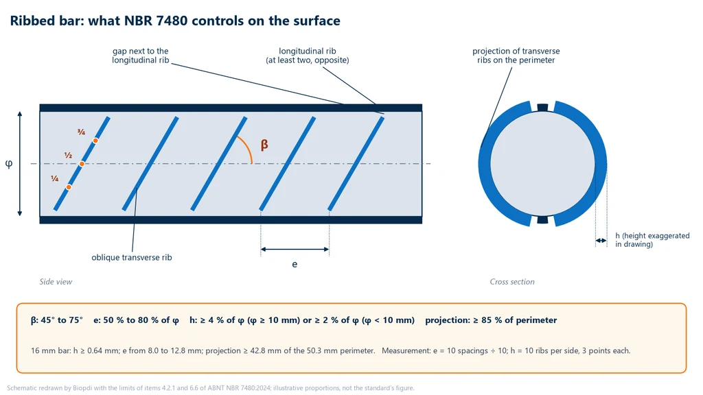
The surface is the other geometric requirement. CA-25 is plain, with no ribs of any kind. CA-50, CA-70 and CA-60 wire are ribbed: oblique transverse ribs, which provide mechanical bearing in the concrete, and at least two continuous, diametrically opposite longitudinal ribs, which prevent the bar from rotating inside it. For CA-50 and CA-70 bars, clause 4.2.1 of the standard sets four dimensions for the transverse ribs:
- Angle β: between the rib axis and the bar axis, from 45° to 75°.
- Mean height h: at least 4% of the diameter for bars of 10 mm or more, and 2% for smaller ones. On a 16 mm bar, h ≥ 0.64 mm.
- Mean spacing e: from 50% to 80% of the diameter, measured along a single line of the surface. On a 16 mm bar, from 8.0 to 12.8 mm.
- Projection: the sum of the transverse ribs projected onto the cross section covers at least 85% of the nominal perimeter: on a 16 mm bar, 42.8 of the 50.3 mm. If the transverse rib touches the longitudinal rib, the requirement is considered met.
Measurement follows clause 6.6. The mean spacing is the length occupied by 10 consecutive spaces, crest to crest, divided by 10. The mean height comes from 10 non-consecutive ribs on each side of the bar, each measured at three points: at the middle and at one quarter and three quarters of its length. The diagram below shows, in side view, the angle, the spacing and these three points, and in cross section the projection of the ribs onto the perimeter:
The effect of the ribs on bond is quantified by the bond coefficient, η, determined according to ABNT NBR 7477. The minimums are in Table B.3: η ≥ 1.0 for bar sizes below 10 mm and η ≥ 1.5 for 10 mm or more, for CA-50, CA-60 and CA-70. Plain CA-25 has η = 1 for all sizes, and the fine series of CA-60 wires (3.4 to 4.2 mm) also takes η = 1, without testing. NBR 6118 uses this coefficient in the anchorage calculation. Bond itself is measured in other tests, described in bond test and pull-out test.
Finally, the steel must be free of defects that impair its use: flaking, corrosion, oil stains, reduced cross section or transverse cracks. Surface oxidation is tolerated if it does not affect the geometry; the standard's practical criterion is that, when rubbed with a coarse cloth or brush, it comes off without leaving signs of corrosion. When in doubt, the way forward is to test the mechanical properties.
Identification, lots and quality certificate
Ribbed bars and ribbed wires carry legible rolled-in relief marks with the producer's name or brand, the category and the nominal diameter, so a piece cut on the job site still shows where it came from. The standard lists what the marking must state, but it does not define a design or a code. Plain CA-25 bars are identified by a tag carrying the same information. Every invoice comes with a quality certificate stating the product, the bar size, the total mass, the standard, the category and the results for the heat or lot: yield strength, tensile strength, the fst/fy ratio, elongation and bend test.
Acceptance is done by lot, and the buyer decides whether to accept the delivery; the inspection in the standard does not cover the steel mill's production control. A lot groups bars or wires of the same origin, category, diameter, coating and geometry, up to 30 t, and from each lot a random sample of specimens at least 1.5 m long is taken. The rule splits into two cases:
- Identified lot, traceable back to production: a sample of 3 specimens, and each one must meet Table B.3; if any fails, the single retest uses 6 new specimens.
- Unidentified lot, with no known heat: the maximum lot mass drops to the value in Table B.4, for example 10 t for 12.5 mm CA-50 and 20 t for 25 mm. The sample has 6 specimens, each one must comply, and the set must also pass a statistical estimator of fyk; the retest uses 12 new specimens.
Before the tensile and bend tests, the lot must also meet the requirements for defects, mass and marking. The flowchart below shows both paths, with the sample and retest for each; the estimator formula and the parameters m and ψ shown in the right-hand branch are explained in "How to interpret the standard":
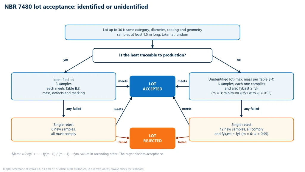
The retest is single: if it fully complies, the lot is accepted; if it fails, the lot is rejected. The wording of the standard allows two readings on mass and marking, because one clause rejects the lot outright on these requirements and another grants a retest for any acceptance requirement. The prudent reading is to run the retest and reject the lot if it also fails. Example 4, further on, applies both criteria to a lot of 6 specimens.
Weldability, bond and fatigue: requirements outside acceptance inspection
Three requirements of NBR 7480 (the Brazilian standard for steel bars and wires for concrete reinforcement) are not part of the routine inspection of each lot. Weldability applies only when the buyer requests it, and then follows Annex C (normative). It limits the chemical composition in the ladle analysis to C ≤ 0.35 %, Mn ≤ 1.50 %, P and S ≤ 0.050 % and Si ≤ 0.50 %, and the carbon equivalent to CE ≤ 0.55 %, with CE = C + Mn/6 + (Cr + V + Mo)/5 + (Cu + Ni)/15. For the analysis made on the product itself, the standard allows small tolerances over these limits, +0.04 on the CE, and the marking of weldable bars is left to the producer. In other words, "weldable CA-50" is not a default guarantee: it is an ordering requirement.
Bond is a characterization test, not an acceptance test. The manufacturer determines η by series and category every three years, alternating the diameters tested, and presents the results to the buyer. For CA-50 and CA-70, the result is valid for similar geometries, with a 10 % tolerance on linear dimensions and angles. Fatigue, under ABNT NBR 7478 (the Brazilian fatigue test method for reinforcing steel), is not an acceptance test either and is carried out only when the buyer requests it.
How to check a sample: mass, tensile test and bend test
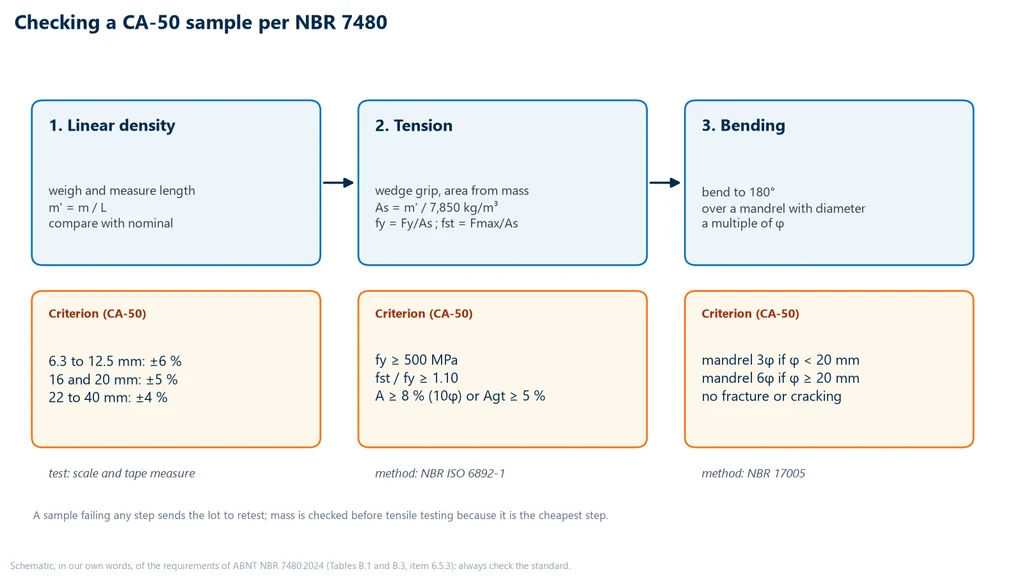
In practice, applying NBR 7480 to a sample means going through three steps in order, each with its own criterion and its own test method standard. The order is not arbitrary: mass is checked first, because it is the cheapest test and because a bar outside the mass tolerance is rejected even if it passes the tensile test. The flowchart below shows the three steps for CA-50, with the criterion of each one and the standard describing the procedure.
Tensile test of rebar
The general procedure, with test speed, reading the curve and calculating the properties, is in the article on the tensile test, and how to read the yield plateau and work hardening is in the stress-strain curve. What changes for rebar are the points where NBR 7480 and ISO 15630-1 depart from the machined test specimen:
- Full-section specimen. The bar is tested as it leaves production: NBR 7480 prohibits machined specimens. Cutting without heating and not welding within the gauge length are preparation precautions, so as not to alter the steel being measured.
- Area from mass. Stresses are calculated with the area of a cylinder having the same mass per meter as the bar: A = m' / 7,850, with m' in kg/m and A in m². Measuring the diameter over the ribs is not part of the calculation.
- Gauge length of 10φ. Elongation after fracture is measured between marks 10 diameters apart: 125 mm on a 12.5 mm bar, 160 mm on a 16 mm bar. Agt is read with an extensometer at maximum force or from marks, as ISO 15630-1 provides.
- Wedge grips. The grips must hold the ribs without slipping and without causing fracture at the jaws. A bar that breaks inside the grip or right next to it does not give a representative elongation.
- Temperature. The test is carried out at room temperature, from 10 °C to 35 °C, the range of ISO 6892-1 (ABNT NBR ISO 6892-1 in Brazil).
- Result. fy, fst, the fst/fy ratio and the elongation are calculated, and each one is compared with the row for the category.
In hot-rolled CA-50, fy is read on the yield plateau, at the upper yield strength. In CA-60, which has no plateau, the stress at 0.2 % permanent strain is used. The standard also allows, as an alternative, the stress under load at 0.5 % strain. The difference between these three criteria, and which one prevails, is covered in the section "How to interpret the standard".
Bend test of rebar
The bend test checks whether the bar can be bent the way it will be on site, into stirrups and hooks, without cracking. The specimen is bent 180° around a mandrel whose diameter is a multiple of the bar size, and the criterion is no fracture and no cracking on the tension face, the outside of the bend.
The method is that of ABNT NBR 17005:2021 (the Brazilian bend test method for metallic materials). It accepts a tensile or compression testing machine, a bending table or other equipment that reproduces the principle, in two arrangements: two supports and a former, or a mandrel with a fixed support and a moving support that wraps the bar around it. The specimen is the bar as supplied, not machined; the test must not be interrupted until the ends are parallel; and the outer face is examined with the naked eye or with corrected vision. NBR 17005 still refers to the mandrel table in the 2007 edition of NBR 7480, and what applies today is Table B.3 of the 2024 edition. Support spacing, types of bend and bend testing of welds are covered in the article on the bend test.
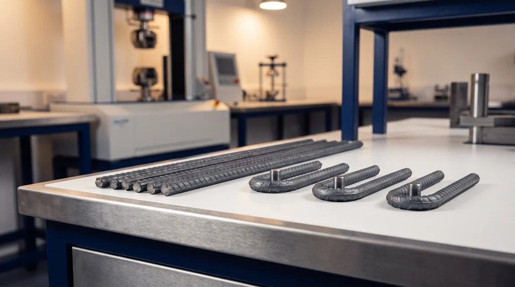
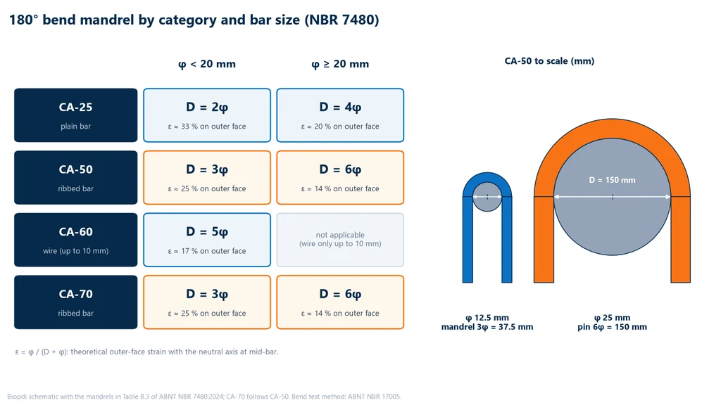
For CA-50, the mandrel is 3φ for bars under 20 mm and 6φ for bars of 20 mm or more, per Table B.3 of the 2024 edition. CA-70 follows the same rule, 3φ below 20 mm and 6φ from 20 mm. CA-25, being more ductile, uses smaller mandrels (2φ and 4φ), and CA-60 wire uses 5φ. The photo shows straight ribbed bars and three specimens already bent 180° around a mandrel: the crack-free outer face of the bend is what the bend test checks.
The test mandrel is not the site mandrel. NBR 6118 (the Brazilian standard for the design of concrete structures) requires bars to be bent on site over larger mandrels than those of the test, so the acceptance test is more severe than the real bend, and that margin is what the requirement guarantees.
How to interpret the standard
NBR 7480 is short and written as requirements, without justifying its choices. The points below are the ones most often misread in the lab and on site, with the physical or statistical reason for each.
Why does the area come from mass and not from the caliper?
Clause 6.5.3 requires stresses to be calculated with the area of a cylinder having the same mass per meter as the bar, A = m' / 7,850. A ribbed bar does not have a single diameter, and the caliper reads a value that depends on where it rests; mass integrates the whole cross section and gives a single, reproducible area. For a 12.5 mm bar weighing 0.960 kg/m, weighing gives 122.3 mm²; a caliper reading 13.5 mm over the ribs would give 143.1 mm², 17 % more. With a yield force of 64.2 kN, fy would drop from 525 to 449 MPa and reject a good steel. The calculated stress is already that of the real steel, and a bar that is too thin is caught by the mass requirement. ISO 15630-1 uses the nominal area when the product standard does not specify otherwise; here, NBR 7480 does.
If yield strength is a characteristic value, why is each bar judged on its own?
fyk is the characteristic value: the one below which only a small fraction of production falls. With 3 specimens there is no way to estimate that fraction, and for an identified lot the standard replaces statistics with a stricter requirement: every specimen reaches the Table B.3 value, and heat traceability covers the rest. For an unidentified lot, each of the 6 specimens must comply and the set must also pass the estimator fyk,est = 2·(fy1 + … + fy(m−1)) / (m − 1) − fym, with the results in ascending order, m = 3 for 6 specimens and m = 6 for 12. With m = 3, the formula becomes fy1 + fy2 − fy3: the mean of the two lowest results minus the distance between the third and that mean. The more scattered the bottom of the sample, the more the estimator drops, down to the floor ψ·fy1, with ψ = 0.92 for 6 specimens and 0.99 for 12. That is why a sample entirely above 500 MPa can still fail, as in example 4.
Which yield value applies: upper yield strength, 0.2 % or 0.5 %?
A hot-rolled bar shows a force peak before the plateau, the upper yield strength, followed by a drop and an almost flat stretch, the lower yield strength. The note to Table B.3 requires the upper value. CA-60 wire, cold-worked, has no plateau, and its yield is conventional: the stress that would leave 0.2 % permanent strain, obtained with a line parallel to the elastic portion. The 0.5 % under-load alternative reads the stress when total strain, elastic plus plastic, reaches 0.5 %, without drawing the parallel line. At 600 MPa the elastic part is about 0.3 % (600 / 200,000), so the two criteria are close but not equal; if they differ, the 0.2 % criterion prevails, and the report states which one was used.
Is elongation A over 10φ or Agt?
A is the elongation after fracture, between marks 10φ apart. It includes necking, concentrated near the fracture, and therefore depends on the gauge length: fixing it at 10φ makes the value comparable across bar sizes. Agt is the total elongation at maximum force, before necking, and measures the uniform strain the bar delivers without losing force, which is the ductility that matters to the structural member. For CA-50 and CA-70, Table B.3 accepts either; CA-25 and CA-60 only have a requirement for A.
What does the number in "CA-50" mean?
It is the characteristic yield strength in kgf/mm², the old unit. The note to Table B.3 allows, for practical purposes, 1 MPa ≈ 0.1 kgf/mm². The exact conversion is 1 kgf/mm² = 9.81 MPa, so 50 kgf/mm² is 490 MPa, and the requirement in MPa is 500, slightly higher. The most common misreading is to treat the number as tensile strength: the 500 MPa of CA-50 and the 600 MPa of CA-60 are yield strengths, and anyone who calls them "minimum strength" compares the maximum test force with the wrong value and forgets the fst/fy ratio.
Why does the bend mandrel grow with bar size?
In the bend, the outer face stretches by ε = φ / (D + φ), with the neutral axis at the middle of the bar. With the mandrel proportional to bar size, strain does not depend on size: 3φ imposes 25 % on any bar. Going from 3φ to 6φ from 20 mm therefore reduces the strain from 25 % to about 14 %. The standard does not explain the choice; the effect is that the thick bar, with taller ribs whose base concentrates strain, is tested in a less severe bend. Between categories, ductility governs: CA-25, with a minimum elongation of 18 %, bends over 2φ; CA-50 and CA-70, with 8 %, over 3φ; CA-60 wire, with 5 %, over 5φ. The matrix below gathers the Table B.3 mandrels with the strain of each and draws two CA-50 mandrels to scale, 37.5 mm and 150 mm:
What does η say about bond?
η is a dimensionless number that expresses how much the bar surface contributes to bond, with the plain bar as the reference, η = 1. In a plain bar, force is transferred to the concrete by adhesion and friction; in a ribbed bar, the transverse ribs bear against the concrete and transfer it mechanically, and that contribution is what η quantifies. The minimum rises to 1.5 from 10 mm, the same bar size at which the minimum rib height doubles, from 2 % to 4 % of the diameter: the geometry of clause 4.2.1 ensures in production the η that the NBR 7477 test (the Brazilian method for determining the bond coefficient) confirms. That is why η is not measured on every lot; the geometry can be checked on the sample, and the test stays with the manufacturer.
Worked examples
The four examples apply the CA-50 requirements. The first three follow the verification flowchart one bar at a time, in order: one case that passes every step and two that fail, one on mass and the other on the fst/fy ratio. The fourth assesses an unidentified lot with the fyk estimator.
Example 1: 12.5 mm CA-50 bar that passes
A 0.500 m piece weighs 0.480 kg. In the tensile test, the yield force is 64.2 kN and the maximum force is 75.0 kN. The gauge length is L0 = 10φ = 125 mm, and after fracture the distance between the marks is Lu = 140.5 mm.
- Mass: m' = 0.480 / 0.500 = 0.960 kg/m. Deviation = (0.960 − 0.963) / 0.963 = −0.3%, within ±6%.
- Area from mass: A = 0.960 / 7,850 = 122.3 mm², slightly below the nominal 122.7 mm², because the bar weighed 0.3% less.
- Yield: fy = 64,200 / 122.3 = 525 MPa, above 500 MPa.
- Strength: fst = 75,000 / 122.3 = 613 MPa; ratio 613 / 525 = 1.17, above 1.10.
- Elongation: A = (140.5 − 125) / 125 × 100 = 12.4%, above 8%.
- Bend test: φ < 20 mm, so the mandrel is 3φ = 37.5 mm; the bar bends to 180° without cracking.
The bar meets every requirement. Lot acceptance, however, follows the standard's sampling rule: in an identified lot, all three specimens must comply, and a single passing bar does not prove on its own that the lot complies.
Example 2: 16 mm bar that fails on mass
A 1.000 m piece of 16 mm CA-50 bar weighs 1.490 kg.
- m' = 1.490 kg/m, against the nominal 1.578 kg/m.
- Deviation = (1.490 − 1.578) / 1.578 × 100 = −5.6%, outside the ±5% tolerance for the 16 mm bar size.
The specimen fails before the tensile test, and the lot goes to retest. Mass is a conformity requirement in its own right because whoever designs the reinforcement counts on the nominal cross-section: 5.6% less steel is 5.6% less force in the structure, even if the material is good. The tensile test would not catch this defect. Since stress is calculated with the area derived from the bar's own mass, this bar, if the steel is good, gives fy above 500 MPa; what reveals the missing cross-section is the weighing.
Example 3: fst/fy ratio below the minimum
A 10 mm CA-50 bar gives fy = 560 MPa and fst = 600 MPa.
- Ratio: 600 / 560 = 1.07, below 1.10: it fails, despite being strong.
- With fst = 610 MPa, the ratio would be 610 / 560 = 1.089: it would pass the 1.08 of the 2007 edition and still fails under the current edition.
The example shows why the edition matters: the same test report leads to opposite decisions depending on which text is used.
Example 4: unidentified lot with 6 specimens
A lot of 12.5 mm CA-50 arrives without heat identification. Under Table B.4, it can be at most 10 t. All 6 specimens pass the mass, bend, fst/fy ratio and elongation requirements, and the yield results, in ascending order, are 508, 512, 540, 546, 551 and 566 MPa.
- Individual results: all above 500 MPa. Each specimen complies.
- Estimator, with m = 3: fyk,est = fy1 + fy2 − fy3 = 508 + 512 − 540 = 480 MPa.
- Floor: ψ·fy1 = 0.92 × 508 = 467 MPa. The estimator, 480 MPa, is above the floor and stands.
- Decision: 480 < 500 MPa. The lot does not comply and goes to retest with 12 new specimens, assessed with m = 6 and ψ = 0.99.
If the three lowest results were 520, 524 and 530 MPa, the estimator would give 520 + 524 − 530 = 514 MPa, and the lot would be accepted. The difference is the scatter at the bottom of the sample: two results close to the minimum and a third well above suggest that production has a fraction below 500 MPa that the sample did not catch. In an identified lot, the sample would be 3 specimens, and it would be enough for each one to exceed 500 MPa.
Breaking force by bar size and machine capacity
The machine is chosen by the highest force the test will require, which is the maximum force of the largest bar size tested: Fmáx = fst × nominal area. The standard gives only the minimum, 550 MPa for CA-50 (1.10 × 500); real bars break above that, and 600 MPa is a prudent reference for sizing. The chart below compares, for each CA-50 bar size, the minimum maximum force and the force at 600 MPa with machine capacities of 200, 300, 600 and 1,000 kN.
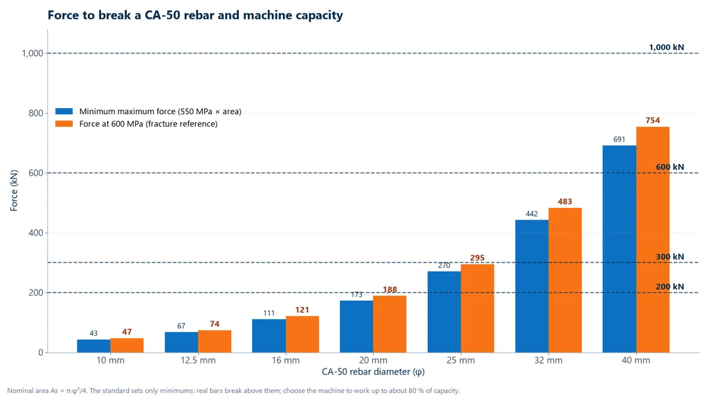
The table gives the same numbers and the recommended model, using the guideline adopted in this article of working up to about 80% of rated capacity to leave headroom for bars stronger than the reference:
| Bar size | Minimum Fy (500 MPa) | Fmáx at 600 MPa | Recommended machine |
|---|---|---|---|
| 10 mm | 39.3 kN | 47.1 kN | 100 to 200 kN |
| 12.5 mm | 61.4 kN | 73.6 kN | 100 to 200 kN |
| 16 mm | 100.5 kN | 120.6 kN | 200 kN |
| 20 mm | 157.1 kN | 188.5 kN | 300 kN |
| 25 mm | 245.4 kN | 294.5 kN | 600 kN |
| 32 mm | 402.1 kN | 482.5 kN | 600 kN (80%) or 1,000 kN |
| 40 mm | 628.3 kN | 754.0 kN | 1,000 kN |
Example 5: choosing the machine for 16, 25 and 32 mm
A laboratory will test 16, 25 and 32 mm CA-50 and, occasionally, 32 mm CA-70. Which capacity is suitable?
- 16 mm: area 201.1 mm². At 600 MPa, Fmáx = 600 × 201.1 = 120,660 N, about 121 kN, or 60% of a 200 kN machine. Even at 700 MPa (140.7 kN) it stays at 70%.
- 25 mm: area 490.9 mm². At 600 MPa it gives 295 kN, 98% of a 300 kN machine: no headroom. The recommended one is the 600 kN machine.
- 32 mm: area 804.2 mm². At 600 MPa it gives 483 kN, 80% of 600 kN; at 700 MPa, 563 kN, 94%. For routine testing of stronger bars, 1,000 kN.
- 32 mm CA-70: the minimum alone is already 770 × 804.2 = 619 kN, above 600 kN. A 1,000 kN machine is mandatory.
Answer: a laboratory covering up to 32 mm, including CA-70, needs the 1,000 kN machine; if large-diameter CA-70 is out of scope, the 600 kN machine covers up to 32 mm at the 80% limit. The grips and the bending fixture follow the chosen capacity.
Common mistakes when applying NBR 7480
The most frequent mistakes are not in the machine, but in reading the standard and preparing the sample:
- Using the 2007 edition. fst/fy ratio of 1.08 for CA-50, no CA-70 grade, and a withdrawn bend test method.
- Treating the grade number as tensile strength. The 500 MPa of CA-50 and the 600 MPa of CA-60 are characteristic yield strength.
- Measuring the diameter with a caliper over the ribs. The real cross-section is checked by linear mass, and that is where the area used to calculate stress comes from.
- Skipping the weighing. A bar outside the mass tolerance fails even if it passes the tensile test, as in example 2.
- Using the wrong mandrel. Using 3φ on a 25 mm bar, where the mandrel is 6φ, bends beyond what is required and can fail a good bar; the opposite passes a bad bar. Nor is the on-site bending mandrel of NBR 6118 (the Brazilian standard for the design of concrete structures) used in the release test.
- Heating, welding or hot-straightening the test specimen. Heat changes the microstructure, and the result no longer represents the lot.
- Accepting a break at the grip. The elongation measured in that case is not representative, and the test must be evaluated or repeated.
- Accepting the lot on one bar. The sample is 3 specimens in an identified lot and 6 in an unidentified one, and all must pass; in the unidentified lot, the fyk estimator also applies.
- Requiring bond or fatigue testing at receiving inspection. The η coefficient is the manufacturer's three-yearly characterization, and fatigue only applies when the buyer requests it.
- Applying NBR 7480 to prestressing steel. Prestressing wires and strands follow NBR 7482 and NBR 7483 (the Brazilian standards for prestressed concrete wire and strand).
- Undersizing the machine. Sizing by the standard's minimum force, instead of a breaking-force reference with headroom, leaves the machine without margin for stronger bars.
Machine for NBR 7480 tests
NBR 7480 tests are performed on the universal testing machine: the tensile test with wedge grips, which hold the full ribbed bar, and the bend test with the bending fixture mounted in place of the grips, on the same machine. The load cell records force, the extensometer measures elongation and the software calculates fy, fst and the ratio between them. The panel below shows the machine, the role of each part in rebar testing and the fixtures used.
The universal testing machine in rebar testing
The M2 line includes single-column models, from 200 N to 10 kN, and dual-column models, from 5 kN to 1,000 kN. In rebar testing, each part of the machine has a function:

- Moving crosshead pulls the bar until fracture
- Load cell measures Fy and Fmáx, class 1
- Wedge grips hold the full ribbed bar
- Extensometer measures elongation and Agt
- Bending fixture bends the bar over the mandrel
- BioLab software calculates fy, fst and fst/fy
Fixtures for rebar testing
The fixtures below are mounted on the same machine, depending on the test:
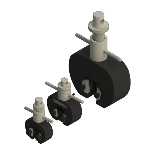
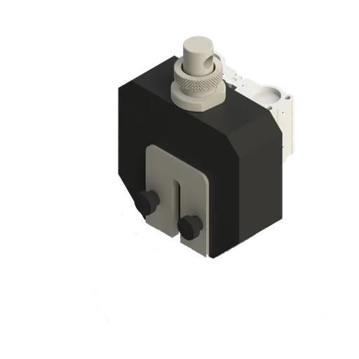
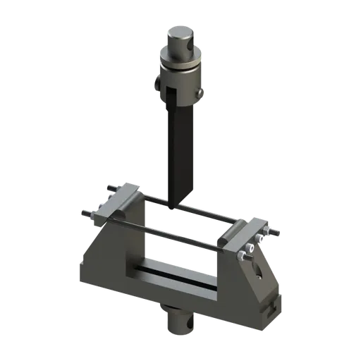
For rebar up to 16 mm, the recommended model is the 100 to 200 kN dual-column universal testing machine (MBIOII-200-M2), whose application range includes rebar and which accepts the 200 kN wedge grips. For larger bar sizes, the floor-standing 300 kN, 600 kN and 1,000 kN models follow the capacity table above; the grips and bending mandrels for these ranges are defined with the machine configuration. The BioLab software records the force × displacement curve, calculates the properties and generates the report. To configure the machine for the bar sizes in your laboratory, request a quote.
Standards cited
The table lists the standards cited in this guide, with the edition and status checked on September 30, 2026 in the ABNT catalog (Target) and in the ISO standards list used by the site:
| Standard | Subject | Edition |
|---|---|---|
| ABNT NBR 7480 | steel for reinforced concrete: requirements | 2024 (current; equivalent to the 2022 edition corrected by Amendment 1) |
| ABNT NBR ISO 6892-1 | tensile testing of metallic materials at room temperature | 2024, with July 2026 erratum |
| ISO 6892-1 | international basis of the tensile test method | 2019 |
| ABNT NBR 17005 | bend testing of bars and wires for reinforced concrete | 2021 |
| ISO 15630-1 | test methods for bars and wires for reinforced concrete | 2019 |
| ABNT NBR 7477 | surface geometry (bond) coefficient | 1982, reaffirmed in 2022 |
| ABNT NBR 7478 | fatigue of bars for reinforced concrete | 2021 |
| ABNT NBR 6118 | design of concrete structures | 2023 |
| ABNT NBR 7482 and NBR 7483 | wires and strands for prestressed concrete | 2020 and 2021 |
| ABNT NBR ISO 7500-1 | verification of the machine's load cell | 2023 |
Other tests and technical references
Tests performed on the Biopdi universal testing machine



















Related technical references
Stress-strain curve: how to read the diagram, key points, formulas and the true stress-strain curve
The stress-strain curve plots stress (σ = F/S0) against strain (ε = ΔL/L0) from a tensile test. Learn to read each point, the formulas, the true curve, Brazilian CA-50 rebar steel, concrete per ABNT NBR 6118 (the Brazilian concrete design standard) and solved exercises.
Tensile test: what it is, step by step, calculations and standards (ISO 6892-1)
A tensile test pulls a specimen axially to fracture to measure yield strength, UTS, modulus and elongation. Calculations, steps, standards and specimens.
Weld test specimen: tensile and bend tests per ASME IX, AWS and ISO
Weld test specimen: how to cut, machine and run tensile and bend tests per ASME IX and ISO 15614-1, with the 3 mm and 95% criteria and examples.
Frequently asked questions
What is NBR 7480?
It is the ABNT standard (the Brazilian standard for steel reinforcing bars) that sets the requirements for steel used as reinforcement in reinforced concrete: grades CA-25, CA-50, CA-60 and CA-70, minimum yield strength, tensile-to-yield strength ratio, elongation, bend test, mass per unit length, surface geometry (ribs), identification and sampling. The current edition is ABNT NBR 7480:2024, which is the 2022 edition as corrected by Amendment 1.
What is the latest update of NBR 7480?
ABNT NBR 7480:2024, fourth edition, dated March 27, 2024. It consolidates the June 2022 edition, the May 2023 corrigendum and Amendment 1 of March 2024. Test reports and specifications should cite "ABNT NBR 7480:2024".
What steel grades does NBR 7480 cover?
Hot-rolled bars CA-25 (plain), CA-50 and CA-70 (ribbed), and CA-60 wires, cold-drawn or cold-rolled. The number gives the characteristic yield strength in kgf/mm²: 50 kgf/mm² corresponds to about 500 MPa.
What is the difference between CA-50 and CA-60?
CA-50 is a hot-rolled bar with an fyk of 500 MPa, a yield plateau and a minimum elongation of 8%. CA-60 is a cold-worked (work-hardened) wire with an fyk of 600 MPa, no yield plateau and lower ductility (minimum elongation of 5%), used mainly for stirrups and welded mesh.
What is CA-70 steel?
It is the high-strength ribbed bar, with an fyk of 700 MPa. It did not exist in the 2007 edition, and its certification is mandatory in Brazil under INMETRO Ordinance No. 501/2024. According to Table B.3 of the standard, the minimum fst/fy ratio is 1.10 (770 MPa for an fyk of 700), with an elongation of 8% over 10φ or an Agt of 5%, and the bend mandrel is the same as for CA-50.
What is the minimum fst/fy ratio for CA-50?
1.10 in the current edition; it was 1.08 in the 2007 edition. The ratio guarantees a work hardening reserve, so the reinforcement deforms and gives warning before it fractures.
What is the bend mandrel diameter for CA-50?
3φ for bars under 20 mm and 6φ for bars of 20 mm or more, with a 180° bend and no fracture or cracking on the tension face. The method is that of ABNT NBR 17005:2021 (the Brazilian bend test method for reinforcing steel).
How much does one meter of 12.5 mm and 16 mm rebar weigh?
0.963 kg/m and 1.578 kg/m, with tolerances of ±6% and ±5%, per Table B.1 of ABNT NBR 7480:2024. The nominal mass is the nominal area times 7,850 kg/m³.
Which standard should be used for the rebar tensile test?
NBR 7480 gives the limits, and the procedure follows ISO 6892-1 (ABNT NBR ISO 6892-1 in Brazil), with the specific provisions for full-section ribbed bars from ISO 15630-1. Stresses are calculated using the area of a cylinder with the same mass per meter as the bar, and the actual cross section is controlled through the mass per unit length.
What testing machine is needed to test rebar?
It depends on the largest bar diameter. At 600 MPa, a 16 mm bar breaks at about 121 kN, a 25 mm bar at about 295 kN and a 32 mm bar at about 483 kN. A 200 kN machine covers up to 16 mm; 25 and 32 mm require 600 kN, and 40 mm or 32 mm CA-70 require 1,000 kN.
Where can I download NBR 7480 as a PDF?
The standard is sold by ABNT and authorized distributors. The free PDFs in circulation are unauthorized copies and are usually the 2007 edition, whose criteria differ from the current ones.
Does NBR 7480 apply to welded wire mesh and prestressing steel?
No. Welded wire mesh follows ABNT NBR 7481; wires and strands for prestressed concrete follow ABNT NBR 7482 and ABNT NBR 7483. NBR 7480 covers bars and wires for reinforced concrete.