
The peel test measures the force per unit width needed to progressively separate two bonded materials, at least one of them flexible, at a constant angle (90°, 180° or T) and constant speed. The result, the peel strength, is the average force over the steady section divided by the width, in N/mm, N/25 mm or lbf/in.
The same test also goes by the names peel strength test and peel adhesion test. It should not be confused with cathodic disbondment, a corrosion test for pipeline coatings under cathodic protection, with the ISO 11343 impact wedge-peel test, which drives a wedge at high speed, or with the pull-off test for paints and mortars, which pulls off a dolly in tension and gives the result in MPa. In this guide you will find what the test measures, the geometries, the formula with the calculation window of each standard, the unit conversion table, the ASTM and ISO standards with editions checked on 10/13/2026, the procedure on the universal testing machine, worked examples, the failure modes, and the difference between peel, shear and tension.
What the peel test measures
The peel test measures the resistance of a bonded joint to progressive separation, when the load is concentrated along a narrow line, the peel front, that advances through the adhesive. This is what happens when you pull a tape off a box, open the sealed lid of a yogurt cup or separate a layer of a laminate: at each instant, only a very narrow strip of adhesive is working, and the rest of the bonded area carries no load, waiting for the front to arrive.
That is why the result is a force per width and not a stress. In a tensile or shear test, the force is distributed over the entire bonded area, and the result is force divided by area, in MPa. In a peel test, the resisting area is the specimen width times a strip a few tenths of a millimeter wide at the front, and that strip cannot be measured. The width can: doubling the width doubles the force, while increasing the bonded length does not change the force, only the test time. The stress that actually exists at the front, called peel stress, is very high and localized, which is why bonded joints fail easily when loaded this way.
The test records the force along the crosshead displacement and delivers a set of results:
- Initial peak: the force to initiate peeling, usually above the plateau, because it includes crack opening and the settling of the arm.
- Average force over the steady section: the basis of the main result.
- Plateau maximum and minimum: show how uniform the bond is; a wide range indicates poorly distributed adhesive or stick-slip peeling.
- Energy: the area under the curve over the measured section, used in adhesive research.
- Failure mode: where the separation occurred, whether at the interface, within the adhesive or in the adherend itself.
The flexible adherend is the part that bends during the test. ISO 11339:2022 treats as flexible an adherend that can be bent to 90° without cracking; in practice, films, fabrics, paper, rubber, tapes and thin metal sheets, from 0.5 to 0.7 mm. The test has a limitation that the standards themselves state: ASTM D3330, for tapes, notes that peel results do not normally provide design information, because there is no direct relationship between the measured number and a functional requirement of the product. The test is for comparing adhesives, batches, substrates and surface preparations tested the same way and for quality control, not for sizing a joint.
Peel force and peel strength
The peel force is the recorded force, in newtons; the peel strength is that force divided by the specimen width, in N/mm. The distinction matters because data sheets and reports use both. A 25 mm tape that peels at 10 N has a peel force of 10 N and a peel strength of 0.40 N/mm; the same tape cut to 12 mm would peel at about 4.8 N, without any change in the adhesive. Comparing forces from specimens of different widths, without dividing by the width, is a common mistake. "Peel adhesion" and "peel resistance" are used as synonyms for peel strength.
Types of peel test: 90°, 180°, T-peel, floating roller and drum
The types of peel test differ in the angle between the peeled arm and the substrate and in the fixture that holds that angle: 180°, 90°, T-peel, floating roller, climbing drum and free-rotating drum. The angle is not a detail: it changes the measured force for the same adhesive, as the calculation section shows. The diagram below shows the five most used geometries, with the rigid substrate in gray, the flexible adherend in orange, the bond line in blue and the force F applied by the machine.
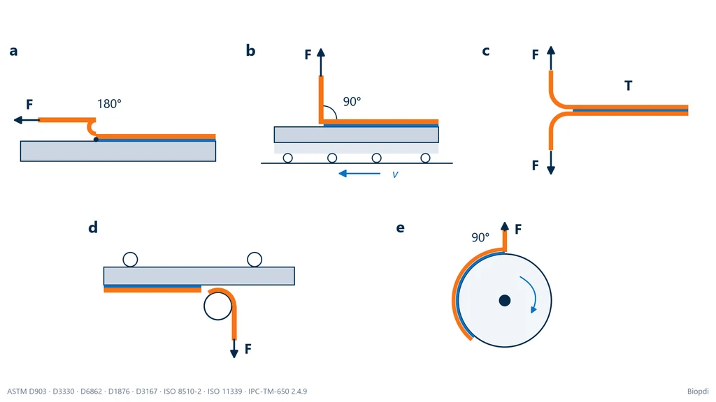
The table summarizes what holds the angle in each geometry and where it is used:
| Geometry | Adherends and angle | Standards | Typical use |
|---|---|---|---|
| 180° | flexible on rigid; the arm folded back on itself sets the angle | ASTM D903, D3330 (method A), ISO 8510-2, ISO 29862 | tapes, labels, laminates |
| 90° | flexible on rigid; a sliding table holds the angle | ASTM D6862, D3330 (method F), D6252, FINAT FTM 2 | labels, coatings, arms that crack at 180° |
| T-peel | flexible to flexible; angle not controlled | ASTM D1876, ISO 11339 | laminates, films, bonded thin sheets |
| Floating roller | flexible on rigid; the roller sets the bend radius | ASTM D3167, ISO 4578 | structural adhesives on metal |
| Climbing drum | facing on core; the drum winds up the arm | ASTM D1781 | sandwich panels |
| Free-rotating drum (peel wheel) | metal foil on dielectric; the drum rotates and holds 90° | IPC-TM-650 2.4.9 | flexible circuits, copper-clad laminate |
180° peel test
In the 180° peel test, the flexible adherend is folded back on itself and pulled parallel to the substrate, in the direction opposite to the still-bonded part. On the machine, the rigid plate with the tape is held in the lower grip, vertically, and the free end of the tape, folded down, goes into the upper grip. This is the standard geometry for pressure-sensitive tapes: ASTM D3330 method A bonds the tape to a stainless steel plate and peels it at 180°, and ISO 29862, for self-adhesive tapes, runs all its methods at 180°. ASTM D903 and ISO 8510-2 apply the same geometry to adhesive bonds with a flexible adherend on a rigid substrate. The point that causes the most errors is kinematic: for every millimeter the crosshead rises, the front advances half a millimeter, because the folded arm unwinds on both sides of the fold.
90° peel test
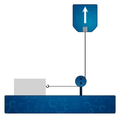
In the 90° peel test, the flexible arm leaves perpendicular to the substrate, and a fixture moves the substrate horizontally so that the front always stays under the grip. Without this fixture, the angle would change as the front advances. The classic solution is a sliding table on rollers, connected to the crosshead by cable and pulley, which moves horizontally by the same amount the crosshead rises. According to Impact Solutions, a laboratory that uses this setup, the typical configuration is 300 mm/min with five specimens 20 mm wide and the result in N/25 mm. The standards are ASTM D6862 (adhesives, flexible on rigid), ASTM D3330 method F (tapes), ASTM D6252 (labels) and FINAT FTM 2.
The 90° geometry is the choice when the arm cannot withstand the 180° fold. The official abstract of ISO 8510-1, the former ISO 90° standard, said exactly that: the method was intended for adherends that crack or delaminate if bent through 180°. That standard was withdrawn by ISO without a replacement, but the criterion still applies. At 90°, the crosshead travels the same distance as the front.
T-peel (ASTM D1876 and ISO 11339)
The T-peel is the peel test between two flexible adherends: the open ends go one into each grip and the bonded part sticks out sideways, forming a T. Since neither adherend is rigid, the angle is not controlled: it depends on the stiffness of the two arms and adjusts itself during the test. For this reason the T-peel compares adhesives well, but the number depends heavily on the thickness and material of the arms. ASTM D1876 uses specimens 25 mm wide and a crosshead speed of 254 mm/min; ISO 11339:2022, according to the public preview of the standard, prefers a 25 mm width, at least five specimens and arms of 0.5 mm steel or 0.7 mm aluminum. These are thicknesses that bend without cracking and still give a stable curve.
In the photo, two aluminum strips bonded face to face: the open ends are held one in the upper grip and the other in the lower grip, and the still-bonded part sticks out sideways, forming the T. When the grips move apart, the bond line opens exactly at the junction, and the crosshead travels twice as far as the front advances, as in the 180° test.
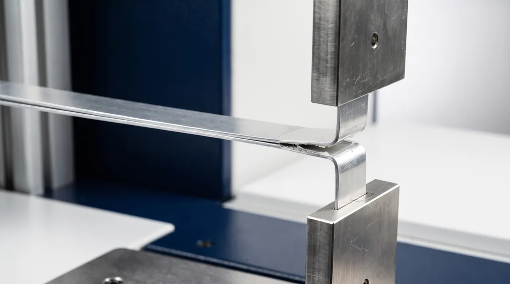
With metal arms, much of the T-peel energy goes into plastically bending the metal rather than separating the adhesive; the same adhesive gives different numbers with aluminum of different thicknesses. That is why the standard fixes the arm thickness and why T-peel results can only be compared with the same adherend material and thickness.
Floating roller and climbing drum
In the floating roller test, the flexible arm wraps around a roller that sets the bend radius and the angle, which makes the test suitable for structural adhesives on metal. The rigid plate rests on rollers and can move, and the flexible arm, after wrapping around the roller, goes to the grip. The standard is ASTM D3167-10(2025), which sets standard thicknesses of 0.63 mm for the flexible adherend and 1.63 mm for the rigid one when the specification does not define others, and ISO 4578:1997, current and confirmed by ISO in 2023. D3167 itself notes that its test is more severe than the climbing drum test, because the peel angle is larger.
The climbing drum (ASTM D1781-98(2021)) winds the flexible arm onto a drum that climbs up the plate as peeling advances. It is the test for sandwich panel facings and for thin sheet bonds to a core, common in the aerospace industry, and the standard presents it as a comparative test. The result is a torque per width, calculated from the force and the drum radius, and it cannot be compared with 90° or 180° results.
Peel wheel: the free-rotating drum test
The peel wheel test is the 90° peel of a metal foil bonded to a freely rotating drum: when the foil is pulled upward, the drum rotates and always brings the front to the top, where the angle is 90°. The method is IPC-TM-650 2.4.9 (revision E, 2014), for the peel strength of flexible dielectric materials, such as the copper of flexible circuits. IPC uses as reference fixture a drum 6 in (152 mm) in diameter, known as the "German wheel", a speed of 50.8 mm/min (2 in/min), strips of 3.2 mm (etched) or 12.7 mm (cut), at least 57.2 mm peeled with the first 6.4 mm discarded, and requires the measured force to fall between 15% and 85% of the range used.
The peel wheel is not the climbing drum. Some pages treat the two as synonyms, but in the free-rotating drum the substrate is bonded to the drum and the foil comes off it; in the climbing drum, the drum winds up the arm and climbs up the plate. The previous English page from Biopdi repeated this confusion, corrected here.
How to choose the geometry
The choice starts with the adherends and follows the customer's specification:
- Tape or label on a plate: 180° (D3330 method A, ISO 29862, FINAT FTM 1), or 90° when the product will be removed at an angle close to that (D3330 method F, D6252, FINAT FTM 2).
- Adhesive with a flexible adherend on a rigid substrate: 180° (D903, ISO 8510-2) or 90° (D6862) if the arm cracks or delaminates at the fold; floating roller (D3167, ISO 4578) for structural adhesives on metal.
- Two flexible adherends: T-peel (D1876, ISO 11339).
- Sandwich panel facing: climbing drum (D1781).
- Copper and foils on flexible circuits: IPC-TM-650 2.4.9.
- Flexible package seals (seal peel): ASTM F88/F88M-23, which measures the strength of the package heat seal and reports the maximum force and, when useful, the average.
How to calculate peel strength
Peel strength is the average force over the steady peeling region divided by the specimen width: P = F̄ / b, in N/mm. The initial peak and the final region are left out of the average. Using the maximum force, as some pages did, and as the former English version of this article did, overstates the result and is not what adhesive standards require. The official ASTM D1876 summary refers to the strength over a specified length of bond line after the initial peak, and ISO 11339:2022, according to the public preview, averages about 100 mm of peeled length, discarding the first 25 mm and the last 25 mm.
The chart below shows the curve from Example 1 in this article, a 25 mm tape peeled at 180°. The force rises to an initial peak of 14 N (region 1), drops to a plateau that oscillates around 10 N (region 2) and falls sharply when the tape runs out (region 3). The shaded band is the calculation window, between 50 and 150 mm of crosshead displacement, and the top axis shows the length actually peeled, which is half the displacement.
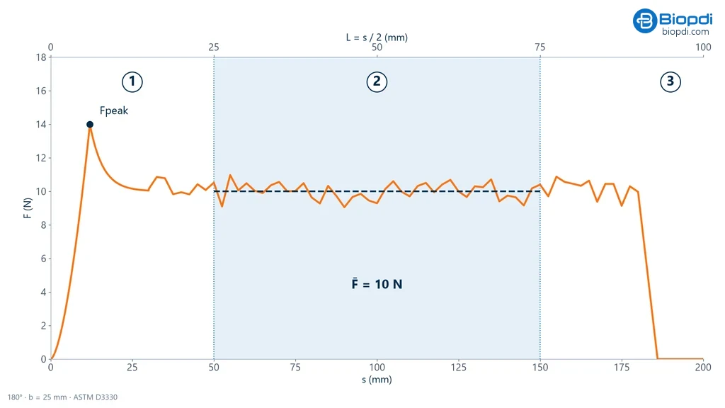
Each standard defines the window in its own way. The table brings the rules together, with the source of each one; those that come from equipment manufacturers and laboratories should be checked against the purchased standard before setting up the test:
| Standard | Speed | Averaging region | Source of the rule |
|---|---|---|---|
| ASTM D1876 (T-peel) | 254 mm/min (10 in/min) | at least 127 mm peeled after the initial peak | ASTM summary; Universal Grip |
| ISO 11339:2022 (T-peel) | 100 mm/min (lower for some adherends) | about 100 mm, excluding the first and last 25 mm | public preview of the standard |
| ASTM D3330 method A (tape, 180°) | 300 mm/min (12 in/min) | discards the first 25 mm; average over the next 50 mm | Mecmesin |
| IPC-TM-650 2.4.9 (drum) | 50.8 mm/min (2 in/min) | discards 6.4 mm; minimum of 57.2 mm | IPC text, rev. E |
| FINAT FTM 1 and FTM 2 | 300 mm/min | according to the method | Mecmesin |
Crosshead displacement and peeled length
At 180° and in the T-peel, the crosshead travels twice the peeled length; at 90° with a sliding table, it travels the same distance. The reason is geometric: at 180°, the end held in the grip moves away from the peel front on both sides of the fold, so each millimeter of tape that comes loose appears twice in the crosshead travel. In the T-peel, both arms move away from the junction at the same time, with the same effect. In practice, this changes the software setup: if the standard says to discard the first 25 mm peeled, at 180° the window starts at 50 mm of crosshead travel. In D1876, a crosshead speed of 254 mm/min makes the peel front advance at 127 mm/min. Forgetting this factor shifts the calculation window into the initial peak or beyond the bonded region.
Why 90° and 180° give different numbers
For the same adhesive, the force at 180° is lower than the force at 90°, and the explanation lies in energy. When the front advances a distance Δa, the adhesive consumes an energy per unit area G, the fracture energy of the joint; the applied force does work that depends on the angle θ between the arm and the substrate. For an arm that does not stretch, the balance gives G = (F/b)(1 − cos θ), the relationship used in the peel test protocol of ESIS (European Structural Integrity Society), published by Imperial College. At 90°, 1 − cos θ equals 1; at 180°, it equals 2. The same energy appears with half the force at 180°.
Kendall (Journal of Physics D, 1975) added to this balance the elastic energy of the stretching arm, (F/b)(1 − cos θ) + F²/(2b²dE) = G, where d is the thickness and E the modulus of the arm. In arms that bend plastically, such as thin metal sheets, a large part of the energy goes into bending the arm, and the simple equality no longer holds. The practical consequence is a single one: values from different angles cannot be converted into one another, and every peel result is reported with its angle.
Stick-slip and serrated curves
Some joints do not peel continuously. The front sticks, stores energy, jumps forward all at once and sticks again, and the curve becomes a sawtooth of peaks and valleys: this is stick-slip, which IPC-TM-650 2.4.9 calls zipper failure. In these cases, the plateau average is still the result, but the report should also include the maximum and minimum, and the scatter is no longer a minor detail. ASTM D5170-98(2021), for T-peel of hook-and-loop fasteners, which naturally have a serrated curve, provides two calculations that are not equivalent to each other, and the report must state which one was used. The same care applies when comparing technical data sheets.
Peel strength units and conversions
Peel strength units are force per width: N/mm (equal to kN/m) in SI, N/25 mm and N/cm in tape data sheets, and lbf/in or oz/in in US data sheets. They all measure the same quantity; what changes is the reference width. The conversion starts from two exact definitions, 1 lbf = 4.4482216 N (NIST) and 1 in = 25.4 mm, and the calculations are Biopdi's:
| Unit | In N/mm | In lbf/in | Where it appears |
|---|---|---|---|
| 1 N/mm = 1 kN/m | 1 | 5.710 | ASTM and ISO standards in SI, structural adhesives |
| 1 N/cm (= N/10 mm) | 0.1 | 0.5710 | European tape data sheets |
| 1 N/25 mm | 0.04 | 0.2284 | tapes, labels, packaging (FINAT) |
| 1 N/in | 0.03937 | 0.2248 | data sheets that measure on a 1 in strip |
| 1 N/m | 0.001 | 0.005710 | fracture energy (1 N/m = 1 J/m²) |
| 1 lbf/in | 0.17513 | 1 | US data sheets, ASTM in inch-pound units |
| 1 oz/in | 0.010945 | 0.0625 | US tape data sheets |
| 1 gf/25 mm | 0.000392 | 0.00224 | low-adhesion packaging |
For a quick mental check: 1 N/mm = 25 N/25 mm = 10 N/cm = 1,000 N/m = 5.71 lbf/in = 91.4 oz/in. Three pitfalls come up often. The first is treating 25 mm as if it were 1 in: 1 N/25 mm equals 1.016 N/in, and the 1.6% difference shows up in conversion calculators that make this approximation. The second is reading N/mm as MPa: N/mm is force per width and MPa (N/mm²) is force per area, different quantities that cannot be converted into one another. The third is converting the unit and assuming the method was converted too: a value in oz/in for a tape at 180° is still a 180° value, and cannot be compared with a 90° value in N/25 mm.
Value ranges help put the numbers in scale. According to Mecmesin, medical packaging with controlled opening falls between 2 and 5 N/25 mm, and high-adhesion protective films exceed 15 N/25 mm. In a 2026 study of structural adhesives on stainless steel, a polyurethane reached 5.41 N/mm in the floating roller test (Pedroso et al., Journal of Mechanical Engineering and Manufacturing, 2026).
Peel test standards
The peel test standard is chosen by product and geometry: tapes follow ASTM D3330 or ISO 29862; adhesives, ASTM D903, D1876, D6862 and D3167 and ISO 8510-2 and 11339; labels, ASTM D6252 and FINAT; flexible circuits, IPC-TM-650 2.4.9. The table gives the edition and status checked on 10/13/2026 in the ASTM store and the ISO catalog:
| Standard and edition | Geometry | What it covers |
|---|---|---|
| ASTM D903-98(2025) | 180° | peel or stripping strength of adhesive bonds, comparative test |
| ASTM D1876-08(2023) | T | adhesives between flexible adherends |
| ASTM D3330/D3330M-04(2025) | 180° and 90° | pressure-sensitive tapes, methods A to F |
| ASTM D6862-11(2021) | 90° | adhesives, flexible to rigid |
| ASTM D3167-10(2025) | floating roller | adhesives, flexible to rigid, on metal |
| ASTM D1781-98(2021) | climbing drum | sandwich panel facings |
| ASTM D6252/D6252M-98(2025) | 90° | pressure-sensitive labels |
| ASTM F88/F88M-23 | seal tensile | seal strength of flexible packaging |
| ASTM D5170-98(2021) | T | hook-and-loop fasteners |
| ISO 8510-2:2006 | 180° | adhesives, flexible to rigid (confirmed in 2025) |
| ISO 11339:2022 | T | adhesives between flexible adherends |
| ISO 29862:2024 | 180° | self-adhesive tapes, methods 1 to 4 |
| ISO 4578:1997 | floating roller | high-strength bonds (confirmed in 2023) |
| IPC-TM-650 2.4.9, rev. E (2014) | 90°, drum or sliding table | metal foil on flexible dielectric |
| FINAT FTM 1 and FTM 2 | 180° and 90° | self-adhesives and labels (Europe) |
Three standards frequently cited online are no longer valid. ISO 8510-1, for 90° peel, was withdrawn without a replacement; anyone who needs 90° today uses ASTM D6862 or D3330 method F. ISO 11339:2010, which Google still shows in results for "t peel test", was replaced by the 2022 edition. ISO 29862:2018 was replaced by the 2024 edition. It is also common to see ISO 4578 described as withdrawn: the 1997 edition is still current, confirmed in 2023. At ASTM, D3167 has a revision in progress, and the edition to use is still the 2010 one, reapproved in 2025.
Brazilian standards. There is no general ABNT standard (ABNT is the Brazilian standards body) for peel testing of adhesives equivalent to D903, ISO 8510-2 or ISO 11339; laboratories in Brazil use the ASTM and ISO standards. Electrical insulating tapes have test methods, including adhesion, in ABNT NBR NM 60454-2 (the Mercosur standard adopted in Brazil, based on IEC 60454-2), whose edition and status were not confirmed in the ABNT catalog as of the date of this article. ABNT NBR 11003, the Brazilian standard for paint adhesion, uses adhesive tape on X-cut and cross-cut patterns, but it is a visual rating test, covered in the article on the bond test.
How to perform a peel test on a universal testing machine
On a universal testing machine, the peel test consists of fixing the substrate or one of the adherends, clamping the free end of the flexible arm in the grip, pulling apart at constant speed and recording the force × displacement curve until the end of the bonded region. The machine is of the CRE type (constant rate of extension), the same used in tensile testing, with a low-capacity load cell and the fixture for the chosen geometry. The general procedure, which each standard details:
- Prepare the surface of the substrate as the standard or the adhesive manufacturer specifies: cleaning with the specified solvent, abrasion or primer. In D3330, the standard panel is stainless steel with a defined finish.
- Assemble the test specimen with the width given in the standard (25 mm is the most common) and an unbonded tab at the end for the grip. For tape, application is done with a roller of defined mass: 2 kg in D3330, according to Universal Grip.
- Observe the dwell time between application and testing. The adhesion of pressure-sensitive tape increases with contact time, and data sheets often give values at 15 or 20 min and at 72 h, which cannot be compared with each other.
- Condition in the atmosphere specified by the standard, usually 23 °C and 50% relative humidity.
- Clamp and align: the panel or fixed adherend in one grip or in the fixture, the arm tab in the other grip, without twisting, with the line of force in the plane of the specimen.
- Set the speed given in the standard and zero the force with the specimen mounted, unloaded.
- Record the full curve, until the length required by the standard has been peeled.
- Calculate the average over the window defined in the standard, remembering the crosshead factor of 2 at 180° and in the T-peel, and divide by the width.
- Record the failure mode of each specimen and discard those that slipped in the grip or peeled off at an angle.
- Report: standard and edition, geometry and angle, width, substrate and preparation, dwell time, speed, temperature, individual values, average, maximum, minimum, scatter and failure mode. The number of specimens is the one in the standard: at least five in ISO 11339:2022; for D1876, UnitedTest cites ten.
The test does not use an extensometer: what matters is the force and the peeled length, which comes from the crosshead displacement.
Load cell and grips
Peel force usually ranges from fractions of a newton to a few tens of newtons, far below the capacity of a machine sized for tensile testing of metals. The load cell must be chosen for the expected force: IPC-TM-650 2.4.9 requires the reading to fall between 15% and 85% of the range used, a rule that serves as a reference for the other methods. An oversized load cell reads small forces with high relative error and masks the oscillations of the plateau. The grip for the flexible arm must hold without cutting or slipping; grips with smooth or rubber-faced jaws are common for tape and film.
Worked examples of peel strength
The examples below are illustrative, with numbers consistent with published ranges, and the calculations are Biopdi's. The conversion factors come from the units table.
1. Tape at 180° (in the style of ASTM D3330 method A). A 25 mm wide tape, applied to stainless steel, is peeled at 300 mm/min. After discarding the first 25 mm peeled (50 mm of crosshead travel), the average over the next 50 mm (from 50 to 150 mm of crosshead travel) is 10.0 N, as in the curve shown above. P = 10.0 / 25 = 0.400 N/mm = 10.0 N/25 mm = 4.00 N/cm = 400 N/m. In US units: 0.400 × 5.710 = 2.28 lbf/in and 0.400 × 91.36 = 36.5 oz/in. The initial 14 N peak is not included in the calculation; if it were, the result would be 0.56 N/mm, 40% higher.
2. T-peel (ASTM D1876). A 25.4 mm (1 in) test specimen, crosshead at 254 mm/min, average of 38.1 N over the 127 mm peeled after the initial peak. P = 38.1 / 25.4 = 1.50 N/mm = 1.50 kN/m; in US units, 1.50 × 5.710 = 8.57 lbf/in. To peel 127 mm, the crosshead travels 254 mm, because the peel front advances at 127 mm/min: the useful part of the test lasts about 1 min after the peak.
3. Why 90° and 180° give different numbers. A tape measures 0.50 N/mm at 90° and 0.25 N/mm at 180°. By energy: G(90°) = 0.50 × (1 − cos 90°) = 0.50 × 1 = 0.50 N/mm = 500 J/m²; G(180°) = 0.25 × (1 − cos 180°) = 0.25 × 2 = 0.50 N/mm = 500 J/m². The adhesive consumes the same energy; it is the force that changes with the angle. The equality holds for an arm that neither stretches nor bends plastically; in real, viscoelastic tapes, the ratio between the two angles departs from 2, which is why one value is not converted into the other.
4. Converting a technical data sheet. A US data sheet gives 180° adhesion of 40 oz/in. In SI: 40 × 0.010945 = 0.438 N/mm = 10.9 N/25 mm. If someone converts per inch and writes the result as if it were per 25 mm, they get 0.438 × 25.4 = 11.1 N, 1.6% higher. Conversion changes the unit, not the method: the value is still a 180° value, with the dwell time and substrate of the data sheet.
5. Choosing the load cell. A peel force of 10 N is expected. By the rule of 15% to 85% of full scale, the full scale used should be between 10 / 0.85 = 11.8 N and 10 / 0.15 = 66.7 N. A 50 N (0.05 kN) load cell works: 10 N is 20% of full scale. A 100 N load cell would put the reading at 10%, below the recommended range.
Failure modes and how to read the result
The failure mode tells you where the bond separated, and it decides what the number means: the same value in N/mm means different things if the failure was at the interface, within the adhesive or in the adherend. That is why the peel test report always includes the failure mode of each test specimen, and ISO 11339:2022 requires it to be designated according to ISO 10365, which standardizes the designation of failure types in bonded joints.
- Adhesive (interfacial) failure: the adhesive comes off entirely from one side, leaving the substrate clean. It indicates insufficient surface preparation, contamination or incompatibility between adhesive and substrate. The number measures adhesion at the interface.
- Cohesive failure: separation occurs within the adhesive, which remains on both sides. The interface is stronger than the adhesive itself, and the number measures the strength of the adhesive in that geometry.
- Substrate or adherend failure: the arm tears, stretches or delaminates before the adhesive gives way. The number is not the strength of the bond: it is a lower bound of it, and the report should say so.
- Mixed failure: a combination of the above, reported with the approximate percentage of each type.
Two readings help with interpretation. A sudden drop to zero in the middle of the plateau, followed by a new rise, is usually slippage in the grip, not peeling; the test specimen is discarded. And a failure that changes from adhesive to cohesive along the test specimen indicates uneven surface preparation, which also shows up as high scatter between test specimens.
Peel, shear and tension: what is the difference
Peel concentrates the load on a line and gives force per width (N/mm); lap shear and butt tension spread the load over the bonded area and give force per area (MPa). They are three ways of loading the same adhesive, and an adhesive that is excellent in one may be weak in another. The diagram below shows, in cross section, where the load acts in each case: in peel, only at the separation front; in shear, over the overlap area, in the plane of the adhesive; in butt tension, over the entire area, perpendicular to it.
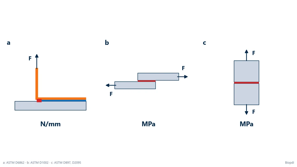
The table summarizes the differences:
| Test | Where the load acts | Result | Standards |
|---|---|---|---|
| Peel | line at the separation front | average force / width, N/mm | D903, D1876, D3330, D6862, ISO 11339 |
| Lap shear | overlap area, in the plane of the adhesive | maximum force / area, MPa | ASTM D1002 (metal), D3163 (plastic) |
| Butt tension | entire area, normal to the adhesive | maximum force / area, MPa | ASTM D897, D2095 |
| Pull-off (coatings) | dolly area, normal to the coating | maximum force / area, MPa | ISO 4624:2023, ASTM D4541 |
The study by Pedroso et al. (2026) shows the contrast in numbers. Among the adhesives tested, the polyurethane SikaForce 710 had the highest floating roller peel (up to 5.41 N/mm, ASTM D3167), and the epoxy Araldite AV 138 had the highest butt tensile strength (29.04 MPa, ASTM D2095). The authors attribute the peel result to the ductility of the adhesive, which deforms and dissipates energy at the front, and the tensile result to the intrinsic strength of the material. This is the rule of thumb in bonding: flexible, tough adhesives resist peel better; rigid epoxies resist shear and tension better. That is why bonded joint design avoids loading the adhesive in peel.
A Biopdi calculation with these numbers shows the scale, without comparing the units directly. A 25 mm strip of the polyurethane withstands 5.41 × 25 = 135 N in peel, whatever the bonded length, because only the front is working. A hypothetical area of 25 × 25 mm = 625 mm² of the epoxy would withstand 29.04 × 625 = 18,150 N, about 18.2 kN, in butt tension. The same width of adhesive holds more than a hundred times less when it is peeled than when it is pulled in tension as a whole.
For tapes, "tensile strength" has yet another meaning. In technical data sheets, the tensile strength of a tape is that of the backing (the film, paper or fabric that carries the adhesive), measured on a 1 in strip and expressed in lb/in, as tesa explains; it is the strength of the material, not of the adhesive. Anyone comparing "peel strength" with "tensile strength" on a tape data sheet is comparing adhesion with backing strength. Shear of bonded joints is covered in the shear test article, and pull-off, together with the adhesion of mortars and paints, in the bond test article. Pull-out of anchors and anchor bolts, which also comes up in peel searches, is a different test, explained in pull-out test.
Factors that affect the result and common mistakes
The peel test result depends as much on the test conditions as on the adhesive: speed, angle, dwell time, temperature, substrate, surface preparation and arm thickness all change the number. The main factors:
- Speed: pressure-sensitive adhesives and elastomers are viscoelastic; in general, the faster the test, the higher the force. That is why each standard fixes the speed.
- Dwell time and application pressure: the adhesive of a tape wets the surface gradually, and adhesion increases with contact time and roller pressure.
- Temperature and humidity: near the glass transition of the adhesive, the result changes a lot; that is why conditioning and test temperature go into the report.
- Substrate and preparation: the same tape gives different numbers on stainless steel, glass, polypropylene and ABS, because the surface energy changes. Low surface energy plastics, such as PP and PE, are the hardest to bond.
- Arm thickness and stiffness: they change the energy spent on bending, especially in T-peel with metal arms.
- Adhesive layer thickness: thicker layers dissipate more energy at the front and, up to a point, increase the result.
The mistakes that most distort the result, or the reading of it:
- Using the maximum force as the peel strength, instead of the average over the steady section.
- Setting the window on crosshead displacement without the factor of 2 at 180° and in T-peel.
- Comparing different angles, speeds, widths or dwell times.
- Treating 25 mm as 1 in in conversions (a 1.6% error).
- Reading N/mm as MPa, or comparing peel with shear by the number.
- Citing a withdrawn standard, such as ISO 8510-1 or ISO 11339:2010, or mixing up the parts of ISO 8510 (part 2 is the 180° one).
- Reporting as adhesive strength a test in which the arm tore or stretched.
- Accepting a test specimen that slipped in the grip or peeled at an angle.
- Using an oversized load cell, with readings below 15% of full scale.
- Using peel to size the joint, when the standard states it does not provide design information.
- Confusing terms: cathodic disbondment is a corrosion test; impact peel (ISO 11343) is an impact test with a wedge; pull-off is tension with a dolly; pull-out is an anchorage test. In texts from Portugal and in machine translations, "descolagem" and "descamação" appear for the same peel.
Applications of the peel test
The peel test is the standard quality control for everything that depends on a bonded flexible layer: tapes, labels, packaging, laminates, flexible circuits, wound dressings and coatings. The most common uses:
- Tapes and labels: 180° and 90° adhesion on a standard panel (D3330, ISO 29862, D6252, FINAT), for batch approval and adhesive development.
- Flexible packaging: controlled opening of sealed lids and seal strength (F88), in food and medical products.
- Laminates and multilayer films: T-peel between layers to evaluate the laminating adhesive.
- Electronics: copper adhesion on flexible circuits and laminates (IPC-TM-650 2.4.9).
- Structural adhesives: floating roller and climbing drum (D3167, D1781) on metal and sandwich panels, in the aerospace and automotive industries.
- Medical products: wound dressings, electrodes and skin adhesives, where the force must be high enough to hold and low enough to remove without injury.
- Pipeline coatings: peel of the external pipe coating, with the result in force per width.
- Footwear and textiles: sole bonding and fabric laminates.
For films and packaging, the peel test usually comes together with other tests on the same machine: film tensile testing per ASTM D882 and tear propagation by the tear test.
Peel testing on the Biopdi universal testing machine
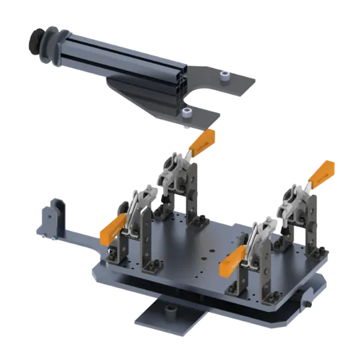
The peel test is performed on a constant-rate universal testing machine, with a low-capacity load cell, a grip for the flexible arm and the fixture for the geometry. The Biopdi universal testing machine lists tape peeling among its tests and has the tape adhesion fixture per ASTM D3330, which replaces the grips. The BioLab software acquires force and position, lets you review the curve point by point and exports the data in CSV, from which the average over the standard's window is calculated. The panel below shows the machine, the role of each part in the peel test and the tape adhesion fixture.
The universal testing machine in the peel test
The M2 line has single-column models, from 200 N to 10 kN, and dual-column models, from 5 kN to 1,000 kN. Each part of the machine has a function in the test:
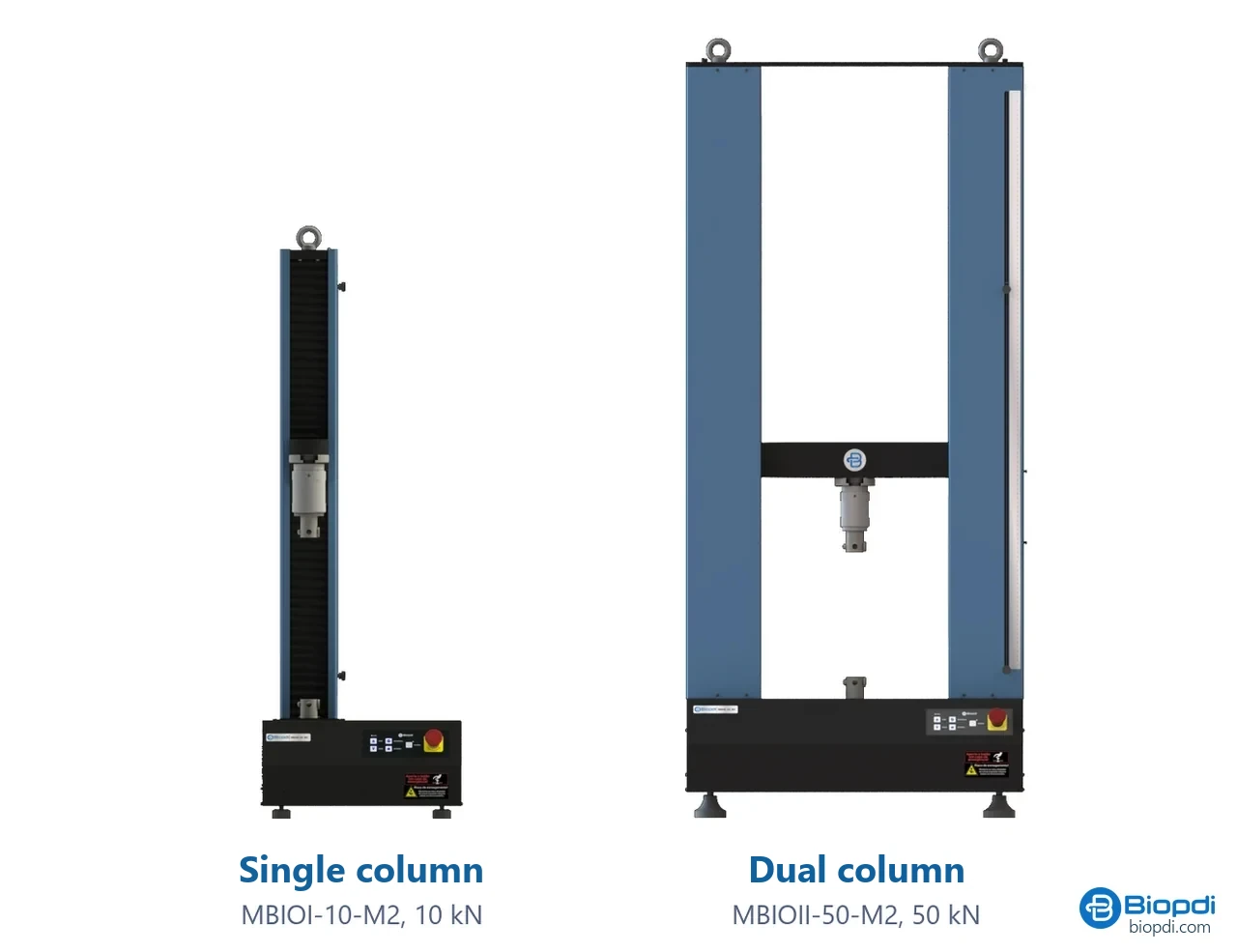
- Moving crosshead peels at the speed of the standard
- Load cell small, for a few newtons
- Fixture tape adhesion or grips
- Displacement from the crosshead, no extensometer
- BioLab software force × displacement curve
- Panel and emergency stop positions and stops the test
Fixture for the peel test
The fixture below is mounted on the same machine, in place of the grips:
The choice of model follows force and speed. Peel forces generally range from fractions of a newton to a few tens of newtons, and the line has load cells starting at 0.05 kN. As for speed, peel standards call for 50.8 mm/min (IPC) up to 300 mm/min (D3330 and FINAT), including the 254 mm/min of D1876; the models in the table cover this range. Since at 180° and in T-peel the crosshead travels twice the peeled length, check the free travel between the grips against the length the standard requires to be peeled. To compare models and configurations, see how to choose a universal testing machine.
| Application | Range | Biopdi model |
|---|---|---|
| Tapes, labels, films, packaging | 200 N to 1 kN; 0.01 to 600 mm/min; 425 mm stroke | MBIOI-1P-M2 portable |
| Adhesives, laminates, T-peel with metal arms | 2 to 10 kN; 0.01 to 500 mm/min; 890 mm stroke | MBIOI-10-M2 |
A 90° table with pulley, floating roller, climbing drum and peel drum are not part of Biopdi's fixture line. Peel is one of the mechanical tests that the same universal testing machine performs.
Other tests and technical references
Tests performed on the Biopdi universal testing machine


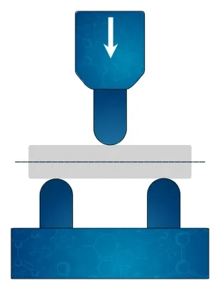

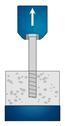


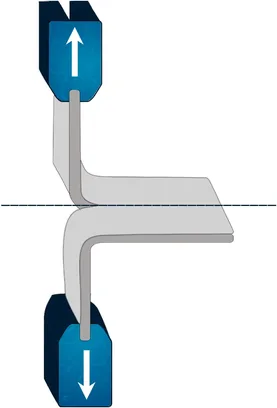
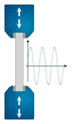




Related technical references
Tear test: tear strength testing, standards and calculation
The tear test measures the force to start or grow a tear in rubber, film, fabric and leather. ASTM D624, ISO 34-1, D1938, D2261 standards and calculation.
Puncture resistance test: standards, methods and calculation
Puncture resistance test: the force and energy for a probe to pierce films, geomembranes, geotextiles and gloves. ASTM, ISO, EN standards and calculation.
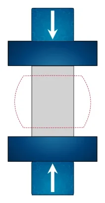
ASTM D695: compression testing of rigid plastics (test specimen, 1.3 mm/min and calculations)
ASTM D695-26 measures compressive strength, yield and modulus of rigid plastics: a 12.7 × 12.7 × 25.4 mm prism at 1.3 mm/min. Calculations and ISO 604.
Frequently asked questions
What does the peel test measure?
It measures the force per unit width needed to progressively separate two bonded materials at a constant angle and speed. The main result is the average force over the steady-state region divided by the width, in N/mm or N/25 mm. The report also gives the initial peak and the failure mode.
What is the formula for peel strength?
P = F̄ / b, which is the average force over the steady-state peel region divided by the specimen width. The initial peak and the final region are left out of the average. Example: an average of 10.0 N on a 25 mm tape gives 0.400 N/mm, or 10.0 N/25 mm.
What are the peel strength units and how do you convert them?
N/mm (the same as kN/m), N/cm, N/25 mm, lbf/in and oz/in. With 1 lbf = 4.4482216 N and 1 in = 25.4 mm: 1 N/mm = 5.710 lbf/in = 91.36 oz/in = 25 N/25 mm; 1 lbf/in = 0.1751 N/mm; 1 oz/in = 0.01095 N/mm. N/25 mm is not the same as N/in. The two differ by 1.6%.
What type of test is ASTM D903?
It is a comparative 180° peel strength test for adhesive bonds, with a flexible adherend bonded to another adherend under standardized conditions of preparation, temperature and speed. The edition current on October 13, 2026 is D903-98, reapproved in 2025.
What is the difference between 90° and 180° peel?
In a 90° peel, the flexible arm leaves the substrate perpendicular to it, and the substrate rides on a sliding table to keep the angle constant. In a 180° peel, the arm is folded back on itself and pulled parallel to the substrate. For the same adhesive, the force at 180° is lower because the energy per unit width equals F/b × (1 − cos θ). Values from the two angles cannot be compared or converted.
Is peel strength the same as shear strength or tensile strength?
No. A peel test concentrates the load along a line and gives force per unit width, in N/mm. Lap shear and butt tensile tests spread the load over the bonded area and give force per unit area, in MPa. A flexible polyurethane can come out on top in peel (5.41 N/mm) while a rigid epoxy leads in tension (29.04 MPa), as Pedroso et al. (2026) showed.
What is the ISO pull-off standard and how does it differ from peel?
The ISO pull-off standard is ISO 4624:2023, for paints and varnishes. A dolly bonded to the coating is pulled off by a perpendicular tensile load, and the result is given in MPa. In a peel test, a flexible adherend is peeled away progressively and the result is given in N/mm. Pull-off and other adhesion tests are covered in the bond test article.
What is the peel wheel test?
It is a 90° peel of a metal foil bonded to a freely rotating drum, so the peel front always stays at the top of the drum. It is the IPC-TM-650 2.4.9 method for copper on flexible dielectrics, with a 6 in reference drum and a speed of 50.8 mm/min. It is not the same as the ASTM D1781 climbing drum test, where the drum winds up the arm and climbs along the panel.
Why is the initial peak discarded?
The peak includes crack initiation and the settling of the arm, so it does not represent steady-state peeling. The standards average over the steady region. ASTM D1876 uses the specified length after the initial peak, and ISO 11339:2022 discards the first and last 25 mm.
Which adhesive is best for bonding flexible PVC to PVC, based on peel testing?
No universal ranking has been published. The result depends on the plasticizer in the PVC, the solvent or adhesive, the surface preparation and the cure time, and values from different data sheets are not comparable. The way to find out is to test the candidates in T-peel (ASTM D1876 or ISO 11339) under the same conditions and compare the average force per unit width and the failure mode. Plasticizer can migrate into the adhesive and reduce adhesion over time, so it is also worth testing after aging.
How is the peel test done on pipeline coatings?
A strip of the pipe's external coating is cut and peeled off at a constant speed, and the result is the force per unit width, in N/mm. The requirements and the test temperature come from the coating standard, such as the ISO 21809 series. This should not be confused with cathodic disbondment, which evaluates the loss of coating adhesion under cathodic protection.
How can peel strength be increased?
Prepare the surface (cleaning, abrasion, primer, or corona and flame treatment on low surface energy plastics), choose a more flexible and tougher adhesive, increase the bond line thickness within the recommended range, and respect the cure or contact time. At the design stage, the best solution is to keep the joint from being loaded in peel and to load it in shear instead.