
A weld test specimen is a machined strip cut from a welded plate or pipe (the test coupon). It is used in destructive testing to prove that a welding procedure or a welder produces a sound, strong joint. For procedure qualification, ASME IX and ISO 15614-1 require 2 transverse tensile tests and 4 bend tests. A bend test fails if an open discontinuity larger than 3 mm appears. It is also called a welding test specimen (in Brazil also "corpo-de-prova", the spelling used in Petrobras standards), or simply a test specimen. The coupon is also called a test plate, test piece or test coupon. Both tests are performed on a universal testing machine (UTM). The tensile test measures the strength of the joint and records where it fractured. The guided bend test bends the strip to about 180° over a former whose diameter is calculated (usually 4 times the thickness) and then examines the face that was in tension.
In short:
- Procedure (WPS and PQR): 2 transverse tensile specimens and 4 bend specimens. In thin plate these are face and root bends; in thick plate they are side bends (ASME BPVC IX-2025, Table QW-451.1; ISO 15614-1:2017, Table 1).
- Welder (WPQ): bend test, fracture test or radiography only. There is no tensile test (ASME IX and ISO 9606-1:2012).
- Tensile test passes when: Rm ≥ the specified minimum tensile strength of the base metal. Under ASME IX, if the specimen breaks in the base metal outside the weld, a result up to 5% below that minimum is accepted (QW-153).
- Bend test passes when: no open discontinuity larger than 3 mm appears on the convex face. Corner cracks do not count unless they come from an internal defect.
- Former: diameter d = 4ts, where ts is the specimen thickness, for a base metal with a minimum elongation A of 20% or more. Below that, d = 100·ts/A − ts (ISO 5173:2023).
This guide is for the lab that runs the tests and for the quality team that reads the report. It covers where the specimens come from, how each one is machined, how the tensile and bend tests are run to standard on the universal testing machine, how results are accepted or rejected, and which mistakes invalidate a result. The basics of the bend test and the tensile test have their own articles. This one focuses on the welded joint.
What a weld test specimen is and what it is for
A weld test specimen is the machined sample that carries a representative slice of the joint into the testing machine: base metal, heat-affected zone (HAZ) and weld metal. It comes from a coupon, which is the test joint welded under controlled conditions, and "test specimen" refers to each strip cut from that coupon. The distinction matters. The coupon is welded by the person or company being qualified, following the WPS for groove preparation, root opening, tack welding and cleaning. The specimen is prepared and tested by the lab. The general concept of a test specimen, with the terms sample, test piece and core, is covered in a separate article.
The coupon serves two different qualifications, and confusing them causes most of the questions people have:
- Procedure qualification: the company writes a welding procedure specification (WPS; EPS in Brazil), welds the coupon to it, and records the parameters and test results in the procedure qualification record (PQR; RQPS in Brazil). This proves that those parameters, with that base metal and that filler metal, produce a joint with the required strength and ductility. That is why both tensile and bend tests are required.
- Welder qualification: the welder welds a coupon following a WPS that is already qualified, and the welder performance qualification record (WPQ; RQS in Brazil) certifies that the welder deposits weld metal without defects. This proves skill, not strength, so the welder does a bend test, fracture test or radiographic test, with no tensile test.
The two destructive tests measure different things on the same joint. The transverse tensile test shows whether the joint is at least as strong as the specified base metal. The bend test shows whether the joint can take large plastic deformation without cracking open, which reveals lack of fusion, slag inclusions, porosity and incomplete penetration. Neither test replaces the other, and both complement the non-destructive tests performed on the coupon before it is cut.
Weld testing standards: qualification and test method
Weld test specimen standards fall into two groups. Qualification standards say how many specimens to take and what result passes. Test method standards say how to machine and test each one. ASME BPVC Section IX and AWS D1.1 cover both in the same document. In the ISO family they are separate: ISO 15614-1 (procedure) and ISO 9606-1 (welder) call for the tensile test to ISO 4136 and the bend test to ISO 5173. That is why ISO 5173 does not pass or fail anything. It describes the test and leaves acceptance to the application standard.
The table summarizes the role of each standard, with editions checked on October 2, 2026:
| Standard | Role | What it defines for the specimen | Edition |
|---|---|---|---|
| ASME BPVC Section IX | procedure and welder qualification (pressure vessels, boilers, piping) | number (QW-451, QW-452), drawings (QW-462), removal (QW-463), test jigs (QW-466), acceptance (QW-153 and QW-163) | 2025 |
| AWS D1.1/D1.1M | structural welding of steel | number, tensile specimens, bend jigs and acceptance | 2025 |
| ISO 15614-1 | procedure qualification (steel, nickel) | 2 tensile and 4 bend tests, removal, acceptance | 2017 + Amd 1:2019 |
| ISO 9606-1 | welder qualification (steel) | bend or fracture test, acceptance, validity | 2012, confirmed in 2023 |
| ISO 4136 | method: transverse tensile test | dimensions, extraction, machining, report | 2022 |
| ISO 5173 | method: bend test | thickness, width, former, rollers, angle, report | 2023 |
In Brazil, clients usually refer to one of these codes: pressure vessel and piping projects follow ASME IX, steel structures follow AWS D1.1, and European suppliers bring the ISO family. Petrobras contracts have a corporate welding standard (N-133) that refers to the codes, so the applicable clause must be read in the contract documents. In Portuguese, the terms EPS, RQPS and RQS are the usual translation of WPS, PQR and WPQ.
How many specimens and where to remove them
The number of specimens for a procedure qualification is fixed in both families of standards: 2 transverse tensile specimens and 4 transverse bend specimens for a full-penetration butt joint. What changes with thickness is the type of bend. In thin plate, 2 face bends and 2 root bends are tested. In thick plate, side bends become allowed or mandatory, because bending a 25 mm thick strip over its face would need a huge former and force, and would only examine the surface.
The diagram below compares where each standard makes the switch. In ASME IX, below 10 mm it is 2 face and 2 root bends; from 10 to 19 mm, 4 side bends may replace them; from 19 mm up, 4 side bends are mandatory. In ISO 15614-1, the switch is allowed from 12 mm. In the ISO 9606-1 welder test, when qualification is by bend test only, the minimum is 2 root and 2 face bends below 12 mm and 4 side bends from 12 mm up.
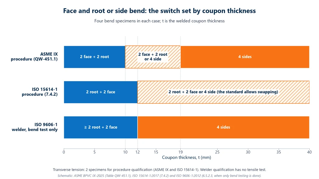
The table lists the destructive tests required in each case. ISO 15614-1 has two examination levels. At level 1, visual examination, tensile tests and bend tests are enough. At level 2, radiographic or ultrasonic testing, surface crack detection, impact testing when specified, hardness testing and macro examination are added.
| Qualification | Transverse tensile | Bend | Source |
|---|---|---|---|
| Procedure, ASME IX | 2 | 4 (2 face + 2 root, or 4 side) | QW-451.1 |
| Procedure, ISO 15614-1 | 2 | 4 (2 root + 2 face, or 4 side) | Tables 1 and 2; 7.4.2 |
| Welder, ASME IX | no | 2 (face and root, or side), or radiography | QW-452.1 |
| Welder, ISO 9606-1 | no | bend test only: ≥ 4; with radiography: 2 additional for some processes | Table 13; 6.5.2 |
The removal position is also specified. ISO 15614-1 requires a plate coupon at least 350 mm long, with each plate at least 150 mm wide, and 25 mm discarded at each end, because the start and end of the weld bead have different thermal conditions from the rest. Between the discards there are two zones, each with 1 tensile specimen and bend specimens, one zone for impact testing and another for macro examination and hardness. ASME IX shows the positions in Figures QW-463.1, with separate figures for coupons below 19 mm and from 19 mm up. In the ISO 9606-1 welder test, at least one specimen must include a stop and restart of the weld bead, and the welder may not grind the root or the face before testing.
The photo shows the welded coupon and the specimens cut from it: two tensile specimens, with the weld in the middle of the gauge length, and bend strips that are still straight. In the background is the universal testing machine with the mandrel-and-roller bend fixture where they will be bent.
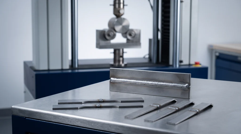
Each specimen is marked with the position it came from in the coupon, and cutting must not alter the material. ISO 4136 prohibits shearing steel thicker than 8 mm, and thermal cuts must stay at least 8 mm from the final surface of the gauge length. For other metals, only machining is allowed. ISO 5173 requires all material affected by thermal cutting or shearing to be removed mechanically. Under ISO 15614-1, the non-destructive tests on the coupon are done and passed before cutting, and it is acceptable to take the specimens from areas free of the imperfections that NDT found within the acceptance limits.
Transverse tensile test of the welded test specimen
The transverse tensile test applies an increasing, continuous force to a test specimen cut across the weld until fracture, to determine the tensile strength of the joint and the location of the fracture (ISO 4136:2022). The weld axis sits in the middle of the parallel length, so that the weld metal, both heat-affected zones (HAZ) and a piece of base metal on each side are loaded in tension together. Because the cross-section is the same along the whole length, fracture occurs in the weakest region of the joint, which is why the fracture location is part of the result.
Dimensions and preparation of the tensile test specimen
Under ISO 4136:2022, the plate specimen for thicknesses above 2 mm has a parallel length 25 mm wide (b0), grip ends 12 mm wider (b1 = b0 + 12), a transition radius of at least 25 mm and a parallel length of at least Ls + 60 mm, where Ls is the width of the weld after machining. The overall length is whatever the machine grips require. For pipe, the width drops to 12 mm for diameters between 50 and 168.3 mm and to 6 mm up to 50 mm, and pipes up to 50 mm may be tested as full sections. The specimen thickness is that of the plate next to the weld; above 30 mm, when the application standard requires the full thickness, it may be divided into several specimens.
The diagram below shows the ISO 4136 plate specimen with these dimensions, using as an example a 12.7 mm plate with a 20 mm wide weld, which calls for a parallel length of at least 80 mm. In the side view, the face and root reinforcement are shown dashed: they are machined off flush with the plate.
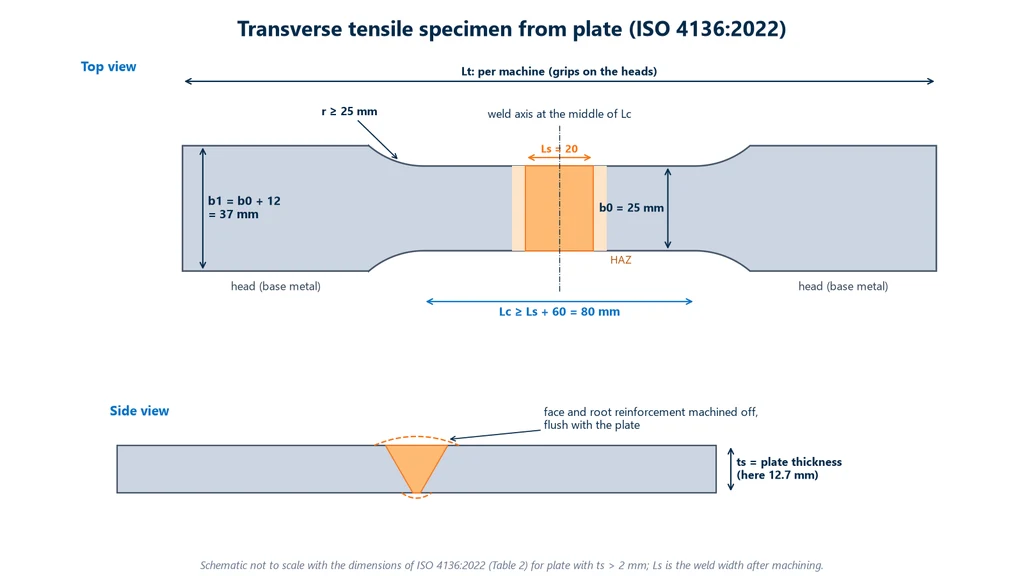
The reinforcement is removed because excess weld metal increases the cross-section at the weld and shifts the fracture away from it: the test would then measure the base metal and hide a weak weld. ISO 4136 requires all excess weld metal to be removed, unless the application standard states otherwise, and leaves undercut in place, because it is a joint defect the test must detect. ISO 15614-1 adds that, for pipe up to 50 mm tested as a full section, the internal reinforcement may remain. In ASME IX, Figure QW-462.1(a) calls for the reinforcement to be "approximately flush" with the base metal, removing the minimum amount of material, with a nominal width of 19 mm (3/4 in) in the reduced section, a parallel length equal to the weld width plus 13 mm and a transition radius of at least 25 mm. Up to 25 mm thick, ASME requires one full-thickness specimen; above that, it allows the thickness to be divided into strips that together count as one test (QW-151.1).
Test procedure and strength calculation
The load is applied gradually and continuously, following the principles of ISO 6892-1 for metals at room temperature (ABNT NBR ISO 6892-1:2024 in Brazil), between 10 and 35 °C. In qualification, usually only the maximum force and the fracture location are determined; in these cases ISO 4136 accepts any of the ISO 6892-1 speed control options. The tensile strength is the maximum force divided by the original area measured before the test:
Rm = Fm / S0, with Fm in N, S0 = measured width × thickness, in mm², and Rm in MPa.
ASME says the same in different words: the ultimate total load divided by the least cross-sectional area, calculated from actual measurements made before loading (QW-152). After fracture, ISO 4136 requires the fracture surfaces to be examined, the type, size and number of imperfections that may have affected the result to be recorded, and the location where the specimen fractured to be noted; a light macro etch on the side helps locate the fusion line. The curve and the concept of ultimate tensile strength are covered in a separate article, and tensile testing of metals in general in the guide to ASTM E8 and ISO 6892-1.
Tensile acceptance criteria
The criterion in qualification standards compares the joint strength with the specified minimum strength of the base metal, not with the actual strength of the plate used in the coupon:
- ASME IX (QW-153.1): Rm not less than the specified minimum of the base metal, or of the weaker of the two in dissimilar joints, or of the weld metal when the construction code allows a lower-strength filler metal. If the specimen breaks in the base metal, outside the weld and the fusion line, it is accepted with a strength up to 5% below the specified minimum.
- ISO 15614-1 (7.4.1): Rm not less than the specified minimum of the base metal, unless another requirement is defined before testing; in dissimilar joints, that of the lower-strength metal. The standard has no 5% tolerance.
- AWS D1.1: strength not less than the minimum of the specified range of the base metal, without the ASME 5% tolerance; the clause should be checked in the contracted edition.
Elongation and yield strength are not part of the acceptance of the transverse joint, because the gauge length mixes base metal, HAZ and weld, which have different properties. When the application standard requires the properties of the deposited metal, the test is a different one: a longitudinal tensile test of a cylindrical specimen machined entirely from weld metal, per ISO 5178:2019.
Bend test of the welded test specimen
The weld bend test plastically deforms the test specimen, without reversing the direction of loading, until one of the surfaces or sections of the joint is in tension, to reveal imperfections on that surface and assess ductility (ISO 5173:2023). It is qualitative: the result is not the force, but the examination of the convex face after bending. The severity of the bend, the formula for strain in the outer fiber and the general types of bend test are covered in the article on bend testing; here we cover the preparation and execution of the welded specimen.
Face, root and side bends: what each one reveals
The bend type is defined by the surface on the outside of the bend, the one in tension. In the face bend, it is the weld face, the side with the wider bead; it reveals defects in the final passes and in fusion with the groove near the surface. In the root bend, it is the opposite side; it reveals incomplete penetration and root pass defects. In the side bend, it is a cross-section of the joint, cut through the full thickness; it shows all passes at once and is the most sensitive to lack of fusion at the groove wall. There are also longitudinal bends, with the weld running along the specimen, used when base metal and weld metal, or the two base metals, have very different ductilities (ASME QW-161.5; ISO 15614-1, 7.4.2).
Thickness, width and edges of the bend test specimen
Under ISO 5173:2023, in transverse face and root bends the specimen thickness is that of the plate, up to 30 mm; above 10 mm, it may be reduced by machining one side only down to (10 ± 0.5) mm, preserving the surface that will be in tension. For plate, the width is at least 4 times the specimen thickness. In the side bend, the width is the plate thickness itself and the specimen thickness is (10 ± 0.5) mm; above 40 mm of plate, the width may be divided into more than one specimen. The edges of the tension face are rounded with a radius of no more than 0.2 ts, limited to 3 mm, with no transverse scratches. All excess weld metal is removed, and undercut remains unless the application standard requires its removal. In ASME IX, the side bend specimen is also 10 mm (3/8 in) thick (Figure QW-462.2).
Former, rollers and angle
ISO 5173 accepts three arrangements: a former pushing the specimen between two parallel rollers or into a U-shaped die (three-point bending); wrap-around bending, with one end clamped and an outer roller rotating 180° around the former; and bending with a backing plate under the specimen. The last two are recommended when base metal, HAZ and weld behave very differently in bending, because the former would concentrate the strain in the softest region and break the specimen without any weld defect. ASME has the same three fixtures in Figures QW-466.1 (plunger and die), QW-466.2 (rollers) and QW-466.3 (wrap-around), and AWS D1.1:2025 in Figures 6.11 to 6.13.
The former diameter, d, is derived from the minimum elongation after fracture, A, required by the base metal specification (ISO 5173:2023, 7.3.1):
- Steel, nickel and nickel alloys with A ≥ 20%: d = 4 ts.
- With A < 20%: d = 100·ts/A − ts, unless the application standard gives another rule; for dissimilar metals, the lower A is used.
- Aluminum and its alloys with A > 5%: the same formula; with A ≤ 5%, the specimen is annealed first, and A is that of the annealed condition.
The formula imposes on the outer fiber a strain equal to the minimum elongation of the material: with d = 4ts, the tension face stretches about 20%. The rollers are spaced at a distance l between d + 2ts + 1 and d + 3.5ts, have a radius of at least 20 mm, and the specimen is at least l + 2R long. In ASME IX, the plunger radius comes from a table by P-Number, the code's grouping of base metals, in Figure QW-466.1; for P-No. 1 carbon steel with a 10 mm specimen, the 38 mm (1-1/2 in) plunger also corresponds to 4 times the thickness.
The diagram below shows the setup of an ISO 5173 face bend with a 10 mm specimen in steel with A ≥ 20%: a 40 mm former on the weld axis, rollers with a minimum radius of 20 mm spaced between 61 and 75 mm, and the tension face at the bottom. On the right, the chart shows how the former grows when the minimum elongation of the base metal falls below 20%: at 10%, it is already 9 times the thickness.
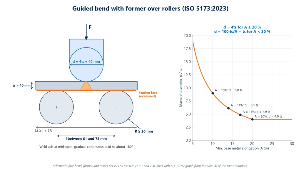
The weld axis sits in the middle of the span, and the load is applied at mid-span, gradually and continuously, perpendicular to the surface. When the application standard does not set another angle, the test ends at about 180°: in the roller arrangement, when the former axis passes the roller axes; in the U-shaped die, when a 3 mm wire can no longer be inserted between the specimen and the die; in wrap-around bending, when the outer roller has rotated 180°. ASME uses the same limits (QW-162.1) and requires the weld and both HAZs to be entirely within the bent portion; if the weld is too wide for this, several specimens across the joint are used. ISO 5173 does not set a speed: it recommends that it be constant and recorded when known.
Bend acceptance criteria
After bending, the outer surface and sides of the specimen are examined, each open discontinuity is measured in any direction, and its location is noted: weld, HAZ or corner. The table compares the criteria of the qualification standards; ISO 5173 has no criterion of its own.
| Standard | Individual discontinuity | Corners | Sum |
|---|---|---|---|
| ASME IX, QW-163 | no open discontinuity > 3 mm in the weld or HAZ | not counted, unless they result from lack of fusion, slag or another internal discontinuity | no sum limit |
| ISO 15614-1, 7.4.2 | no imperfection > 3 mm | disregarded | no sum limit |
| ISO 9606-1, clause 7 | no discontinuity > 3 mm | disregarded, unless there is evidence of incomplete penetration, slag or another discontinuity | sum of the larger ones, between 1 and 3 mm, ≤ 10 mm per specimen |
| AWS D1.1 | none > 3 mm | up to 6 mm, unless originating from slag or lack of fusion (then 3 mm) | indications of 1 to 3 mm totaling ≤ 10 mm |
ASME IX has one more rule: material with elongation below 3% is not bend tested; instead, one macro specimen is taken for each bend position (QW-161). In ISO 15614-1, if a specimen fails, 2 more may be taken from the same coupon for each one that failed, as close as possible to the original position; if either of them fails, the procedure fails.
How to standardize the test on the universal testing machine
Standardizing the test of the welded specimen means making two laboratories, or two operators, reach the same result with the same coupon. On the universal testing machine, this depends less on the machine than on the sequence: identify, measure, choose the fixtures by calculation, align, test with fixed parameters and report everything the standard requires. The procedure below applies to both the tensile and the bend test:
- Identify and trace: coupon number, extraction position, specimen type (tensile, face, root or side), application standard, WPS and base metal. ISO 4136 and ISO 5173 require the position of each specimen in the coupon to be marked.
- Measure before testing: actual width and thickness of the test section, with a caliper or micrometer, at more than one point; ASME uses the smallest measured cross-section.
- Choose the fixtures by calculation: for the tensile test, flat-specimen grips with a capacity above the expected force (exercise 1); for the bend test, the former calculated with the formula, never whichever one happens to be mounted, and a roller spacing within the ISO 5173 range or the die from the ASME or AWS figure.
- Align: for the tensile test, the specimen centered and on the grip axis, with no bending; for the bend test, the weld axis exactly under the former and the rollers symmetrical. A light etch on the face to be put in tension shows the fusion line and helps with centering (ISO 5173, 7.1).
- Fix the parameters in the software test method: constant crosshead speed, force unit in N or kN, end of test at fracture for the tensile test and at a travel equivalent to about 180° for the bend test. The angle can be calculated from the former displacement (ISO 5173, 7.5, referring to ISO 7438).
- Record the curve: force × displacement in both tests. In the tensile test, it gives Fm; in the bend test, it does not decide acceptance, but it documents the execution and shows a sudden drop if the specimen breaks before reaching the angle.
- Examine and measure: fracture location and fracture surface in the tensile test; convex face and sides in the bend test, measuring each open indication.
- Report: under ISO 5173, the report includes the standard, the specimen identification and dimensions, the bend type, the method (former or roller), the former diameter, the roller spacing and radius, the temperature, the type and size of imperfections, the angle, the speed when known, the application standard, deviations, unusual features, date and result. Under ISO 4136, the fracture location and the imperfections on the fracture surface are also included.
The force measurement of the machine must be verified, because the tensile criterion is a number: ISO 7500-1 (ABNT NBR ISO 7500-1:2023 in Brazil) classifies the force-measuring system, and class 1 is the usual one for testing metals. Periodic calibration, performed by an accredited laboratory, is part of the quality system of whoever issues the test report. What the load cell measures and how the class is determined are covered in a separate article.
What the welder needs to know about the test
The welder qualification test is the same bend test described above, applied to a coupon the welder has welded. For the person being tested, the rules that matter are the ones on preparation and acceptance. Under ISO 9606-1:2012:
- What is tested: visual examination is mandatory. It is followed by a bend test, a fracture test (ISO 9017) or radiography. When qualification uses radiography with processes 131 (MIG with solid wire), 135 (MAG with solid wire), 138 (MAG with metal-cored wire) and 311 (oxyacetylene welding), 2 additional bend or fracture tests are also required.
- What you cannot do: grind the root or the face of the weld. The stops and restarts of the root pass and the cap pass are marked before testing, and at least one test specimen is taken from one of them.
- What fails: in the bend test, a discontinuity larger than 3 mm, or a sum of the largest discontinuities between 1 and 3 mm above 10 mm in one test specimen. In the visual examination, an imperfection outside quality level B of ISO 5817 (the standard for imperfection quality levels in welded joints), or level C for some imperfections, such as excess weld metal and undercut.
- If you fail: the welder may repeat the test once without further training.
- The test position: the coupon is welded in the position to be qualified, such as flat, vertical or overhead. The most demanding is usually the fixed pipe inclined at 45° (6G in ASME, H-L045 in ISO), and for that reason it covers more positions.
- What the certificate covers: a thickness range that depends on the coupon (from 3 mm up to twice the deposited thickness, for a coupon between 3 and 12 mm) and the positions and processes tested. Validity is confirmed every 6 months by the welding coordinator, and revalidation can be done by a new test every 3 years, by testing two production welds every 2 years or by documented continuous maintenance.
Under ASME IX, the welder can also be qualified by radiography or ultrasonic testing instead of bend tests, except for some processes, such as short-circuit MIG/MAG, which requires bend tests. The certificate is issued by the inspector or the examining body named in the standard, based on the laboratory test report.
How to interpret the result
The questions below are the ones that come up most often among those who run the tests and those who approve qualifications, and nearly all of them come from applying the rule of one standard to a test performed under another.
The test specimen broke in the base metal below the minimum. Does it fail?
It depends on the standard. Under ASME IX, if the fracture occurred in the base metal, outside the weld and the fusion line, the result is accepted down to 5% below the specified minimum; with a 485 MPa minimum, that gives 460.75 MPa. ISO 15614-1 has no such tolerance: below the minimum, it fails. The reasoning behind ASME is that a fracture away from the weld shows the joint is not the weak point.
It broke in the weld, but above the minimum. Does it pass?
Yes, under all three qualification standards: the criterion is strength, and the fracture location is recorded. The location, however, is engineering information: a joint that consistently breaks in the weld has little margin, and the report should state where it broke and whether the fracture surface showed porosity, slag or lack of fusion.
Does a 5 mm crack at the corner of the test specimen fail it?
Generally not. ASME IX, ISO 15614-1 and ISO 9606-1 disregard corner cracks, except, in ASME and ISO 9606-1, when there is evidence that they resulted from lack of fusion, slag or another internal discontinuity; in AWS D1.1, the corner limit is 6 mm. That is why rounded edges free of scratches are mandatory: a sharp edge opens a corner crack that has nothing to do with the weld and forces a discussion of its origin.
The test specimen broke before reaching 180°. What now?
An open fracture on the tension side is a discontinuity larger than 3 mm and fails the specimen. Before concluding, however, check the test: a former smaller than the calculated one, a weld off the center of the span, reinforcement not removed, or a joint between very dissimilar metals bent with a former instead of a wraparound bend can all break a sound weld. If the cause lies in the test, it is repeated; if it lies in the weld, ISO 15614-1 allows 2 test specimens to be taken for each one that failed.
Which base metal elongation goes into the former formula?
The minimum elongation required by the base metal specification, not the value measured on the plate certificate. When the specification gives two values, for different gauge lengths, the laboratory must record which one it used: ASTM A516 Grade 70, for example, has 21% in 50 mm and 17% in 200 mm, which gives 4ts in one case and 4.9ts in the other. ASME resolves this differently, with the plunger table by P-Number in Figure QW-466.1.
Can I use the elongation from the transverse tensile test as a property of the joint?
No. The gauge length spans base metal, HAZ and weld, and strain concentrates in the softest region; the number depends on the width of the weld and the position of the extensometer. That is why ISO 4136 only recommends measuring elongation when the application standard requires it, with the extensometer positioned for the intended purpose, and the qualification standards accept the joint on Rm and fracture location alone.
Worked examples
The examples use ASTM A516 Grade 70 steel, common in pressure vessels and classified as P-No. 1 in ASME, with a specified tensile strength of 485 to 620 MPa, minimum yield strength of 260 MPa and minimum elongation of 21% in 50 mm and 17% in 200 mm.
1. Force in the transverse tensile test and machine capacity. A 12.7 mm coupon in A516 Gr 70. Under ISO 4136, the width is 25 mm: S0 = 25 × 12.7 = 317.5 mm². The joint must exceed 485 × 317.5 = 153,988 N, or 154.0 kN, and if the plate is at the top of the range it breaks near 620 × 317.5 = 196,850 N, or 196.9 kN. A 200 kN machine would be at 98% of capacity, with no margin: the test calls for the 300 kN one. Under ASME IX, with a 19 mm width: S0 = 19 × 12.7 = 241.3 mm²; minimum of 485 × 241.3 = 117.0 kN and probable maximum of 620 × 241.3 = 149.6 kN, which fit the 200 kN machine with margin. The same coupon, tested under different standards, changes the machine.
2. The error of converting kgf with g = 10. An old report gives 11,200 kgf for a 19.1 × 12.5 mm ASME test specimen, broken in the base metal, in A516 Gr 70. The area is S0 = 238.75 mm². With the conventional value, 1 kgf = 9.80665 N: F = 109,834 N and Rm = 109,834 / 238.75 = 460.0 MPa, below the minimum of 0.95 × 485 = 460.75 MPa: fail. With the rounding 1 kgf = 10 N: F = 112,000 N and Rm = 469.1 MPa, pass. The 2% difference between the two factors is of the same order as the 5% ASME margin. The solution is to set the software to N or kN and record the unit in the report.
3. Former and rollers under ISO 5173. A 10 mm side bend specimen. With A = 22%: d = 4 × 10 = 40 mm; l between 40 + 20 + 1 = 61 mm and 40 + 35 = 75 mm; with 20 mm radius rollers and l = 75 mm, Lt ≥ 75 + 40 = 115 mm. With A516 Gr 70 taken at 17% in 200 mm: d = 100 × 10 / 17 − 10 = 48.8 mm (check: 10 / 58.8 = 17.0% at the outer fiber); l between 48.8 + 21 = 69.8 mm and 48.8 + 35 = 83.8 mm. In practice, the available former immediately above the calculated one is used, never below, because a smaller former makes the test more severe.
4. Estimated force in the bend test. The bend force is not an acceptance criterion, but it determines the fixture and the machine. An engineering estimate treats the test specimen as a fully plastic beam in three-point bending: F ≈ σ·b·ts² / l, with σ between yield strength and tensile strength. For the side bend specimen in example 3, with b = 12.7 mm, ts = 10 mm and l = 70 mm: F ≈ σ × 18.1, that is, from 4.7 kN (σ = 260 MPa) to 8.8 kN (σ = 485 MPa). For a face bend with ts = 10 mm and b = 40 mm, over the same span: from 14.9 to 27.7 kN. Work hardening, friction on the rollers and the change in geometry raise the actual force, so capacity is chosen with margin: the 50 kN range covers these test specimens.
5. Number of specimens and machine for a thick coupon. Procedure qualification under ASME IX on a 25 mm coupon in A516 Gr 70. Since t ≥ 19 mm, 2 tensile tests and 4 side bends are required. Up to and including 25 mm, the tensile specimen is full thickness: S0 = 19 × 25 = 475 mm², with a minimum of 485 × 475 = 230.4 kN and a probable maximum of 620 × 475 = 294.5 kN. The 300 kN machine meets the minimum, but reaches 98% of capacity if the plate is at the top of the range; beyond that, only the 600 kN machine provides margin. For a 30 mm coupon, ASME would allow the thickness to be split into strips (QW-151.1).
Common mistakes in weld test specimen testing
- Confusing procedure qualification with welder qualification: the welder does not do a tensile test, and the procedure is not qualified by bend tests alone.
- Using whatever former is mounted: it depends on the thickness and the minimum elongation of the base metal. A former smaller than the calculated one fails a good weld; a larger one passes a bad weld.
- Not removing the reinforcement, or removing too much: with reinforcement, the fracture moves away from the weld; with excessive machining, the thickness no longer represents the joint.
- Weld off the center of the span: ASME requires the entire weld and HAZ to be in the bent portion, and an off-center former concentrates the bend in the base metal.
- Sharp or burred edges: they produce false corner cracks.
- Converting kgf with g = 10: a 2% error that decides a borderline acceptance (example 2).
- Applying the ASME 5% tolerance to a test under ISO 15614-1: ISO does not have it.
- Expecting acceptance criteria from ISO 5173 or ISO 4136: they are test method standards; acceptance is in ISO 15614-1, ISO 9606-1 or the application standard.
- Using a former on a joint between very dissimilar metals: the bend concentrates on the softer side; the recommended methods are the wraparound bend, the support plate or the longitudinal bend test.
- Undersizing the machine: a 25 mm plate of 485 MPa steel requires more than 230 kN in the tensile test (example 5).
- Thermal cutting close to the gauge section: ISO 4136 requires at least 8 mm between the thermal cut and the final surface of the parallel length.
Supplementary qualification tests
Tensile and bend tests are the ones performed on the universal testing machine, but procedure qualification may require others, and the complete test report brings them together. Level 2 of ISO 15614-1 includes macroscopic examination of an etched cross-section, which shows fusion, penetration and pass sequence (ISO 17639); Vickers hardness HV 10 in the weld, the HAZ and the base metal (ISO 9015-1), with limits by steel group; and, for plate from 12 mm with specified toughness, two sets of three Charpy impact test specimens, one in the weld metal and one in the HAZ (ISO 9016), where the average meets the minimum and a single value may fall below it, provided it is not below 70% (7.4.4). Non-destructive tests, such as radiography, ultrasonic testing, liquid penetrant and magnetic particle testing, are performed on the coupon before cutting. The hardness method is covered in hardness testing, and the Charpy method in impact testing.
Machine for weld test specimen testing
Both weld test specimen tests are performed on the same universal testing machine: the tensile test with plate grips, and the bend test with the bend fixture in place of the grips. Biopdi manufactures the M2 line of electromechanical universal testing machines, with a class 1 force measuring system per ISO 7500-1:2023 (ABNT NBR ISO 7500-1 in Brazil), 5, 20 and 200 kN wedge grips, 50 and 200 kN pneumatic wedge grips and a bend fixture compliant with ISO 5173:2023, with formers changed according to the test specimen thickness. The BioLab software plots the force vs. displacement curve in real time, calculates Rm from the measured dimensions, generates reports in PDF, HTML and CSV and keeps a per-user audit trail, which matters to anyone issuing qualification test reports. Biopdi manufactures the equipment; we do not perform tests, qualify welders or issue certificates. The panel below shows the machine, the role of each part in both tests and the fixtures used.
The universal testing machine in weld test specimen testing
The M2 line has single-column models, from 200 N to 10 kN, and dual-column models, from 5 kN to 1,000 kN. Each part of the machine has a role in the tensile and bend testing of the welded joint:

- Moving crosshead pulls to fracture or lowers the former to 180°
- Load cell class 1: gives the maximum force that decides the tensile test
- Wedge grips hold the ends of the plate test specimen
- Bend fixture rollers and a former changed according to thickness
- BioLab software curve, Rm, report and audit trail
- Control panel and emergency stop position and stop the test
Fixtures for weld testing
The fixtures below are mounted on the same machine, according to the test specimen and the standard:
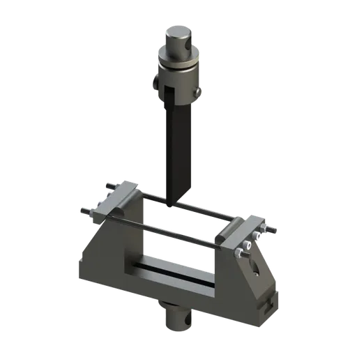
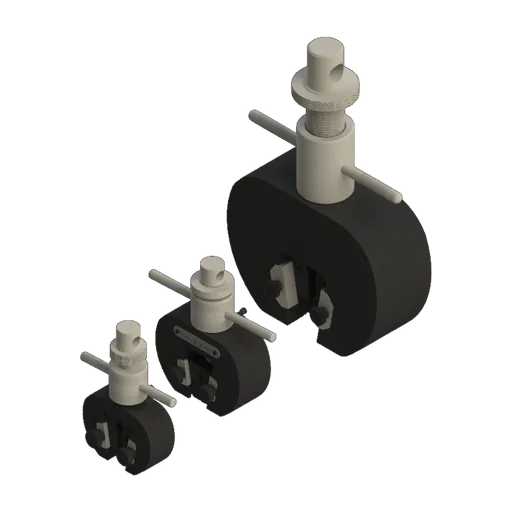
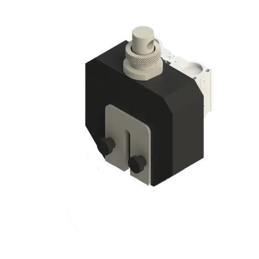
Capacity is chosen based on the tensile test, which is the highest-force test. Thin plate test specimens and 10 mm bend specimens fit the 5 to 50 kN machine (MBIOII-50-M2), suited to welded joints and plates; the ASME tensile test on the 12.7 mm plate in example 1 calls for the 100 to 200 kN machine (MBIOII-200-M2); the same plate under ISO 4136, or thicker coupons, call for the 300 kN machine (MBIOII-300-M2) or larger. How the equipment works in general is covered in the article on the universal testing machine, and you can request a quote for the thicknesses and materials of your laboratory.
Standards cited
The table lists the standards cited in this article, with the current edition checked on October 2, 2026 against the ISO catalogs and the texts of the standards; ASME and AWS are given by the 2025 edition of each code.
| Standard | Scope | Edition |
|---|---|---|
| ASME BPVC Section IX | welding, brazing and fusing qualifications | 2025 |
| AWS D1.1/D1.1M | structural welding code, steel | 2025 |
| ISO 15614-1 | welding procedure qualification for arc and gas welding of steels, nickel and nickel alloys | 2017, with Amd 1:2019; revision in progress |
| ISO 9606-1 | welder qualification, steels | 2012, confirmed in 2023; revision in progress |
| ISO 4136 | transverse tensile test of welded joints | 2022 |
| ISO 5173 | bend test of welded joints | 2023 |
| ISO 5178 | longitudinal tensile test of weld metal | 2019 |
| ISO 6892-1 | tensile testing of metals at room temperature | 2019 |
| ABNT NBR ISO 7500-1 | verification of the force-measuring system of the testing machine (Brazilian adoption of ISO 7500-1) | 2023 |
Other tests and technical references
Tests performed on the Biopdi universal testing machine



















Related technical references
ASTM E8 vs ISO 6892-1: tensile testing of metals, differences and requirements (NBR ISO 6892-1 and A370)
ASTM E8/E8M-25 and ISO 6892-1:2019, adopted in Brazil as ABNT NBR ISO 6892-1:2024, cover the same tensile test of metals at room temperature. They differ in the specimen gauge length (4D in E8, 5D in E8M and 5.65√S0 in ISO), in speed control and its tolerance, in symbols, in rounding and in the standards for the machine and the extensometer. For that reason, elongation from one cannot be compared directly with elongation from the other.
ASTM D790: three-point flexural test of plastics (procedures A and B, support span and calculations)
ASTM D790-25 measures the flexural strength and flexural modulus of plastics using a bar on two supports loaded at midspan. The support span is 16 times the thickness. The strain rate is 1%/min (procedure A) or 10%/min (procedure B), and the test runs until the specimen breaks or reaches 5% strain. Covers the crosshead speed R = ZL²/6d, the formulas, the large-deflection correction, a comparison with ISO 178 and D6272, and worked examples.
Axial-torsion test: combined tension and torsion, von Mises and standards
The axial-torsion test applies axial force and torque to the same specimen. See the tube stresses, von Mises, examples, ASTM E2207 and the machine.
Frequently asked questions
What is a weld test specimen?
It is a strip machined from a welded plate or pipe, the test coupon, for destructive testing. It contains base metal, heat-affected zone and weld metal, and it is used to prove that a welding procedure or a welder produces a sound, defect-free joint. The most common types are the transverse tensile specimen and the face, root and side bend specimens.
How many test specimens does a welding procedure qualification test require?
For a full-penetration butt joint, ASME IX and ISO 15614-1 require 2 transverse tensile specimens and 4 bend specimens. At level 2 of ISO 15614-1, non-destructive testing, macro examination, hardness testing and, when specified, impact testing are also required.
What examinations does the welder undergo in the qualification test?
Visual examination followed by bend testing, fracture testing or radiography, depending on the standard and the process. Under ISO 9606-1, when only bend testing is performed, the minimum is 2 root and 2 face bend specimens below 12 mm and 4 side bend specimens from 12 mm up. The welder does not take a tensile test.
How do you get a welder certificate?
By welding a test coupon following a qualified WPS (welding procedure specification), witnessed by an inspector or examining body, and passing the visual examination and the tests required by the standard, usually bend testing or radiography. The certificate is valid for the thickness range, positions and process tested and, under ISO 9606-1, must be confirmed every 6 months.
When should side bends be used instead of face and root bends?
On thick plate. In ASME IX, side bends may replace face and root bends from 10 to 19 mm and are mandatory from 19 mm up. In ISO 15614-1, the substitution is allowed from 12 mm. The side bend shows all the passes at once and is the best at revealing lack of fusion at the groove sidewall.
What is the former diameter for a weld bend test?
For steel with a minimum elongation of 20% or more, 4 times the specimen thickness, per ISO 5173:2023. Below 20%, d = 100·ts/A − ts. In ASME IX, for P-No. 1 carbon steel with a 10 mm specimen, the plunger is 38 mm, also about 4 times the thickness.
What is the purpose of the 180° bend test on a weld?
To impose a large plastic strain on the tension face, about 20% with the 4t former, so that lack of fusion, slag, porosity or incomplete penetration opens up and becomes visible. The test assesses the soundness and ductility of the joint, not its strength.
What is the rejection criterion in the bend test?
An open discontinuity larger than 3 mm in any direction on the convex surface, in the weld or in the heat-affected zone, per ASME IX, ISO 15614-1 and ISO 9606-1. Cracks at the corners are disregarded unless they result from lack of fusion, slag or another internal discontinuity.
When does the tensile test of a welded joint pass?
When the tensile strength is not less than the specified minimum of the base metal. In ASME IX, if the fracture occurs in the base metal outside the weld, up to 5% below the minimum is accepted (QW-153). ISO 15614-1 has no such tolerance.
What is the best test to evaluate a weld?
No single test: each one answers a different question. The transverse tensile test measures the strength of the joint; the bend test reveals lack of fusion, slag and porosity and assesses ductility; radiography and ultrasonic testing find internal defects without destroying the part; macro examination shows penetration and fusion. That is why qualification standards combine tests, and the weld reinforcement is removed before the tensile and bend tests.
What test speed should be used for weld tests?
For the tensile test, ISO 4136 refers to ISO 6892-1, and any of its control options is acceptable when only the maximum force and the fracture location are measured. For the bend test, ISO 5173:2023 does not set a speed: it requires gradual, continuous loading, preferably constant and recorded in the report.
What machine is needed to test a weld test specimen?
A universal testing machine with plate grips and a bend fixture with formers and rollers, with the capacity set by the tensile test. A 12.7 mm plate of 485 MPa steel requires 117 kN for the 19 mm ASME specimen and 154 kN for the 25 mm ISO specimen, which rules out 50 kN machines for the tensile test.