
The torsion test applies a twisting moment (torque) to a test specimen, usually cylindrical, with one end fixed and the other rotating about the axis, and records the torque and the angle of twist. It gives the shear stress (τ = T·r/J), the shear modulus G, the maximum torque and the angle at fracture, which indicates ductility. The test can run to fracture, to a set number of turns (wires) or to a defined torque. The modulus G is standardized by ASTM E143-20; wires, screws and instruments have their own standards.
Torsion is the loading on shafts, helical springs, screws, drill bits, endodontic files and implants. In this guide you will find the test specimen, the step-by-step test procedure, the formulas with a calculator, how to measure G, the torque-angle curve, why thin-walled tubes are used, how to read the fracture, the test by material and by application, solved exercises, common mistakes, the standards and the machine.
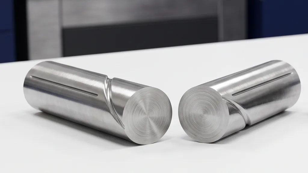
The photo shows a steel bar fractured in torsion. Both halves show a flat fracture surface perpendicular to the axis, typical of a ductile material; the reason for this shape is explained in the section on fracture.
What is the torsion test
Three terms come up all the time in this subject. Torque is the applied load, in N·m. Torsion is the loading or the deformation it causes. Angle of twist is the relative rotation between two cross sections of the part, in radians or degrees. (Testicular torsion and the torsion design of concrete beams are different subjects.)
In the test, one grip is attached to a torque transducer and the other rotates at a controlled speed while the angle is measured. The result is the torque vs. angle of twist curve. In the elastic range it gives the shear modulus G: ASTM E143 defines G as the property used to calculate the compliance of materials in torsion as long as the angle is proportional to the torque, and gives rotating shafts and helical springs as examples.
At the surface of a circular bar in torsion the stress state is pure shear. It is equivalent to a tension and a compression of equal magnitude, at +45° and −45° to the axis. This is what explains the two fracture types shown later. An advantage that is seldom mentioned: a solid bar in torsion does not neck as it does in a tensile test, which is why torsion is used to study large strains and hot forming.
The torque-angle curve gives the mechanical properties of the material in torsion:
- Shear modulus G: the stiffness of the material in shear, taken from the elastic portion.
- Torsional stiffness: the torque required per radian of rotation. It depends on the material (G) and also on the geometry of the part.
- Onset of yielding: the torque at which the curve stops being straight and permanent deformation begins.
- Maximum torque: the highest torque the part withstands before fracture.
- Angle at fracture or number of turns: how much the part rotates before it breaks, the measure of ductility in torsion.
- Absorbed energy: the area under the torque-angle curve, with the angle in radians, gives the energy in joules up to fracture.
These data are used to design shafts and springs, to compare material from different suppliers and batches, and to accept or reject a product, such as a wire or a screw, against the minimum in its standard.
Test specimen for the torsion test
The most common test specimen is a solid cylindrical bar or a tube, always with a circular cross section. The choice is not a matter of convenience: the torsion formulas are valid only for circular sections, in which plane sections remain plane during twisting. Rectangular sections and open profiles warp (Saint-Venant torsion), and the stress in them is not calculated the same way.
- Reduced section: the central portion, of constant diameter, where the material is tested. On it the gauge length L is marked between two sections, where the angle of twist is measured to calculate G.
- Ends: the ends clamped in the machine chucks. The transition from the ends to the reduced section must be smooth, so that stress does not concentrate there and move the fracture outside the measured length.
- Marks: a straight line drawn along the surface before the test becomes a helix during torsion. The slope of this line is the shear strain itself, and marks at both ends of the gauge length allow the angle to be measured without the slack of the grips.
Dimensions must be measured carefully, at more than one position. The diameter enters the calculation of G to the fourth power and that of stress to the third: a 1% error in diameter becomes about a 4% error in G and 3% in the maximum stress. For a tube, the wall thickness is also measured.
There is not always a machined specimen. Wires, screws, endodontic files and bone screws are tested whole, as products, with the fixturing and acceptance criteria defined by the standard for each one. In that case the result describes how that product behaves, not just the material.
Torsion test step by step
- Prepare and identify the test specimen. The surface of the reduced section must have no notches or scratches, which would initiate fracture prematurely.
- Measure the dimensions. Diameter (and, for a tube, wall thickness) at more than one position, and the gauge length L.
- Mark the gauge length, if the angle is measured between marks, as required for determining G.
- Clamp it in the chucks, aligned. The specimen axis must coincide with the axis of rotation; misalignment adds bending to the test.
- Zero the torque and the angle with the specimen mounted and unloaded.
- Rotate at the specified speed, recording torque and angle continuously. In polymers and in hot tests, speed and temperature change the result and go into the report.
- Stop at the test criterion: fracture, specified number of turns (wires) or defined torque.
- Examine the fracture and calculate G, the maximum torque and the angle at fracture, using the formulas in the next section.
How to calculate torsional stress and angle of twist
For a circular section, a homogeneous material and the elastic range, Coulomb's theory applies: sections remain plane, and stress increases linearly with radius. The shear stress at a point at distance r from the center is τ = T·r/J, where J is the polar moment of inertia of the section, the geometric quantity that expresses how much the section resists torsion. For a solid bar, J = π·d⁴/32; the stress is zero at the center and maximum at the surface, where τmax = 16·T/(π·d³).
The angle of twist between two sections separated by length L is θ = T·L/(G·J): it increases with torque and length and decreases with the stiffness of the material (G) and of the section (J). The shear strain at the surface is γ = r·θ/L. It is purely geometric and therefore remains valid after yielding, unlike the stress formula. In the linear portion, the shear modulus is the ratio between the two, G = τ/γ.
The table summarizes these formulas and adds those for the tube, torsional stiffness and the power transmitted by a shaft:
| Quantity | Formula | Note |
|---|---|---|
| Shear stress at radius r | τ = T·r / J | zero at the center, maximum at the surface |
| Polar moment of inertia, solid | J = π·d⁴ / 32 | d = diameter |
| Polar moment of inertia, tube | J = π·(D⁴ − d⁴) / 32 | D outer, d inner |
| Maximum stress, solid shaft | τmax = 16·T / (π·d³) | at the surface |
| Angle of twist | θ = T·L / (G·J) | θ in radians; L = gauge length |
| Shear strain | γ = r·θ / L | geometric: also valid after yielding |
| Shear modulus | G = τ / γ = T·L / (J·θ) | in the linear portion |
| Thin-walled tube | τ ≈ T / (2·π·r²·t) | r = mean radius; t = wall thickness |
| Torsional stiffness | k = T/θ = G·J / L | N·m/rad |
| Power in a shaft | P = T·ω, with ω = 2π·n / 60 | n in rpm |
The diagram below compares the stress distribution in the two sections: in the solid section it rises in a straight line from the center, where it is zero, to the surface; in the thin-walled tube, all the material is far from the center and the stress barely varies through the thickness.
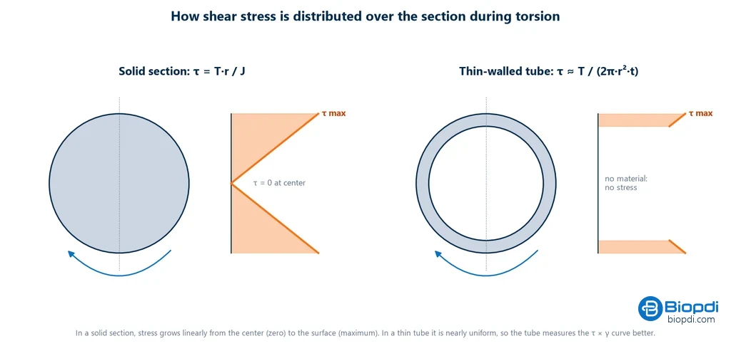
Since the material near the center does very little work, hollow shafts are more efficient: with the same mass, a 50/30 mm tube carries 70% more torque than a 40 mm solid shaft (exercise 4, further on). The calculator below does the math for solid or tubular sections.
Shear modulus G: how to measure it and typical values
The shear modulus (also called the modulus of rigidity or transverse modulus of elasticity) is the ratio of shear stress to shear strain in the elastic range. In the test it comes from the slope of the linear portion of the torque-angle curve: G = (T/θ)·L/J. The standard method is ASTM E143-20, valid where creep is negligible. For an isotropic material, G is related to Young's modulus and Poisson's ratio by E = 2·G·(1 + ν); with ν = 0.30, G ≈ 0.385·E.
The table gives typical values of E, G and ν for metals at room temperature:
| Metal | E (GPa) | G (GPa) | ν |
|---|---|---|---|
| Steel | 207 | 83 (usual range 77 to 83) | 0.30 |
| Aluminum | 69 | 25 (6061-T6: about 26) | 0.33 |
| Copper | 110 | 46 | 0.34 |
| Brass | 97 | 37 | 0.34 |
| Titanium | 107 | 45 | 0.34 |
| Nickel | 207 | 76 | 0.31 |
| Magnesium | 45 | 17 | 0.29 |
Source: Callister and Rethwisch, Table 6.1 (room temperature). For copper and titanium, the tabulated G differs by up to about 11% from the value calculated as E/[2(1+ν)]: textured polycrystalline metals are not perfectly isotropic, and the tables mix alloys. When the design requires precision, G is measured in the test. See also modulus of elasticity.
Torque-angle curve: from elastic behavior to fracture
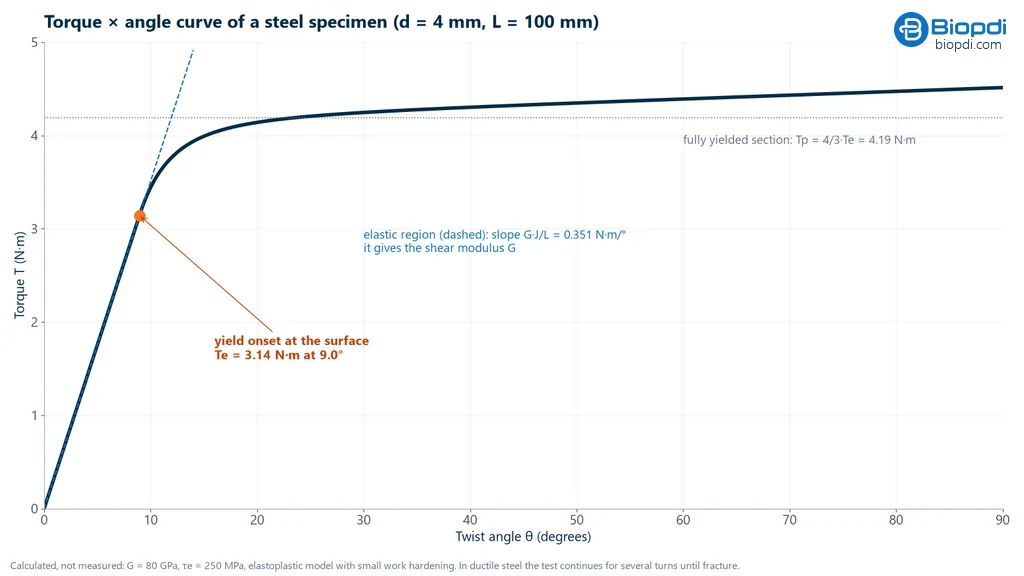
During the test, the machine records torque and angle at every instant and plots the torque-angle curve, from which all the test properties are obtained. The graph below shows the curve of a 4 mm diameter steel specimen: the straight elastic portion, the onset of yielding at 3.14 N·m and the plateau near 4.19 N·m, when the entire section has yielded.
Reading this curve from left to right:
- Elastic portion: torque proportional to angle. The slope equals G·J/L.
- Onset of yielding: it starts at the surface, where τ is maximum, and moves inward. The curve loses linearity gradually, unlike a tensile test, in which the whole section yields at once. This is why care is needed when choosing the portion used to calculate G (it is recommended not to exceed about 75% of the fully plastic torque).
- Fully yielded section: in an elastic-perfectly plastic material, the torque tends to 4/3 of the torque at onset of yielding. In the graph example, from 3.14 to 4.19 N·m.
- Large strains and fracture: in a ductile steel the test continues for several turns. The angle at fracture measures ductility in torsion: ASTM F543 uses it for bone screws, because a larger angle gives the surgeon tactile warning before failure. The area under the whole curve is the energy absorbed up to fracture.
After yielding, the stress is no longer linear with radius and τ = T·r/J no longer applies. Calculating 16·Tmax/(π·d³) at the maximum torque gives the "torsional modulus of rupture", a fictitious value, useful only for comparing identical parts. Nadai's method (1950) obtains the true surface stress from the slope of the curve; at maximum torque it gives τ = 12·Tmax/(π·d³), meaning the elastic formula overestimates by up to about 33%.
Why use a thin-walled tube
In a solid bar the stress varies from zero to τmax, and after yielding the τ-γ curve does not come directly from the test. In a thin-walled tube the stress is nearly uniform through the thickness, and τ-γ is obtained without correction: in a 26/24 mm tube, the difference between the outer and inner fibers is only ±4% (exercise 6). The limitation is that a thin tube can buckle in torsion, whereas a solid bar remains stable up to large strains.
Fracture in the torsion test: ductile and brittle
Because the bar surface is in pure shear, the fracture mode depends on which stress the material withstands least. A ductile material gives way in shear, which is maximum on the transverse and longitudinal planes, and fractures on a smooth plane perpendicular to the axis, as in the opening photo. A brittle material resists shear well and fractures under tension, which is maximum at 45°: the crack follows a helix. The table summarizes both cases:
| Material | Fracture plane | Governing stress |
|---|---|---|
| Ductile (mild steel, aluminum, copper) | transverse, perpendicular to the axis, flat and smooth | maximum shear |
| Brittle (gray cast iron, hardened steel, chalk) | helix at 45° to the axis | maximum tension (σ1 = τ, at 45°) |
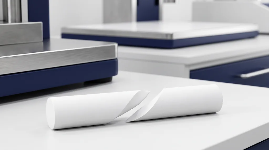
Brittle fracture is easy to demonstrate: twist a piece of chalk with your fingers and it breaks in a spiral. The photo below shows the result, with the fracture surface following a helix at 45° to the axis.
Torsion is also different from the direct shear test. In the direct test, the tooling forces fracture on one plane, with average stress, bending and concentration at the edges. In torsion the shear is pure and the stress state is known.
Torsion test by material and by application
The principle is the same for any material, but what you look for in the curve changes from one material to another.
- Metals: these are the main use. In bars and tubes, the test measures G, yield and maximum torque for the design of shafts and springs; in wires and screws, it is a product acceptance test against a minimum torque or a minimum number of turns.
- Polymers: they are viscoelastic, and their torsional stiffness changes considerably with temperature and with speed. For this reason, the torsion test on plastics usually measures the apparent stiffness over a temperature range, per ASTM D1043, to show where the material stiffens or softens.
- Ceramics and other brittle materials: they fracture along a helix, from tension at 45°, with little or no plastic twist. The strength of ceramics is usually measured by flexural testing, and torsion appears mostly in research.
- Fiber composites: the response depends on the fiber orientation relative to the axis, and the measured G applies only to that orientation.
Several applications have their own standard, with a defined specimen, fixturing and acceptance criterion:
- Wires: twisted at a specified speed; the number of turns to fracture is counted, or a minimum is verified (ASTM A938-18, reapproved in 2024; ISO 7800:2012). ASTM A938 points out that torsion is sensitive to small variations in the material, which makes it useful for assessing wire ductility.
- Small screws: ISO 898-7:1992 determines the breaking torque and the minimum torques of bolts and screws from 1 to 10 mm nominal diameter, property classes 8.8 to 12.9, especially those with a small thread or too short for the tensile test. Breaking torque (test) is not tightening torque (assembly).
- Bone screws: annex A1 of ASTM F543-23 measures torsional yield strength, maximum torque and breaking angle. The standard warns that the method does not predict insertion torque in bone: it serves for product uniformity and comparison between products.
- Endodontic files: ISO 3630-1:2019 specifies torque and angular deflection tests to fracture, with the instrument clamped 3 mm from the tip.
- Shafts and large components: drive shafts and torsion bars require machines of hundreds to thousands of N·m.
Solved torsion problems
Problem 1: maximum stress in a solid shaft. Steel shaft with d = 20 mm and T = 200 N·m.
J = π × 20⁴ / 32 = 15,708 mm⁴. τmax = 200,000 × 10 / 15,708 = 127.3 MPa. Check: 16T/(πd³) = 16 × 200,000 / (π × 8,000) = 127.3 MPa.
Problem 2: angle of twist. The same shaft, with L = 1.0 m and G = 80 GPa.
θ = T·L/(G·J) = 200,000 × 1,000 / (80,000 × 15,708) = 0.159 rad = 9.1°.
Problem 3: G from the test. Steel specimen with d = 4.0 mm and a gauge length of 100 mm. In the linear region, at T = 1.50 N·m, the angle measured between the gauge marks was θ = 4.27° (0.0746 rad).
J = π × 4⁴ / 32 = 25.13 mm⁴. G = T·L/(J·θ) = 1,500 × 100 / (25.13 × 0.0746) = 80,000 MPa = 80.0 GPa. Check: τ = 16T/(πd³) = 119.4 MPa and γ = r·θ/L = 2 × 0.0746 / 100 = 1.49 × 10⁻³; τ/γ = 80 GPa. At 1.5 N·m, the test fits a 5 N·m torque cell.
Problem 4: hollow vs. solid shaft of the same mass. Solid shaft of 40 mm; tube with the same area and D = 50 mm, so dint = √(50² − 40²) = 30 mm.
Solid: J/r = 12,566 mm³. Tube: J = π(50⁴ − 30⁴)/32 = 534,071 mm⁴ and J/r = 21,363 mm³. At the same allowable stress, the tube transmits 1.70 times the torque and has a torsional stiffness 2.13 times higher.
Problem 5: power and shaft diameter. 10 kW motor at 1,750 rpm and τallow = 40 MPa.
ω = 2π × 1,750 / 60 = 183.3 rad/s; T = 10,000 / 183.3 = 54.6 N·m. d³ = 16T/(π·τallow) = 16 × 54,600 / (π × 40) = 6,952 mm³, so d = 19.1 mm. Use 20 mm.
Problem 6: thin-walled tube. 26/24 mm tube (t = 1 mm, mean radius 12.5 mm) with T = 50 N·m.
Approximate: τ = 50,000 / (2π × 12.5² × 1) = 50.9 MPa. Exact: J = π(26⁴ − 24⁴)/32 = 12,292 mm⁴; τ at the outer wall = 52.9 MPa and at the inner wall = 48.8 MPa. The difference is only ±4%.
Common mistakes in torsion testing
- Measuring the angle from the grip rotation. It adds grip slack, chuck deformation and the length outside the gauge section. For G, measure between marks within the gauge length or correct for the system stiffness.
- Misalignment: a specimen axis off the grip line adds bending. ASTM E143 lists concentricity among the critical factors.
- Using τ = T·r/J beyond yield. For the true stress, use Nadai's method.
- Calculating G outside the linear region, which ends gradually.
- Confusing torque with torsion, or tightening torque with breaking torque.
- Applying the circular formula to a non-circular cross section.
- High torque on a thin tube: risk of torsional buckling.
- Ignoring speed in polymers and hot metals, which are sensitive to strain rate.
- Citing the wrong standard: ISO 898-1 is not a torsion standard (the one for small screws is ISO 898-7), and ISO 14801 covers fatigue of dental implants.
- Treating the G table as absolute truth: the value depends on the alloy.
Torsion test standards
There is no general torsion standard for all materials: ASTM E143 covers only the shear modulus, and the other tests are defined by the product standard. The table lists the most widely used:
| Standard | Subject |
|---|---|
| ASTM E143-20 | shear modulus at room temperature |
| ASTM A938-18 (2024) | torsion testing of wire |
| ISO 7800:2012 | simple torsion test of wire |
| ISO 898-7:1992 | torsional test and minimum torques for bolts and screws from 1 to 10 mm |
| ASTM F543-23 | metallic bone screws: torsion, insertion and removal torque, pull-out |
| ISO 3630-1:2019 | endodontic instruments: torque and angular deflection to fracture |
| ASTM D1043 | stiffness of plastics in torsion as a function of temperature |
Torsion testing machine
Every torsion testing machine has the same parts. A rigid frame keeps the two chucks aligned on the same axis. A motor rotates one of the chucks at a controlled speed, while the other stays fixed and is connected to the torque transducer, which measures the torque transmitted by the specimen. An angle sensor measures the rotation, and the software controls the test, plots the torque vs. angle curve and calculates the properties. Torque and angle accuracy, speed range and capacity define which parts the machine is suited for.
The Biopdi torsion testing machine follows this layout, with angle measurement and data acquisition software, and is available in two versions. In addition, Biopdi supplies the axial-torsion universal testing machine, with a torsion module combined with tension, for combined tests (see axial-torsion test); the configuration is defined on request. The photos below show the two versions side by side. On the left, the Complete version, which operates on its own, with a display and keypad console and optional acrylic guard. On the right, the Basic version, which has the motor and the two chucks on a base with a rail and is used together with the universal testing machine.
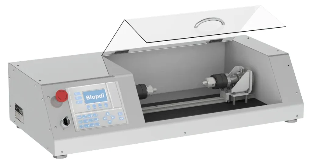
Complete version: stand-alone operation
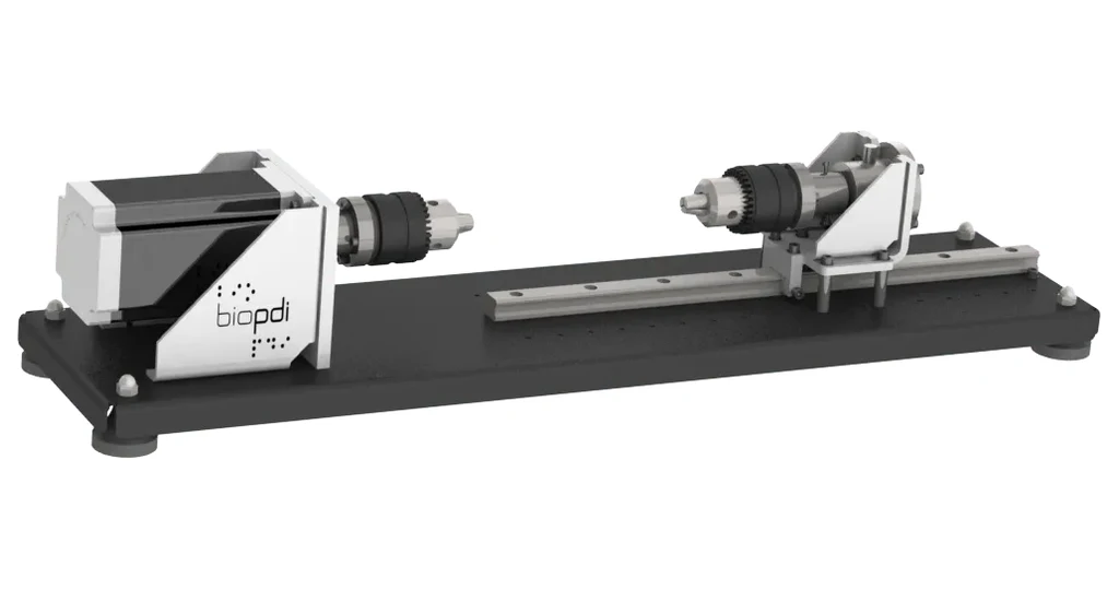
Basic version: used together with the universal testing machine
The table summarizes the characteristics of the two versions:
| Characteristic | Biopdi torsion testing machine |
|---|---|
| Capacities | 1, 5 and 10 N·m (others on request) |
| Speed | 0.01 to 200 rpm |
| Angular accuracy | 0.018° |
| Torque accuracy | 0.005 N·m |
| Specimens | length up to 200 mm; diameters from 1 to 8 and from 5 to 20 mm |
| Dimensions | 600 × 200 × 250 mm (Basic); 900 × 200 × 450 mm (Complete) |
With its range of up to 10 N·m, it is suited for fine wires, small screws, files and dental instruments, implant screws, small metal and polymer specimens and miniature components, such as the 4 mm steel specimen in problem 3. A 20 mm steel shaft already requires about 200 N·m to reach 127 MPa (problem 1): for higher torques, ask about other capacities or our special projects, or request a quote.
The videos show the two versions of the machine in operation.
Other tests and technical references
Tests performed on the Biopdi universal testing machine






Related technical references
Axial-torsion test: combined tension and torsion, von Mises and standards
The axial-torsion test applies axial force and torque to the same specimen. See the tube stresses, von Mises, examples, ASTM E2207 and the machine.
Tensile test: what it is, step by step, calculations and standards (ISO 6892-1)
A tensile test pulls a specimen axially to fracture to measure yield strength, UTS, modulus and elongation. Calculations, steps, standards and specimens.
ASTM D790: three-point flexural test of plastics (procedures A and B, support span and calculations)
ASTM D790-25 measures the flexural strength and flexural modulus of plastics using a bar on two supports loaded at midspan. The support span is 16 times the thickness. The strain rate is 1%/min (procedure A) or 10%/min (procedure B), and the test runs until the specimen breaks or reaches 5% strain. Covers the crosshead speed R = ZL²/6d, the formulas, the large-deflection correction, a comparison with ISO 178 and D6272, and worked examples.
Frequently asked questions
What is a torsion test?
It is a mechanical test that applies torque to a specimen, usually cylindrical, and records the torque and the angle of twist, up to fracture, up to a number of turns or up to a defined torque. It yields the shear modulus G, the maximum torque and the angle at fracture.
What is torsion?
Torsion is the loading of a part by a moment about its longitudinal axis. In a circular cross section, it produces shear stress that goes from zero at the center to a maximum at the surface.
What is the formula for torsion?
The stress is τ = T·r/J; for a solid shaft, τmax = 16·T/(π·d³). The angle of twist is θ = T·L/(G·J), in radians. Both apply to circular cross sections in the elastic range.
What is the shear modulus G?
It is the ratio of shear stress to shear strain in the elastic range, G = τ/γ. It is about 80 GPa for steel and 26 GPa for aluminum, and it is related to Young's modulus by E = 2G(1 + ν).
How is G measured in the torsion test?
From the slope of the linear region of the torque vs. angle curve: G = (T/θ)·L/J, with the angle measured over the gauge length. The standardized method is ASTM E143.
What is the typical fracture of ductile materials in the torsion test?
A plane transverse to the axis, with a flat, smooth surface, because ductile material fails in shear. Brittle materials, such as cast iron and chalk, fracture along a 45° helix, perpendicular to the maximum tensile stress.
What strains does a metal specimen undergo in torsion?
Shear strain γ = r·θ/L, zero at the center and maximum at the surface. The material yields first at the outside and, in a solid bar, there is no necking, which allows large strains before fracture.
Which standards govern the torsion test?
ASTM E143 (modulus G), ASTM A938 and ISO 7800 (wires), ISO 898-7 (bolts and screws from 1 to 10 mm), ASTM F543 (bone screws) and ISO 3630-1 (endodontic files).
What is a torsion testing machine?
It is a machine with one fixed grip connected to a torque transducer and another that rotates at a controlled speed while the angle is measured. The Biopdi machine has capacities of 1, 5 and 10 N·m, speeds from 0.01 to 200 rpm and an angular accuracy of 0.018°.
Can a universal testing machine perform torsion tests?
Yes, in the axial-torsion universal testing machine configuration, with the torsion module combined with tension, which allows combined tension-torsion tests. For pure torsion, the Basic version of the Biopdi torsion testing machine works together with the universal testing machine, and the Complete version operates on its own.
Why are hollow shafts more efficient in torsion?
Because the material near the center does almost no work. With the same mass, a 50/30 mm tube carries about 70% more torque than a 40 mm solid shaft at the same stress.
Why is the stress calculated at fracture not the true stress?
Because after yielding the stress no longer varies linearly with the radius, and 16·Tmax/(π·d³) becomes a fictitious "modulus of rupture", up to about 33% higher than the true value. Nadai's method corrects this using the slope of the torque vs. angle curve.
Interactive simulation
Try the test in your browser and watch the results being calculated.