
Creep is the permanent deformation that increases over time in a material under constant load or stress. In metals, it becomes significant above about 0.4 of the absolute melting temperature, as in boilers and turbines; in lead, plastics and concrete, it already occurs at room temperature. The creep test holds force and temperature constant and records the strain over time, sometimes up to rupture, per ASTM E139 or ISO 204 for metals and ISO 899 for plastics.
It is the test that answers how much a part will deform, or when it will rupture, after years under load: the steam piping of a power plant, the bolt of a hot flange, the plastic water pipe, the concrete beam that keeps sagging months after it is built. In this guide you will find how the test is performed, the creep curve and its three stages, the creep rate and Norton's law, the Larson-Miller parameter, creep of steel and other materials, the difference from stress relaxation and fatigue, worked examples, common mistakes and the standards. In Portuguese, the word for creep ("fluência") also means fluency in a language, which is not the subject here.
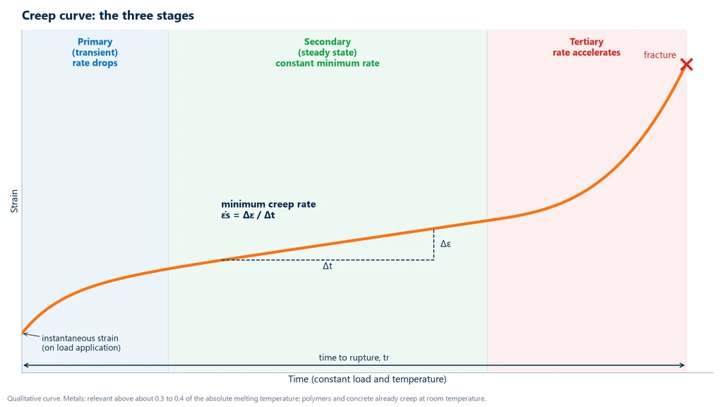
The graph below shows the typical result of a creep test: the strain jumps the moment the load is applied and then keeps growing without any change in load, first more and more slowly, then at an almost constant rate and, near the end, faster and faster until rupture. These three portions are the primary, secondary and tertiary stages, explained in the section on the creep curve.
What the creep test is
ASTM E139-24 defines the test as the determination of strain as a function of time under constant tensile force and constant temperature, and the measurement of the time to rupture. ISO 204:2023 distinguishes four types: the uninterrupted test, with extension measured continuously; the interrupted test, with elongation measured at intervals; the creep rupture test, in which mainly the time to fracture is measured; and the verification test, which confirms a minimum time under a given force.
The difference from the tensile test is time. In a tensile test, the load rises within minutes until fracture. In a creep test, the load stays fixed, often well below the yield strength, and the material deforms slowly, over hours, months or years. That is why a component can fail at a stress it would withstand without any problem in a short-term test.
The result has four main uses: defining the allowable stress of a component for a design life, in hours, at a given temperature; choosing among candidate materials for high-temperature service or sustained load; accepting lots, through the verification test of a minimum time under a given force; and estimating the remaining life of equipment that has been operating for years. In all of them, the test must reproduce the service temperature and stress level, because both greatly change the rate at which the material deforms.
How the creep test is performed: equipment and test specimen
The test depends on three things kept stable for a long time: force, temperature and the measurement of elongation. For metals, the test specimen is mounted with the extensometer, heated in the furnace until the temperature stabilizes, receives the force without shock and stays under it while the elongation is recorded, for hours or thousands of hours, until it reaches the limit strain, the planned time or rupture. For plastics, concrete and other materials that creep at room temperature, the furnace is replaced by a room or chamber with controlled temperature and humidity.
The photo shows a dead-weight creep testing machine: the split tube furnace, open, surrounds the test specimen; the extensometer rods come down from inside the furnace; and the weights hanging at the end of the arm apply the force, multiplied by the lever.
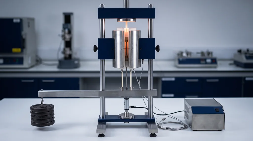
Each part of the equipment is responsible for one of the quantities of the test:
- Load: dead-weight machine with a lever arm, simple and stable for thousands of hours, with several stations; or an electromechanical machine with force control, in which the load cell measures the force at every instant and feeds back the control loop.
- Temperature: three-zone tube furnace, with thermocouples touching the test specimen. A few degrees of variation change the creep rate considerably.
- Strain: high-temperature extensometer, with ceramic rods that come out of the furnace, or non-contact measurement. It is the central measurement of the test: the elongation of the test specimen over time.
- Data acquisition: a computerized system records force, temperature and elongation at regular intervals throughout the test, and the software plots the curve and calculates the rates. In tests lasting thousands of hours, automatic recording is what ensures that no portion of the curve is lost.
The metal test specimen is usually round with threaded ends, with or without shoulders for attaching the extensometer; flat specimens with a pin hole and tube segments are also used, and notched specimens follow ASTM E292. The surface of the gauge section must be free of burrs and scratches, and the dimensions are measured before the test, because the stress is calculated from the initial area. The gauge length, between the marks or between the extensometer contact points, is the base on which the strain is calculated.
Creep curve: the three stages
The creep curve, like the one at the beginning of the article, shows strain over time at constant load and temperature. It begins with an instantaneous strain, almost entirely elastic, at the moment the load is applied, and continues in three stages:
- Primary (transient): the strain rate decreases over time, because work hardening, the hardening of the material by its own deformation, dominates.
- Secondary (steady state): the rate remains approximately constant and minimum, because work hardening and recovery, which softens the material through the rearrangement of dislocations at temperature, balance each other. It is the longest stage and accounts for most of the service life.
- Tertiary: the rate accelerates due to internal damage (cavities at grain boundaries, microcracks) and the reduction of the cross section, until rupture.
From the curve you obtain the minimum creep rate (the slope of the secondary portion), the time to rupture, the elongation and reduction of area at rupture, and the time to reach a limit strain, for example 1 %. To read the minimum rate with less subjectivity, the strain rate is also plotted against time, which shows a clear minimum.
These results define the two properties used in design. Creep strength is the stress that, at a given temperature, produces a specified minimum rate, for example 10⁻⁵ %/h (1 % in 100,000 h), or a specified strain in a given time. Creep rupture strength is the stress that leads to rupture in a given time, for example 100,000 h, at that temperature. The portion that accumulates after loading, the creep strain, is permanent: it does not recover when the load is removed.
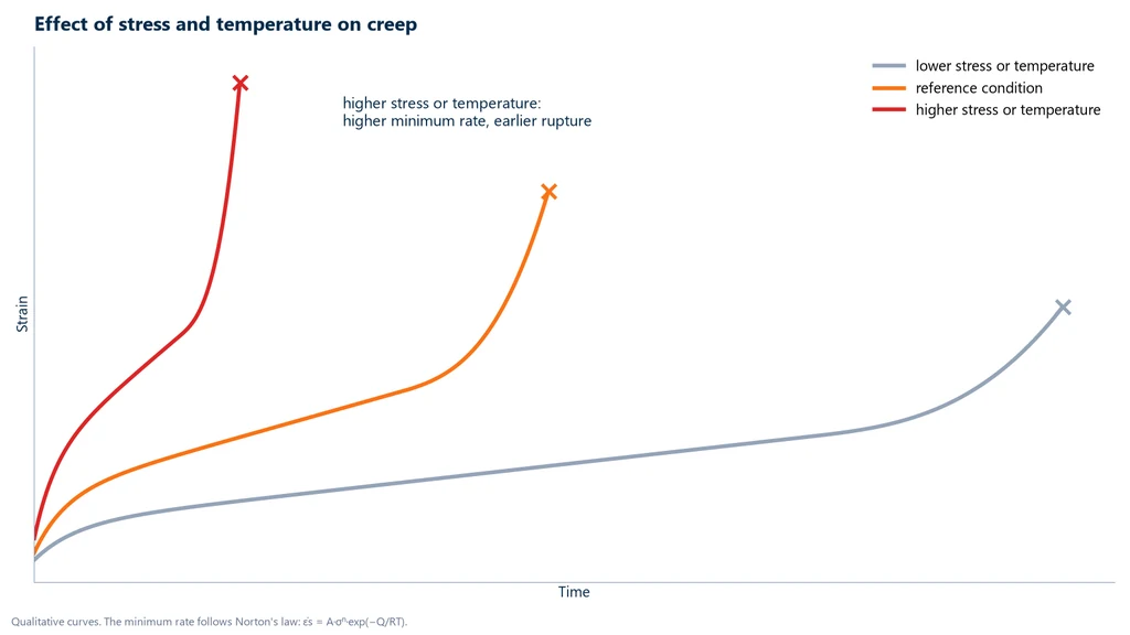
Each curve applies to one stress and one temperature. Increasing either of them raises the instantaneous strain and the minimum rate and shortens the time to rupture; at very high stress and temperature, the secondary stage almost disappears. The graph below compares three conditions: the reference condition, a milder one, in which the material deforms slowly and lasts much longer, and a more severe one, in which it ruptures early.
How to calculate: creep rate, Norton and Larson-Miller
Creep strain is calculated as in the tensile test: the elongation measured by the extensometer divided by the gauge length, ε = ΔL / L0, except that it is now a function of time. The minimum rate, the slope of the secondary portion, is obtained from two points in that portion: the strain increment divided by the time interval between them, in h⁻¹ or %/h.
Norton's law describes how this rate depends on stress and temperature: it increases with stress raised to an exponent n and increases exponentially with temperature, through the Arrhenius term, ε̇s = A·σⁿ·exp(−Q / RT). Two tests at the same temperature and different stresses give the exponent n; two tests at the same stress and different temperatures give the activation energy Q. With both, it is possible to estimate the rate under conditions that were not tested, provided the deformation mechanism is the same.
The exponent n indicates the mechanism, with caution, because the laws are empirical: n close to 1 indicates diffusion creep (Nabarro-Herring through the lattice, Coble along grain boundaries); about 2, grain boundary sliding; from 3 to 6, diffusion-controlled dislocation motion, the most common case in engineering metals; above 10, alloys with precipitates and a threshold stress.
The Larson-Miller parameter combines time and temperature into a single number, LMP = T·(C + log tr). It allows short, hotter tests to be used to estimate the service life, which is longer and cooler: according to the equation, shortening the rupture time by a factor of 10 is equivalent to raising the absolute temperature by about 4 to 5 %. It is the basis of the remaining life assessment of components in creep (API 579-1, Part 10).
The table brings together the formulas of the test. The last two rows, the creep modulus of plastics and the creep coefficient of concrete, are explained in the section on those materials.
| Quantity | Formula | Note |
|---|---|---|
| Creep strain | ε(t) = ΔL(t) / L0 | extensometer elongation over the gauge length |
| Minimum creep rate | ε̇mín = Δε / Δt in the secondary stage | in h⁻¹ or %/h |
| Norton's law with Arrhenius | ε̇s = A·σⁿ·exp(−Q / RT) | n: stress exponent; Q: activation energy; T in kelvin |
| Stress exponent | n = ln(ε̇2 / ε̇1) / ln(σ2 / σ1) | two tests at the same temperature |
| Activation energy | Q = R·ln(ε̇2 / ε̇1) / (1/T1 − 1/T2) | two tests at the same stress; R = 8.314 J/(mol·K) |
| Larson-Miller parameter | LMP = T·(C + log tr) | T in kelvin, tr in hours, C ≈ 20 for low-alloy steels |
| Creep modulus (plastics) | Ec(t) = σ / ε(t) | ISO 899-1 |
| Creep of concrete (simplified) | εcc = φ·εelástica | φ: creep coefficient from NBR 6118 |
Creep of steel
Creep of steel is the slow deformation under sustained load at high temperature. In metals, it becomes important above about 0.4 of the absolute melting temperature, when atomic diffusion becomes fast enough for dislocations to bypass obstacles and for grain boundaries to slide. That is why it governs the design of boilers, steam piping, refinery furnace vessels and tubes, and turbine blades, which operate hot and under constant load for decades.
The onset of creep depends on the alloy: alloying elements such as chromium and molybdenum form carbides and solid solutions that delay this movement. The National Board table (French, 1991) gives the approximate onset temperature for boiler steels:
| Steel | Approximate creep onset temperature |
|---|---|
| Carbon steel | ≈ 427 °C |
| Carbon with ½ Mo | ≈ 454 °C |
| 1¼ Cr-½ Mo | ≈ 510 °C |
| 2¼ Cr-1 Mo | ≈ 538 °C |
| Stainless steel | ≈ 566 °C |
These are approximate values; the current ASME code prevails, and other codes use different criteria (375 °C for ferritic-martensitic steels and 450 °C for austenitic steels in European nuclear standards). For the steam piping of ultra-supercritical power plants, P91 (modified 9Cr-1Mo) is used, whose creep rupture strength at 600 °C is almost twice that of traditional 9Cr-1Mo, with a typical design life of 100,000 hours. A real case: a P91 elbow with incorrect heat treatment, after 20,000 h at about 550 °C, had an estimated remaining life of 53,000 h by Larson-Miller, instead of the 100,000 h of the design (Zhou et al., 2024).
The 0.4 melting temperature rule explains why lead creeps at 20 °C: it melts at 327.5 °C, and room temperature is already almost half of that in kelvin.
Creep in plastics, composites, ceramics, concrete and geosynthetics
The phenomenon is the same in all materials, but the temperature at which it matters, the mechanism and the way it is tested change from one to another.
Plastics. Polymers are viscoelastic: part of the response is elastic, like a spring, and part is viscous, like a fluid that flows slowly. That is why they creep already at room temperature, and the strain depends on time, temperature and humidity. This is what is checked in plastic parts under sustained load, such as automotive brackets and fasteners, medical devices, tanks and pipes. In design, a single modulus of elasticity is not used, but rather the creep modulus, Ec(t) = σ / ε(t), which decreases with loading time. ISO 899-1 (tension) and ISO 899-2 (three-point flexure) give the creep modulus, the strain × time curves and the isochronous stress × strain curves used in design; ASTM D2990 covers tension, compression, flexure and creep rupture. Tests of 1,000 hours are common, with several stations in parallel. For plastic pressure pipes, ISO 9080 extrapolates pressure tests to the 50-year hydrostatic strength.
Composites. In a polymer matrix composite, such as carbon or glass fiber with epoxy resin, the fibers hardly creep and the matrix creeps like a polymer. The result depends on the load direction: in the fiber direction, where the fibers carry most of the force, creep is small; in the transverse direction and in shear, where the matrix does the work, it is much larger. That is why creep of structural composite parts, in aircraft and automobiles, is evaluated in the direction in which the part is loaded, and temperature and humidity are included in the test because they soften the matrix.
Ceramics. At room temperature, ceramics practically do not creep. At high temperature, they creep mainly by diffusion and grain boundary sliding, and creep then limits the use of industrial furnace refractories and ceramic turbine components. Because they are brittle and difficult to hold in grips, ceramics are often creep tested in flexure or compression, in addition to tension.
Concrete. Concrete also creeps: the delayed strain under sustained load can exceed twice the elastic strain. ABNT NBR 8224:2012 (the Brazilian standard test method for creep of concrete) is the test method. For design, NBR 6118 (the Brazilian standard for the design of concrete structures) summarizes this effect in the creep coefficient φ, the ratio between creep strain and elastic strain (εcc = φ·εelástica, in the simplified calculation), given as a function of the ambient humidity, the notional thickness of the member and the age at loading: according to NBR 6118, a C20 to C45 concrete loaded at 30 days, in an environment with 75 % humidity and a notional thickness of 20 cm, has φ ≈ 2.2; in dry air (40 %), 3.4. Loading early, in dry air and with thin members greatly increases creep. See also modulus of elasticity of concrete.
Geosynthetics. Geogrids and geotextiles used to reinforce walls and slopes are creep tested per ISO 13431:2024 and ASTM D5262, because they carry the soil for decades.
Creep, creep rupture, stress relaxation and fatigue
Four tests deal with how a material behaves over time, and they are often confused. The creep test holds force and temperature constant and tracks strain, focusing on the minimum creep rate and the time to reach a limiting strain. The creep rupture test uses the same conditions, but what is measured is the time to fracture, and strain may not even be closely monitored. The two complement each other: the rupture test measures the maximum load-carrying capacity as a function of time, and the creep test measures the load-carrying capacity for a limited strain.
The stress relaxation test is the inverse of creep: the test specimen is stretched to a strain that is then held fixed, and what is measured is the stress, which drops over time because part of the elastic strain turns into permanent strain. This is the problem of bolts and springs at high temperature, which lose their preload. In fatigue, the load is not held but cyclic, and life is counted in number of cycles, not hours. Creep and fatigue can act together in components that heat up and cool down in cycles (creep-fatigue, ASTM E2760). The table summarizes the differences:
| Test | What is held constant | What is measured | Standard |
|---|---|---|---|
| Creep | force and temperature | strain over time, minimum rate | ASTM E139-24, ISO 204:2023 |
| Creep rupture | force and temperature | time to rupture | ASTM E139-24, ISO 204:2023 |
| Stress relaxation | strain and temperature | stress drop over time | ASTM E328-26 |
| Fatigue | cyclic load | number of cycles to failure | see fatigue test |
Creep worked examples
The examples use the formulas from the calculation section, in the order they appear in a creep study: the rate read from the test, the Norton parameters, the Larson-Miller extrapolation and, finally, the design calculation for concrete.
1. Minimum creep rate. Steel test specimen, 6.00 mm in diameter, at 550 °C, under 100 MPa, with a 50.0 mm gauge length extensometer. In the secondary stage, the extensometer read 0.600 mm at 200 h and 0.850 mm at 700 h. The force is 100 × 28.27 mm² = 2.83 kN. Δε = 0.250 / 50.0 = 0.00500 in 500 h, so ε̇min = 1.0 × 10⁻⁵ h⁻¹ (0.001 %/h).
2. Norton exponent. At the same temperature, 100 MPa gives 2.0 × 10⁻⁶ h⁻¹ and 150 MPa gives 1.2 × 10⁻⁵ h⁻¹. n = ln 6 / ln 1.5 = 4.4: dislocation creep.
3. Activation energy. At the same stress, 1.0 × 10⁻⁶ h⁻¹ at 600 °C (873 K) and 5.0 × 10⁻⁶ h⁻¹ at 650 °C (923 K). Q = 8.314 × ln 5 / (1/873 − 1/923) ≈ 216 kJ/mol. Raising the temperature by 50 °C multiplied the rate by 5.
4. Larson-Miller. A low-alloy steel (C = 20) ruptured in 1,000 h at 650 °C. LMP = 923.15 × (20 + 3) = 21,232. At 550 °C (823.15 K), under the same stress: log tr = 21,232 / 823.15 − 20 = 5.79, that is, tr ≈ 620,000 h, about 71 years. The maximum temperature for 100,000 h is 21,232 / 25 = 849 K = 576 °C. Note: with C = 25 the prediction would be four times higher; always use the C from the material's master curve.
5. Concrete column. A 3.00 m C30 column loaded at 30 days with 8 MPa, modulus of 30 GPa, φ = 2.2. Elastic strain: 8 / 30,000 = 0.267 ‰; creep: 2.2 × 0.267 = 0.587 ‰. The total shortening is about 2.6 mm, of which 1.8 mm comes from creep. This is the simplified calculation; the standard uses the initial modulus and Annex A.
Common mistakes in creep testing
- Extrapolating too far. Norton and Larson-Miller are empirical, and the mechanism may change between the test and service conditions.
- Unstable temperature. Use a multi-zone furnace and thermocouples on the test specimen.
- Using degrees Celsius in Larson-Miller. Temperature is in kelvin and time in hours.
- Assuming creep only happens at high temperature. Lead, plastics, concrete and wood creep at room temperature.
- Confusing creep with fatigue or with stress relaxation.
- Reading the minimum rate in the primary stage or over too short a segment.
- Calling the nominal stress constant. Under constant load, the true stress rises as the cross-section shrinks.
- Applying the φ from NBR 6118 (the Brazilian design standard for concrete structures) outside its range of validity: it applies to stresses below 0.5 fc and between 0 and 40 °C.
Creep testing standards
The standard depends on the material and the type of test. For metals, ASTM E139 and ISO 204 cover creep and creep rupture, and ASTM E328 covers stress relaxation. Plastics follow ISO 899 or ASTM D2990; plastic pipes, ISO 9080; concrete, the Brazilian standards ABNT NBR 8224 for the test and NBR 6118 for design. The table lists the standards cited in the article, with the edition of each:
| Standard | Application | Edition |
|---|---|---|
| ASTM E139 | creep and creep rupture of metals | E139-24 |
| ISO 204 | uniaxial creep in tension of metals | 2023 |
| ASTM E292 | rupture of notched test specimens | E292-24 |
| ASTM E328 | stress relaxation | E328-26 |
| ASTM E1457 and E2760 | creep crack growth and creep-fatigue | |
| ISO 899-1 and ISO 899-2 | creep of plastics in tension and flexure | 2017 and 2024 |
| ASTM D2990 | creep and creep rupture of plastics | |
| ISO 9080 | long-term hydrostatic strength of plastic pipes | 2012 |
| ABNT NBR 8224 | creep of hardened concrete (Brazil) | 2012 |
| ABNT NBR 6118 | creep coefficient for design (Brazil) | 2023, with the 03/2026 amendment |
| ISO 13431 and ASTM D5262 | geosynthetics | 2024 and D5262-21 (reapproved 2026) |
| API 579-1/ASME FFS-1, Part 10 | remaining life in creep | 2021 |
Creep testing on a universal testing machine
Long-duration, high-temperature creep tests, typical of boiler and turbine steels, use dedicated machines with a furnace. Creep tests at laboratory temperature, common for polymers, elastomers, textiles and wood, can be run on a universal testing machine with force control. The software for Biopdi's universal testing machine line includes a creep setup, running at constant force, and the machine accepts extensometers with 25, 50 and 250 mm gauge lengths. In this case, the crosshead moves only as much as needed to keep the force constant while the test specimen elongates, and the load cell feeds back the control loop. The panel below shows the machine, the role of each part in the test and the fixtures used.
The universal testing machine in creep testing at laboratory temperature
The M2 line has single-column models, from 200 N to 10 kN, and dual-column models, from 5 kN to 1,000 kN. Each part of the machine has a role in the test:

- Moving crosshead keeps the load constant
- Load cell feeds back the force control
- Grips wedge or pneumatic, with no slipping
- Extensometer strain over time
- BioLab software creep at constant force
- Control panel and emergency stop positions and stops the test
Fixtures for creep testing at laboratory temperature
The fixtures below are mounted on the same machine, depending on the test specimen and the standard:
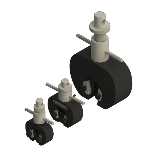 Wedge grip5, 20 and 200 kN
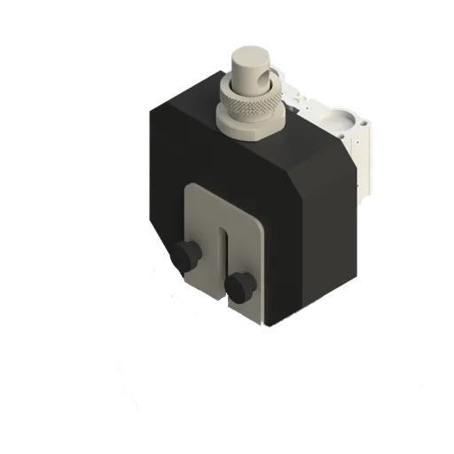 Pneumatic wedge grip50 and 200 kN
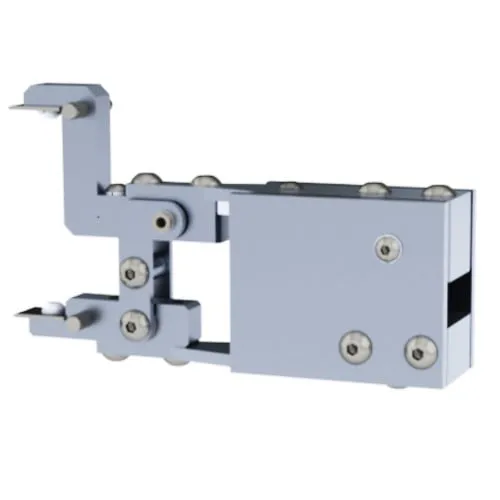 Extensometergauge lengths from 25 to 250 mm
| Application | Range | Biopdi model |
|---|---|---|
| Films, yarns and tapes | 200 N to 1 kN | MBIOI-1P-M2 |
| Polymers, elastomers, textiles, wood | 2 to 10 kN | MBIOI-10-M2 |
| Metals in tension at room temperature | 5 to 50 kN | MBIOII-50-M2 |
For specific configurations, talk to Biopdi about special projects.
Other tests and technical references
Tests performed on the Biopdi universal testing machine



















Related technical references
Compression test: what it is, how to calculate it, concrete (NBR 5739 and fck) and standards
A compression test shortens a specimen until it fractures or yields. Learn to calculate compressive strength, plus NBR 5739, concrete fck and standards.
Test specimen: what it is, types by test and material, standards and dimensions
A test specimen is a sample whose shape and dimensions are set by the test standard. See types, standards and sizes for metal, plastic, concrete, wood and welds.
ASTM D790: three-point flexural test of plastics (procedures A and B, support span and calculations)
ASTM D790-25 measures the flexural strength and flexural modulus of plastics using a bar on two supports loaded at midspan. The support span is 16 times the thickness. The strain rate is 1%/min (procedure A) or 10%/min (procedure B), and the test runs until the specimen breaks or reaches 5% strain. Covers the crosshead speed R = ZL²/6d, the formulas, the large-deflection correction, a comparison with ISO 178 and D6272, and worked examples.
Frequently asked questions
What is a creep test?
It is the test that applies a constant force, at constant temperature, and records the material's strain over time, sometimes up to rupture. For metals it follows ASTM E139 or ISO 204; for plastics, ISO 899 or ASTM D2990.
How is a creep test performed?
The test specimen is heated in a furnace until the temperature stabilizes, receives a constant load (by dead weight or force control), and an extensometer records the elongation for hours or thousands of hours. For plastics and concrete, the test is done at room temperature.
What is the concept of creep?
Creep is the permanent deformation that increases over time in a material under constant stress. In metals, it becomes relevant above about 0.4 of the absolute melting temperature; in lead, polymers and concrete, it already occurs at room temperature.
What is creep in steel?
It is the slow deformation of steel under sustained load at high temperature. In carbon steel, it begins at around 427 °C; in alloy and stainless steels, above 500 °C. That is why boilers and steam piping use creep-resistant steels such as P91.
What are the three stages of the creep curve?
Primary, in which the strain rate decreases; secondary, with a minimum and approximately constant rate, the longest stage; and tertiary, in which the rate accelerates due to internal damage until rupture.
What is creep rate?
It is the strain rate, dε/dt. In practice, the minimum rate of the secondary stage is used, in h⁻¹ or %/h. A rate of 10⁻⁵ %/h is a common creep strength criterion.
What is creep strain?
It is the portion of strain that accumulates after loading, with the load held: the total strain minus the instantaneous strain at the moment the load was applied.
What is the Larson-Miller parameter?
It is LMP = T·(C + log tr), with T in kelvin, tr in hours and C ≈ 20 for low-alloy steels. It combines time and temperature so that short, hot tests can be used to predict service life, which is longer and cooler.
What is the difference between creep and stress relaxation?
In creep, the load is constant and the strain grows. In relaxation, the strain is constant and the stress drops, as in a bolt that loses its preload at high temperature.
Is creep the same as fatigue?
No. Fatigue is caused by cyclic loading and is measured in number of cycles; creep is caused by sustained loading and is measured in time. The two can act together in components at high temperature.
Do plastics creep?
Yes, even at room temperature. That is why the design of plastic parts uses the creep modulus and the isochronous curves of ISO 899, and pressure pipes are sized by the long-term strength from ISO 9080.
Does concrete creep?
Yes. Under sustained load, the strain of concrete keeps growing for months and years. NBR 6118 (the Brazilian design standard for concrete structures) quantifies this with the creep coefficient φ, which can exceed 2 in ordinary environments.