
ABNT NBR 5739:2018, reaffirmed by ABNT in December 2023, is the Brazilian standard for the compression test of cylindrical concrete test specimens. It requires the cylinder to be kept moist until testing and loaded continuously, without shock, at 0.45 ± 0.15 MPa/s until it breaks. The strength is calculated as fc = 4F / (πD²), in MPa, to three significant figures. It applies to cylinders molded under NBR 5738 and to cores drilled from the structure under NBR 7680-1.
This guide summarizes, in our own words, what NBR 5739 requires of the machine, the specimen, the test procedure, the calculation and the report. It also covers the three standards people usually look up alongside it:
- NBR 7222:2011, splitting tensile test of cylinders, current and reaffirmed in April 2024;
- NBR 12142:2010, flexural tensile strength of prisms, current and reaffirmed in April 2024;
- NBR 12118:2013, test methods for hollow concrete blocks, withdrawn in February 2026 and replaced by ABNT NBR 6136-2:2026.
We checked the status of these standards on September 30, 2026, in the catalog of Target (an ABNT reseller) and with ASTM and ISO. The text quotes only the essential figures and is no substitute for the purchased standard.
What NBR 5739 defines and where it fits in concrete quality control
NBR 5739 is the standard for breaking the specimen. Molding, sampling and acceptance of the concrete each have their own standard, and the result is only valid if the whole chain is followed:
- NBR 5738:2015 (molding and curing). Covers how to mold and cure cylindrical and prismatic specimens and how to prepare the ends before testing. Current, reaffirmed in April 2024.
- NBR 5739:2018 (testing). Covers how to break the cylinder and calculate the compressive strength, fc.
- NBR 12655:2022 (control and acceptance). Covers how many specimens to mold, how to group them, how to treat the set of results and when a concrete lot is accepted.
- NBR 7680-1:2015 (cores). Applies when the concrete fails the NBR 12655 criteria: it covers how to drill cylinders from the finished structure and how to correct the result. The core is broken under NBR 5739.
The compression test in general, the stress-strain curve of concrete and the statistical meaning of fck (the characteristic strength, which has a 95% probability of being exceeded) are explained in our guide to compression testing. Here the focus is on what the standard requires and how it differs from its neighbors. The modulus of elasticity is also left out: it is measured on the same type of cylinder, but under another standard, NBR 8522-1, with extensometers on the specimen and load cycles. That test is covered in the article on the modulus of elasticity of concrete.
What NBR 5739 requires of the testing machine
The standard does not specify a make or type of machine, but it sets three performance requirements. The first is the class. Under ABNT NBR ISO 7500-1:2023, the machine is verified with reference instruments, and the class sums up the force indication error: the lower the number, the smaller the permitted error. NBR 5739 requires:
- class 1 or better in a testing laboratory;
- class 2, accepted in a laboratory set up on a job site or at a ready-mix concrete plant;
- calibration to NBR ISO 7500-1 at intervals of no more than 12 months, with an additional calibration recommended whenever an error is suspected, after maintenance or when the machine is moved.
The class belongs to the verified machine, not just to the load cell. A class 1 load cell is a necessary condition, but what counts for the standard is the certificate for the assembled machine, issued by the NBR ISO 7500-1 verification, stating the force range over which the class was achieved. The expected failure load must fall within that range.
The second requirement concerns the platens, made of steel with a surface hardness of at least 55 HRC. The smallest dimension of each platen is at least 4% larger than the specimen diameter: 104 mm for the 100 mm cylinder and 156 mm for the 150 mm cylinder. The contact face is flat, with a maximum deviation of 0.05 mm per 150 mm. The lower platen is removable, has parallel faces and a thickness of at least 10 mm or 10% of the largest diameter tested, and may carry engraved concentric circles to center the specimen: the outer circle is 4 mm larger in diameter than the cylinder, and the grooves are shallow, no more than 0.7 mm deep and 1.0 mm wide.
The third is the spherical seat. The upper platen rests on a spherical seat whose diameter is at least equal to that of the specimen and whose center lies on the machine axis, at the platen face. Under a seating force of only 0.1% of the estimated failure load, the platen must rotate freely by at least 4° in any direction; once seated, it must no longer move. Lubrication is with ordinary mineral oil only: grease and extreme-pressure lubricants are prohibited. The reasoning behind these figures is in the section on interpreting the standard, further on.
The list is completed by these points: the moving platen travels vertically, on the axis of the fixed platen; the adjustable opening between the platens exceeds the specimen height by at least 15 mm; and the indicator shows the maximum force after failure.
Test specimen: what must be ready before testing
The specimen arrives at the test already molded and cured under NBR 5738, in the usual sizes of 10 × 20 cm or 15 × 30 cm, with a height equal to twice the diameter. NBR 5739 adds five checks.
Moisture. The cylinder stays in moist or saturated curing until testing and is broken right after it is removed. If the ends are prepared beforehand, it goes back to the curing condition until it is tested.
Measured dimensions. The diameter used in the calculation is the average of two orthogonal diameters measured at mid-height, to an accuracy of 0.1 mm. The height is measured along the specimen axis, also to 0.1 mm, and includes the capping. The instrument is a caliper with a resolution of 0.1 mm or better, calibrated at intervals of no more than 24 months, because the measuring faces wear with use. The area comes from the diameter measured on the specimen itself, not the nominal one: a diameter of 100.5 mm instead of 100.0 mm changes the area by 1%.
Slenderness ratio h/d. The ratio of height to diameter must be between 1.94 and 2.06. Above 2.06 the specimen is rejected. Below 1.94, which happens with cores drilled from slabs, the test is performed and the force is corrected by a factor, explained in the calculation section. This same range of 1.94 to 2.06 allows molded cylinders to go unmeasured when the laboratory controls mold geometry under NBR 5738: in that case the nominal dimensions apply.
Ends. Both faces in contact with the platens must be flat and perpendicular to the axis. End preparation is not covered by NBR 5739: it follows NBR 5738, or NBR 7680-1 for cores, by grinding (with a diamond wheel) or by capping (a thin, bonded layer that levels the face). NBR 5739 only requires the type of preparation to be stated in the report. Medeiros, Pereira, Sipp and Delfino (2017, Revista IBRACON de Estruturas e Materiais) compared four preparation methods on 10 × 20 cylinders from 20 to 80 MPa. Grinding reached the expected strength in almost every case, with the lowest scatter; neoprene pads in a metal retainer, an unbonded bearing, came in behind it. NBR 5739 does not address neoprene: if the laboratory uses it, whether it is permitted and under what conditions is set by the current edition of NBR 5738, together with the laboratory's own procedure.
Age. The specimen is broken at the specified age, counted from molding, and each age has a tolerance. The 28-day age is the reference for fck; the others track strength development or meet design specifications. The table summarizes the NBR 5739 tolerances; for an age not listed, the tolerance is interpolated:
| Test age | Tolerance |
|---|---|
| 24 h | ± 0.5 h |
| 3 days | ± 2 h |
| 7 days | ± 6 h |
| 28 days | ± 24 h |
| 63 days | ± 36 h |
| 91 days | ± 48 h |
Test procedure: centering and loading rate
With the cylinder ready, the operator makes sure the platens and the ends are clean and dry and centers the specimen on the lower platen using the concentric circles engraved on it. Off center, it is subjected to bending in addition to compression and fails prematurely. If the ends were ground by abrasion, the face that was the top during molding is marked beforehand so the orientation is not lost.
Loading is continuous and without shock, with the stress increasing at 0.45 ± 0.15 MPa/s, and the rate is held constant until failure. The standard specifies stress so it applies to any diameter, but the machine controls force: the rate in kN/s is the rate in MPa/s multiplied by the area in mm² and divided by 1,000. The table shows the two usual sizes:
| Test specimen | 0.30 MPa/s | 0.45 MPa/s | 0.60 MPa/s |
|---|---|---|---|
| 10 × 20 cm (A = 7,854 mm²) | 2.36 kN/s | 3.53 kN/s | 4.71 kN/s |
| 15 × 30 cm (A = 17,671 mm²) | 5.30 kN/s | 7.95 kN/s | 10.6 kN/s |
The rate also sets the test duration: the time to failure is the strength divided by the rate. The chart below shows a 10 × 20 cylinder of 30 MPa at the three rates in the range. In all three cases the maximum force is the same, 235.6 kN, but failure comes at 100 s at 0.30 MPa/s, at 67 s at 0.45 MPa/s and at 50 s at 0.60 MPa/s. After the peak the force drops at once, because concrete is brittle, and that drop is what tells the software the test has ended.
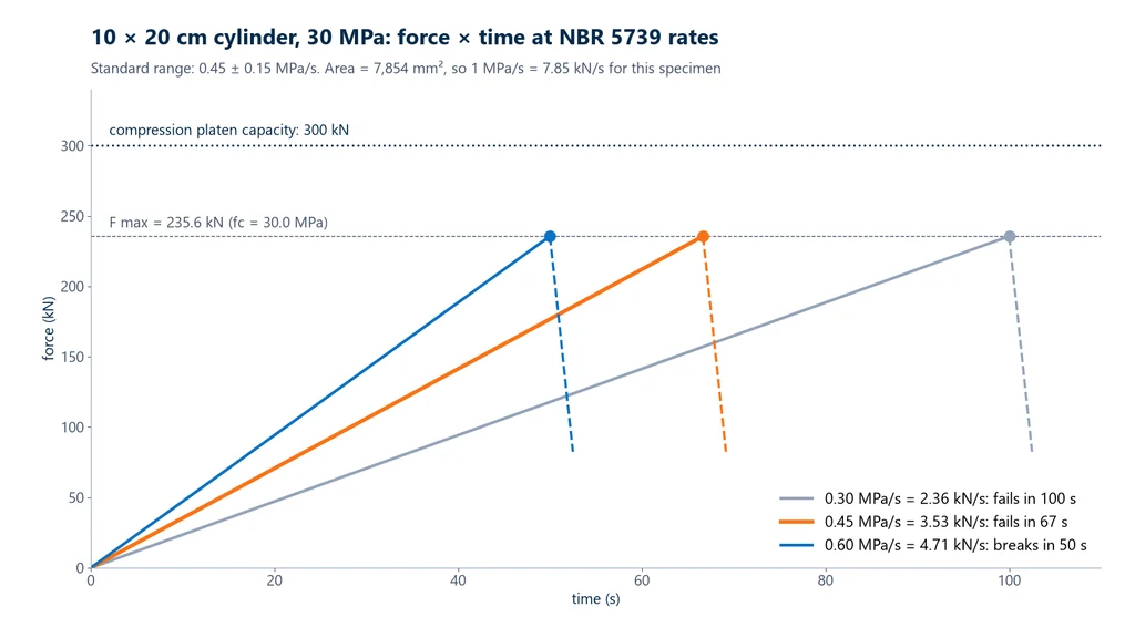
The chart is idealized: in practice, the measured strength rises slightly with the rate. A survey published by Supremo Cimentos reports differences on the order of 5% when the rate goes from 0.2 to 0.8 MPa/s, compared with 0.45 MPa/s. That is why the rate is not a procedural detail: loading too fast overestimates fc, and the range set by the standard is what makes results from different laboratories comparable.
Calculating fc and the h/d correction
Compressive strength is the maximum force divided by the cross-sectional area. For a cylinder, the area is πD²/4, which gives the formula in the standard:
fc = 4F / (π·D²), with F, the maximum force, in newtons, and D, the average measured diameter, in millimeters. Since 1 N/mm² = 1 MPa, the result comes out directly in MPa and is reported to three significant figures: 36.3 MPa, not 36.338 MPa or 36 MPa.
Rearranging the formula, F = fc · πD²/4 gives the force each concrete class requires. This is the number that determines the machine capacity, and the table shows it for the two usual cylinders:
| fc | 10 × 20 cylinder | 15 × 30 cylinder |
|---|---|---|
| 20 MPa | 157.1 kN | 353.4 kN |
| 25 MPa | 196.3 kN | 441.8 kN |
| 30 MPa | 235.6 kN | 530.1 kN |
| 40 MPa | 314.2 kN | 706.9 kN |
| 50 MPa | 392.7 kN | 883.6 kN |
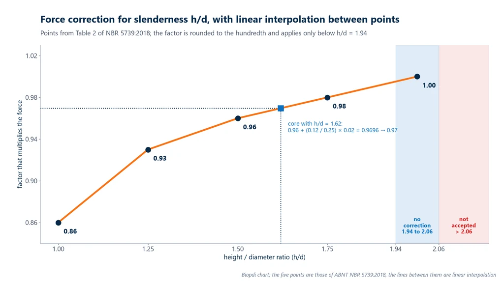
Slenderness correction. A cylinder shorter than standard fails at a higher force, because friction with the platens confines a larger share of its volume. When h/d is below 1.94, NBR 5739 requires the force to be multiplied by the factor in the table below before calculating fc; for intermediate values, interpolate linearly between the points in the table and round the factor to the nearest hundredth. A specimen with h/d between 1.94 and 2.06 needs no correction.
| h/d | Force correction factor |
|---|---|
| 2.00 | 1.00 |
| 1.75 | 0.98 |
| 1.50 | 0.96 |
| 1.25 | 0.93 |
| 1.00 | 0.86 |
The chart below connects the five points of the table with straight lines, which is what linear interpolation does, and marks the two ranges where the table does not apply: from 1.94 to 2.06 there is no correction, and above 2.06 the specimen is rejected. In the highlighted example, a core with h/d = 1.62, between the 1.50 and 1.75 points, gets a factor of 0.97; the calculation is in exercise 3.
Failure types A to G
After failure, the laboratory examines the cracks. Annex A of NBR 5739, which is informative, classifies the appearance of the broken cylinder into seven types, A to G. Recording the type in the report is optional, but it is the quickest way to find the cause when two specimens from the same batch, broken at the same age, give very different results. The diagram below, drawn for this guide and not copied from the standard, shows the typical fracture lines for each type. In A, the two cones may start in the capping itself or within 25 mm of it; in F and G, the fracture runs close to one end, just below the capping:
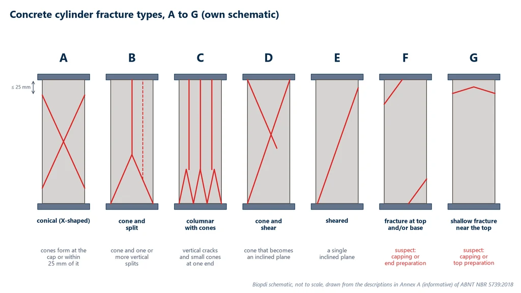
The table gives the practical reading of each type:
| Type | Appearance | What it usually indicates |
|---|---|---|
| A | cone, X-shaped, with cones starting at the capping or within 25 mm of it | well-performed test |
| B | cone, with one or more vertical splits | normal failure |
| C | columnar, with vertical cracks and cone formation | vertical cracks; low friction at the ends |
| D | cone and shear | mixed failure |
| E | shear, along an inclined plane | check end parallelism and the spherical seat |
| F | fracture at the top and/or bottom, just below the capping | capping or end preparation problem |
| G | shallow fracture near the top | same as F, concentrated at the top |
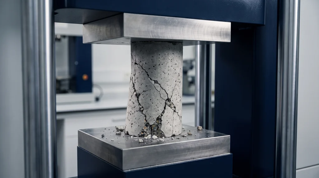
The standard associates high scatter between specimens with types F and G, but it does not require a result to be discarded because of the failure type. The right response to a run of F and G failures is to review the capping, the end preparation and the molding of the top, not to delete the number. The photo shows a cylindrical concrete specimen just after failure, still between the platens of the press: the inclined cracks and the loose fragments near the bottom are the kind of evidence the laboratory compares with the diagram above before recording the type in the report.
What the NBR 5739 test report must include
The report is what reaches the client and the structural designer, and ABNT NBR 5739 (the Brazilian standard for compression testing of cylindrical concrete specimens) sets its minimum content:
- specimen identification;
- molding and testing dates, and the age;
- measured dimensions (diameter and height);
- type of capping or end preparation;
- testing machine class;
- compressive strength of each specimen, in MPa.
Two items are optional: the strength of the test sample calculated per NBR 12655 (the Brazilian standard for concrete preparation, control and acceptance; the test sample is the pair of specimens covered in the next section) and the fracture type from Annex A. For drilled cores, the report follows the requirements of NBR 7680-1 (the Brazilian standard for extraction and testing of concrete cores).
From test result to lot acceptance (NBR 12655)
A single fc value does not accept or reject concrete. Under NBR 12655:2022, each test sample consists of two specimens from the same batch, tested at the same age, and the strength of the test sample is the higher of the two values, not the average: the lower one is attributed to molding or testing, not to the concrete. From the test samples of the lot, the standard estimates fck; with 20 or more test samples, fck,est = fcm − 1.65·sd, where fcm is the mean and sd the standard deviation. The numerical example and the meaning of "fck 30 MPa" are in the compression test guide.
Annex B: test efficiency measured by the coefficient of variation
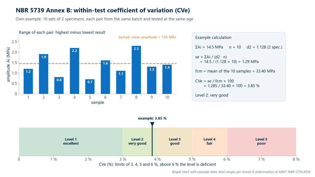
Annex B of NBR 5739, also informative, gives the laboratory a way to assess its own test execution through the scatter between companion specimens, those of the same test sample. Reporting the result is optional. The recommended data set has 10 or more test samples, each with 2 or more specimens, and the calculation has three steps:
- Range of the test sample. Ai is the highest result minus the lowest, within each test sample.
- Within-test standard deviation. se = ΣAi / (d2 · n), where n is the number of test samples and d2 is a coefficient that depends on how many specimens make up the test sample: 1.128 for 2, 1.693 for 3, 2.059 for 4, 2.326 for 5 and 2.534 for 6.
- Within-test coefficient of variation. CVe = se / fcm × 100, in %, where fcm is the mean strength of the test samples in the data set.
CVe is compared with five levels: up to 3.0%, excellent; above 3.0 up to 4.0%, very good; above 4.0 up to 5.0%, good; above 5.0 up to 6.0%, fair; above 6.0%, poor. The chart below shows an example built for this guide, with 10 test samples of 2 specimens each: the bars are the ranges, the box shows the calculation and the scale at the bottom shows that the result, 3.85%, falls into level 2. The full calculation is in exercise 8.
Sister standards: how the tensile strength of concrete is measured
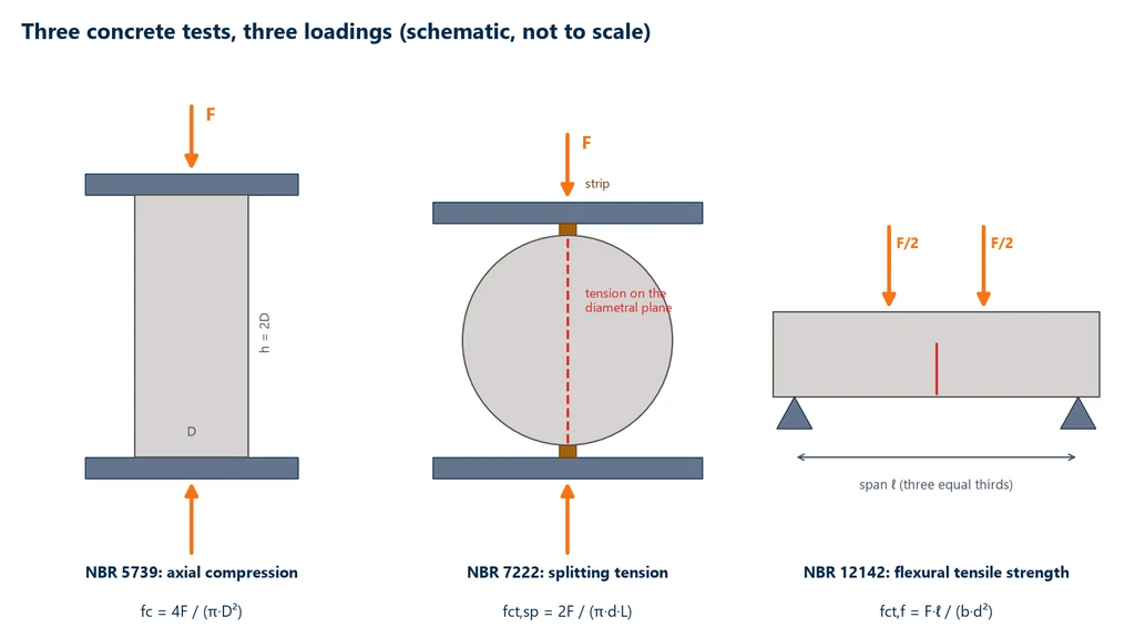
Concrete is weak in tension, about one tenth of its compressive strength, and it is hard to pull it directly: gripping a brittle cylinder concentrates stress and breaks it in the wrong place. That is why tensile strength is measured indirectly, by two tests that also use compression applied by the machine: the splitting tensile test of NBR 7222 and the flexural test of NBR 12142. The diagram below shows side by side the upright cylinder of NBR 5739, the cylinder lying between bearing strips of NBR 7222, in tension on the vertical diametral plane, and the prism loaded at the third points of the span of NBR 12142, in tension on the bottom face.
NBR 7222: splitting tensile test
ABNT NBR 7222:2011, Concrete and mortar: Determination of the tensile strength by diametral compression of cylindrical test specimens (the Brazilian splitting tensile test standard), is in force and was confirmed in April 2024. It is known as the Brazilian test, because the method was proposed in Brazil by Fernando Lobo Carneiro. It uses the same cylinders as NBR 5739, of concrete or mortar, and the same platens, with a length-to-diameter ratio between 1 and 2. The complete test, with the bearing strips, the rate in kN/s, the conversion per NBR 6118 and exercises, is in the NBR 7222 guide.
The cylinder is laid on its side between the platens, with a hardboard strip above and another below, of length equal to or greater than the line of contact along the cylinder. The standard sets the strip width at (0.15 ± 0.01) d and the thickness at (3.5 ± 0.5) mm, and each strip is used for a single test. When the machine platen is shorter than the cylinder, a supplementary machined steel bar or plate is added, at least 50 mm thick, so that the load acts along the whole line of contact. With the load applied along a line, the central region of the vertical diametral plane is under nearly uniform tension, and the cylinder splits in half along that plane.
The tensile stress increases at 0.05 ± 0.02 MPa/s, nine times slower than in NBR 5739, and the strength is:
fct,sp = 2F / (π·d·L), with F in N, d (diameter) and L (length) in mm, and the result in MPa, to three significant figures. The standard recommends testing at least 2 specimens per age.
The value is an indirect tensile strength: NBR 6118 (the Brazilian concrete structural design standard) applies a factor to obtain the direct tensile strength for design, as the comparison further on shows.
NBR 12142: flexural tensile strength of prisms
ABNT NBR 12142:2010, Concrete: Determination of the flexural tensile strength of prismatic test specimens (the Brazilian standard for concrete flexural strength), is in force and was confirmed in April 2024. This is the strength used in the mix design of concrete pavements, where the slab works in bending. The theory behind the flexural test, with the difference between 3-point and 4-point bending, is in the flexural test guide. The complete test, with the 4-point fixture, the rule on fracture location and exercises, is in the NBR 12142 guide.
The usual specimen is a 150 × 150 × 500 mm prism, molded per NBR 5738 (the Brazilian standard for molding and curing concrete specimens), supported on a 450 mm span and loaded by two equal forces at the third points of the span. NBR 12142 ties the geometry together: the prism depth is one third of the span (150 = 450/3) and at least 25 mm must extend beyond each support, which is exactly what the 500 mm prism leaves. Between the two forces the bending moment is constant, so the whole middle third is under the same maximum stress, and the prism breaks at the weakest point of that region, not under a loading roller.
Supports and loading rollers have a 12.5 mm radius, are 3 to 5 mm longer than the prism width, with at least 55 HRC. One support and one loading roller pivot in all directions, by at least ±4°, and the other two only along the length, with a seating force of no more than 0.1% of the failure load, the same criterion as the spherical seat of NBR 5739. The prism is turned 90° relative to its molding position: the side faces of the mold receive the load, and the struck-off face is on the side. The stress increases at 0.9 to 1.2 MPa/min, without shocks. After fracture, b and d are measured at the fractured section, to 1 mm, as the average of three readings, and the result is given to three significant figures.
- Fracture in the middle third: fct,f = F·ℓ / (b·d²), with ℓ the span between supports.
- Fracture outside the middle third, by no more than 5% of ℓ: fct,f = 3·F·a / (b·d²), where a is the average distance between the fracture line, on the tension face, and the nearest support.
- Fracture farther away than that: the standard provides no calculation, and the test is invalid.
Comparison of the three standards and the link with NBR 6118
The three standards use the same machine and, in part, the same specimen, but they measure different things at very different rates. The table summarizes what the previous sections explained:
| Standard | Specimen and loading | Rate | Result |
|---|---|---|---|
| NBR 5739:2018 | upright cylinder, axial compression | 0.45 ± 0.15 MPa/s | fc = 4F / (πD²) |
| NBR 7222:2011 | cylinder on its side, indirect tension | 0.05 ± 0.02 MPa/s | fct,sp = 2F / (πdL) |
| NBR 12142:2010 | prism, third-point bending | 0.9 to 1.2 MPa/min | fct,f = Fℓ / (bd²) |
Both tensile tests give values higher than the direct tensile strength of concrete: in bending, only the outer fiber reaches the maximum stress, and the surrounding material helps; in splitting, the stress state is biaxial. NBR 6118:2023 (with the March 2026 amendment), the Brazilian design standard for concrete structures, converts both results into direct tensile strength with fct = 0.9·fct,sp and fct = 0.7·fct,f. Without testing, the same standard estimates the mean tensile strength from fck, for concretes up to C50, as fct,m = 0.3·fck2/3. The exercises further on show that the three routes give consistent values for a 30 MPa concrete.
Concrete blocks: from NBR 12118 to NBR 6136-2:2026
ABNT NBR 12118, Hollow plain concrete blocks for masonry: Test methods (the former Brazilian test standard for concrete masonry blocks), had its last edition in 2013 (with a corrigendum in 2014) and was confirmed in 2017 and 2022. In February 2026 it was withdrawn and replaced, according to the standard's history in the Target standards catalog.
The block test methods moved to ABNT NBR 6136-2:2026, Hollow concrete blocks for masonry, Part 2: Test methods, published in February 2026, in force, with 29 pages. It covers visual inspection, dimensional analysis, compressive strength, initial rate of absorption, water absorption, net volume, relative moisture and linear drying shrinkage. The requirements the block must meet remained in Part 1, NBR 6136-1:2026, which replaced NBR 6136:2016. According to ABCP (the Brazilian Portland Cement Association), the revision introduced optional lot control requirements and performance requirements, and made NBR 6136 one of the first Brazilian construction product standards with environmental requirements.
Block compression testing does not follow NBR 5739: the specimen is the hollow block itself, with conditioning, face preparation, calculation area and loading rate defined in NBR 6136-2, and the estimated fbk and classes A, B and C come from NBR 6136-1. The step-by-step procedure, based on the full text of both parts, is in the NBR 6136-2 concrete blocks guide.
How to interpret the standard
The text of NBR 5739 is short and gives the numbers without saying where they come from. This section brings together the points that raise the most questions when reading it and the physical or statistical reason behind each one.
Why does the h/d ratio change the strength, and how is it corrected?
The steel platens are much stiffer than concrete and, through friction, prevent the ends of the cylinder from expanding sideways. Next to each platen a confined, cone-shaped region forms that is stronger than unconfined concrete. In a cylinder with h/d = 2, the two cones almost meet and an unconfined band remains in the middle, where failure starts. In a short cylinder, the cones overlap, almost the whole volume is confined and the failure load rises. The factor in Table 2 of the standard discounts this gain: 0.86 for h/d = 1.00 means that a core as tall as it is wide fails at about 16% more load than the standard cylinder of the same concrete (1/0.86 = 1.16). The range from 1.94 to 2.06, 3% around 2, is treated as standard and needs no correction; above it the standard gives no factor, and the specimen is rejected.
Why does the upper platen have a spherical seat, and what does the 0.1% limit mean?
No pair of ends is perfectly parallel. With two fixed platens, contact would start at one edge, and the load would be eccentric, adding bending to compression. The spherical seat lets the upper platen rotate and bear on the whole end at the start of loading; its 4° of movement easily covers the lack of parallelism that capping or grinding leaves. The limit of 0.1% of the estimated failure load is the test that the seat is free: it must seat with a very small force, about 0.24 kN for a 10 × 20 cylinder of 30 MPa concrete. A stuck seat would only rotate under a high force, when the edge is already loaded. Once seated, the platen must stay locked by friction: if it kept rotating, it would follow the side that gives way and induce bending. Grease and extreme-pressure lubricant are prohibited precisely because they keep the ball sliding even under the test load.
What is the practical difference between a class 1 and a class 2 machine?
The class comes from verification per ISO 7500-1 (ABNT NBR ISO 7500-1 in Brazil) and sums up, among other criteria, the relative error of force indication: up to 1% for class 1 and up to 2% for class 2. Since fc is proportional to force, this error carries over fully to the result: for a 30 MPa concrete, 1% is 0.3 MPa and 2% is 0.6 MPa. NBR 5739 requires class 1 or better for testing laboratories and accepts class 2 only for site laboratories and ready-mix concrete plants. The difference matters when the result is close to the specified fck, which is why the class is a mandatory item of the report.
Why does the age tolerance increase with age?
Because what matters is the relative error. In proportion to age, the tolerances in Table 1 of the standard all fall between 2% and 4%: half an hour at 24 h is 2.1%; 2 h at 3 days, 2.8%; 6 h at 7 days and 24 h at 28 days, 3.6%; 36 h at 63 days, 2.4%; 48 h at 91 days, 2.2%. Concrete gains strength quickly in the first days and slowly afterwards, so one hour of difference matters for a 24 h cylinder and is irrelevant for a 28-day one, whose strength gain curve is already nearly flat. And age is counted from molding, not from arrival at the laboratory.
What does the Annex B CV say about the laboratory, and not about the concrete?
The specimens of a test sample come from the same batch and are tested at the same age: the concrete inside them is, in practice, the same. The difference between them comes from what happened after mixing: molding, consolidation, curing, end preparation, centering and the machine. That is why CVe measures the quality of the testing operations, not the uniformity of the concrete. The batch-to-batch variability of the concrete is another quantity, the standard deviation sd of NBR 12655, calculated between test samples. The coefficient d2 comes from statistical quality control: dividing the average range of small groups by d2 estimates the standard deviation, and d2 grows with group size because the more specimens there are, the greater the expected distance between the highest and the lowest. A CVe above 6% points to the molding and testing operations, not to the concrete mix design.
What do fracture types F and G indicate?
In types A to E, the fracture runs through the specimen, and failure was governed by the concrete. In F and G, the fracture stays close to one end, just below the capping: stress concentrated at the end, which gave way before the rest of the cylinder reached its limit. The usual causes are irregular, thick, soft or poorly bonded capping, an end out of square and, at the top, the weaker upper layer left by bleeding (water from mixing rising to the molding face) when consolidation or finishing was not done properly. That is why the standard links high scatter within a test sample to these two types: the low value reflects the end, not the concrete.
Worked examples
1. fc of a 10 × 20 cylinder. Measured mean diameter of 100.0 mm, maximum force of 285.4 kN. The area is π × 100.0² / 4 = 7,854 mm². fc = 285,400 / 7,854 = 36.34 MPa, which is reported to three significant figures as 36.3 MPa.
2. Programmed rate and duration. For the same cylinder at 0.45 MPa/s, the machine applies 0.45 × 7,854 = 3,534 N/s, or 3.53 kN/s. A 30 MPa concrete fails in 30 / 0.45 = 67 s, at a force of 30 × 7,854 = 235,619 N, or 235.6 kN.
3. Short core. A core 100 mm in diameter and 150 mm high has h/d = 1.50, below 1.94, so the factor is 0.96. It failed at 250.0 kN. Corrected force: 250,000 × 0.96 = 240,000 N. fc = 240,000 / 7,854 = 30.6 MPa. Without the correction, the result would be 31.8 MPa, and the concrete would appear 4% stronger than it is. With interpolation: another core, 100.0 mm in diameter, is 162 mm high, h/d = 1.62, between the 1.50 and 1.75 points. The factor is 0.96 + (1.62 − 1.50) / (1.75 − 1.50) × (0.98 − 0.96) = 0.96 + 0.48 × 0.02 = 0.9696, which rounds to 0.97 at the nearest hundredth. If it failed at 260.0 kN, the corrected force is 260,000 × 0.97 = 252,200 N, and fc = 252,200 / 7,854 = 32.1 MPa, versus 33.1 MPa without the correction.
4. Splitting tensile test (NBR 7222). 10 × 20 cylinder lying on its side, F = 75.0 kN. fct,sp = 2 × 75,000 / (π × 100 × 200) = 150,000 / 62,832 = 2.39 MPa. Direct tensile strength per NBR 6118 (the Brazilian concrete structures design code): 0.9 × 2.39 = 2.15 MPa. The rate of 0.05 MPa/s corresponds to 0.05 × π × 100 × 200 / 2 = 1,571 N/s, about 1.57 kN/s.
5. Flexural tensile strength (NBR 12142). 150 × 150 mm prism, 450 mm span, F = 30.0 kN, failure in the middle third. fct,f = 30,000 × 450 / (150 × 150²) = 13,500,000 / 3,375,000 = 4.00 MPa, and the direct tensile strength is 0.7 × 4.00 = 2.80 MPa. If the same prism failed 140 mm from the nearest support, 10 mm outside the middle third (which starts at 150 mm) and within the limit of 5% of 450 mm, or 22.5 mm: fct,f = 3 × 30,000 × 140 / 3,375,000 = 3.73 MPa. The rate of 0.9 to 1.2 MPa/min corresponds, for this prism, to 6.75 to 9.0 kN/min.
6. Consistency with the design. For fck = 30 MPa, NBR 6118 estimates fct,m = 0.3 × 302/3 = 0.3 × 9.655 = 2.90 MPa, between the 2.15 MPa and 2.80 MPa of examples 4 and 5.
7. Machine capacity. A laboratory tests 10 × 20 cylinders of C25 and C30 concrete, proportioned under condition A of NBR 12655 (the Brazilian standard for concrete preparation, control and acceptance; standard deviation of 4.0 MPa, target mean fck + 1.65 × 4.0). The machine must cover not only the mean but also the results above it: about 5% of the cylinders exceed mean + 1.65 × 4.0.
- C25: mean of 31.6 MPa, or 248 kN. Upper limit of 38.2 MPa, or 300 kN. 300 kN platens are sufficient, with no margin at the extreme.
- C30: mean of 36.6 MPa, or 287 kN. Upper limit of 43.2 MPa, or 339 kN. The mean fits within 300 kN, but some cylinders would exceed the capacity: the right machine is the 600 kN one.
- 15 × 30 at 30 MPa: 530 kN for the nominal value alone. This calls for a 600 kN machine for low strength classes and a 1,000 kN machine for high strength classes.
8. Test efficiency per Annex B. A laboratory collected 10 samples of 2 test specimens each. The ranges, in MPa, were 1.2, 1.9, 0.8, 2.2, 0.7, 1.6, 1.1, 2.3, 1.3 and 1.4, summing to 14.5 MPa. The sample values, the higher of each pair, were 33.0, 32.8, 34.1, 32.6, 33.2, 33.1, 34.8, 33.9, 32.0 and 34.5 MPa, with mean fcm = 334.0 / 10 = 33.40 MPa. With 2 test specimens per sample, d2 = 1.128:
- se = 14.5 / (1.128 × 10) = 14.5 / 11.28 = 1.29 MPa;
- CVe = 1.285 / 33.40 × 100 = 3.85%, above 3.0% and up to 4.0%: level 2, very good;
- using the mean of all 20 test specimens, 653.5 / 20 = 32.68 MPa, the CVe would be 3.93%, at the same level.
Common mistakes when applying NBR 5739 and its companion standards
The most frequent mistakes in reports, procedures and public tender documents in Brazil:
- Citing an old edition. The current NBR 5739 is the 2018 edition, reaffirmed in 2023; the 2007 edition still appears in papers and procedures.
- Using a third-party PDF as the reference. Copies of the standard circulate on file-sharing sites, with no guarantee of edition and no right of use. A laboratory's reference is the standard purchased from ABNT.
- Programming the wrong rate in kN/s. 3.53 kN/s is the rate for the 10 × 20; used on a 15 × 30, it gives 0.20 MPa/s, outside the range.
- Averaging the two test specimens of a sample. Under NBR 12655, the higher value counts.
- Discarding a result based on the fracture type. The standard does not call for discarding it; types F and G call for a review of specimen molding and end preparation.
- Confusing a class 1 load cell with a class 1 machine. What counts is the certificate of the machine verified per NBR ISO 7500-1.
- Greasing the spherical seat. The standard allows only ordinary mineral oil; grease and extreme-pressure lubricants let the platen rotate during the test.
- Taking the h/d factor from the nearest point in the table. Between points, the factor is linearly interpolated and rounded to the nearest hundredth.
- Treating fct,sp or fct,f as direct tensile strength. Both require the 0.9 and 0.7 factors of NBR 6118.
- Mixing up the numbers 7222 and 12142. 7222 is the cylinder lying on its side; 12142, the prism in flexure.
- Citing NBR 12118 as current. It was withdrawn in February 2026; the tests for concrete blocks are now in NBR 6136-2:2026.
- Citing ASTM C496 as current. It was withdrawn by ASTM in July 2026, with no replacement.
Equipment for NBR 5739, NBR 7222 and NBR 12142
The three tests can be run on two types of equipment. The electric-hydraulic concrete compression testing machine is dedicated to compression and handles routine cylinder breaking. The dual-column universal testing machine runs all three tests on the same frame by changing the accessory: 300 kN compression platens for NBR 5739 and, with the bearing strips, for NBR 7222; a 300 kN flexural fixture, in 4-point configuration, for NBR 12142.
Capacity follows example 7: a 10 × 20 cylinder at 30 MPa requires about 236 kN, within the 300 kN platens, and a 150 mm prism fails in the 30 to 45 kN range. 15 × 30 cylinders and high strength classes call for the 600 kN machine or the 1,000 kN one; for 10 × 20 cylinders up to C30, the reference is the 300 kN machine. The load cell of the M2 line is class 1 per ABNT NBR ISO 7500-1:2023 (the Brazilian adoption of ISO 7500-1); the class of the assembled machine comes from verification by the calibration laboratory, as NBR 5739 requires. The BioLab software converts the rate in MPa/s to kN/s from the measured diameter, calculates fc, fct,sp and fct,f and generates the report. The panel below shows the machine, the role of each part in these tests and the two accessories used.
The universal testing machine in the compression test
The dual-column M2 line ranges from 5 kN to 1,000 kN. In the NBR 5739, NBR 7222 and NBR 12142 tests, each part of the machine has a function:

- Moving crosshead applies the load at the MPa/s rate set by the standard
- Load cell measures the force, class 1
- Compression platens cylinder upright, or lying between bearing strips
- Flexural fixture prism loaded at the third points
- BioLab software fc, fct,sp, fct,f and report
- Control panel and emergency stop positions the crosshead and stops the test
Fixtures for the compression test
The fixtures below are mounted on the same machine, depending on the test specimen and the standard:
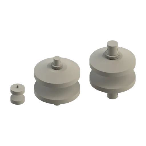
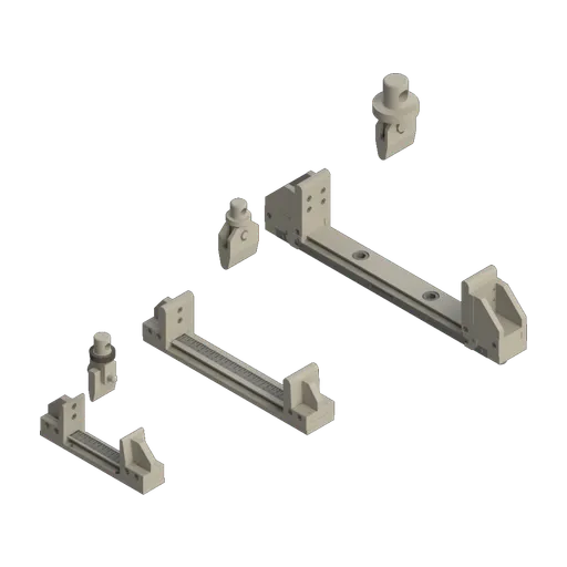
To compare the models, see the universal testing machine guide; the configuration for each standard is defined in the quote.
Standards cited: edition and status as of September 30, 2026
The table lists the standards in this guide, with edition and status checked on September 30, 2026 in the Target catalog (a Brazilian standards distributor) for the ABNT standards, and on the official ASTM and ISO pages. The foreign equivalents do not give interchangeable numbers: ASTM C39, for example, loads at 0.25 ± 0.05 MPa/s, roughly half the Brazilian rate.
| Standard | Subject | Edition and status |
|---|---|---|
| ABNT NBR 5739 | compression of concrete cylinders | 2018, current (reaffirmed 12/2023) |
| ABNT NBR 5738 | making and curing of test specimens | 2015 (erratum 2016), current (reaffirmed 04/2024) |
| ABNT NBR 7680-1 | drilled cores, axial compression | 2015, current (reaffirmed 04/2024) |
| ABNT NBR 12655 | preparation, control, receipt and acceptance | 2022, current |
| ABNT NBR 7222 | splitting tensile strength | 2011, current (reaffirmed 04/2024) |
| ABNT NBR 12142 | flexural tensile strength of prisms | 2010, current (reaffirmed 04/2024) |
| ABNT NBR 12118 | test methods for hollow concrete blocks | 2013, withdrawn 02/2026 |
| ABNT NBR 6136-2 | hollow concrete blocks, test methods | 2026, current (replaces NBR 12118) |
| ABNT NBR 6136-1 | hollow concrete blocks, requirements | 2026, current |
| ABNT NBR 6118 | design of concrete structures | 2023, with amendment of 03/2026, current |
| ABNT NBR ISO 7500-1 | verification and class of the machine | 2023, current |
| ASTM C39/C39M | compression of cylinders (USA) | C39/C39M-26, active |
| ASTM C496/C496M | splitting tensile strength (USA) | C496/C496M-17, withdrawn July 3, 2026, no replacement |
| ASTM C78/C78M | flexure with third-point loading (USA) | C78/C78M-22, active |
| ISO 1920-4 | compression, flexure and splitting tension | 2020, confirmed in 2025 |
Other tests and technical references
Tests performed on the Biopdi universal testing machine



















Related technical references
Compression test: what it is, how to calculate it, concrete (NBR 5739 and fck) and standards
A compression test shortens a specimen until it fractures or yields. Learn to calculate compressive strength, plus NBR 5739, concrete fck and standards.
NBR 7222: splitting tensile test, fct,sp calculation, bearing strips and loading rate in kN/s
NBR 7222:2011 measures the tensile strength of concrete and mortar by diametral compression: fct,sp = 2F/(π·d·L) at 0.05 MPa/s. Strips, calculation, examples and machine.
NBR 6136-2: compression test of concrete blocks, fbk, strength classes and what changed from NBR 12118
NBR 6136-2:2026 replaced NBR 12118 in Brazil: hollow concrete block tests, fb = F/Ab on gross area, fbk calculation, classes A, B and C, and what changed.
Frequently asked questions
What is the ABNT standard for concrete compression testing?
It is ABNT NBR 5739:2018, reaffirmed in December 2023. It applies to cylindrical test specimens molded per NBR 5738 and to cores drilled from the structure per NBR 7680-1.
What is the loading rate in NBR 5739?
0.45 ± 0.15 MPa/s, applied continuously and without shock and held constant until failure. For the 10 × 20 cylinder this gives 2.36 to 4.71 kN/s, with 3.53 kN/s at the center of the range; for the 15 × 30, 5.30 to 10.6 kN/s.
How do you calculate the fc of a test specimen?
Divide four times the maximum force by π times the diameter squared: fc = 4F / (πD²), with F in newtons and D in millimeters, which gives MPa. Report to three significant figures: a 10 × 20 that fails at 235.6 kN has 30.0 MPa.
What are the fracture types in NBR 5739?
There are seven, A to G, in informative Annex A: cone, cone and split, columnar with cones, cone and shear, shear, and F and G, with fractures at the top or bottom. F and G usually indicate a capping or end preparation problem; the standard does not call for discarding the result based on the type.
What does NBR 5738 define?
How to mold and cure cylindrical and prismatic concrete test specimens and how to prepare their ends, by grinding or capping. It is the step before breaking per NBR 5739. The current edition is the 2015 one, reaffirmed in 2024.
What is the ABNT standard for concrete curing?
Curing of test specimens is covered by NBR 5738, which calls for moist or saturated curing until the test age. Curing of the structure on site is a matter for the construction standards, not the test standards.
What is the age tolerance for breaking at 28 days?
± 24 h. Under NBR 5739, the other ages have their own tolerances: ± 0.5 h at 24 h, ± 2 h at 3 days, ± 6 h at 7 days, ± 36 h at 63 days and ± 48 h at 91 days.
How many test specimens make up a sample?
Under NBR 12655, two test specimens from the same batch, tested at the same age. The strength of the sample is the higher of the two values, not the mean.
What is NBR 7222?
It is the indirect tensile test method by diametral compression, known internationally as the Brazilian test: the cylinder is laid between two bearing strips and compressed with the tensile stress increasing at 0.05 ± 0.02 MPa/s. The strength is fct,sp = 2F / (π·d·L), and the design direct tensile strength is 0.9 times this value.
What is NBR 12142?
It is the flexural tensile strength test for concrete prisms, supported at the ends and loaded by two forces at the third points of the span. With failure in the middle third, fct,f = F·ℓ / (b·d²). It is the strength used in the mix design of concrete pavements.
Has NBR 12118 been withdrawn?
Yes. It was withdrawn and replaced in February 2026. The test methods for hollow concrete blocks are now in ABNT NBR 6136-2:2026, and the requirements in NBR 6136-1:2026.
What is the ASTM equivalent of NBR 5739?
ASTM C39/C39M, in version C39/C39M-26, with a rate of 0.25 ± 0.05 MPa/s, which makes the results not directly comparable. The equivalent of NBR 7222, ASTM C496/C496M, was withdrawn in July 2026 with no replacement; the equivalent of NBR 12142 is ASTM C78/C78M-22.