
ASTM D638, Standard Test Method for Tensile Properties of Plastics, is the ASTM International method for measuring the tensile properties of reinforced and unreinforced plastics up to 14 mm thick. The current edition is D638-22. It requires dog-bone (dumbbell) test specimens (Types I to V), conditioning at 23 °C and 50% relative humidity, the lowest speed that breaks the specimen within 0.5 to 5 minutes, a Class B-2 extensometer for the modulus, and at least five test specimens. The main result is tensile strength, σ = Fmax / A0, along with elongation and modulus of elasticity.
In short:
- Scope: rigid, semirigid and nonrigid plastics up to 14 mm thick; for films and sheeting less than 1.0 mm thick, the preferred method is ASTM D882.
- Preferred test specimen: Type I, 165 mm long, with a narrow section of 13 × 3.2 mm.
- Speed: 5, 50 or 500 mm/min for Types I to IV; 1, 10 or 100 mm/min for Type V.
- It is not ISO 527: ASTM itself states that the two cover the same subject with different technical content. The test report cites the standard actually performed.
The standard is a paid document sold by ASTM; this guide explains it in our own words, for those who will apply it or buy the equipment, with the essential numerical requirements and the source of each one.
What ASTM D638 is and which edition is current
The tensile test applies an increasing axial force to the test specimen, at a controlled speed, until fracture, and records force and elongation. ASTM D638 defines the specimen, the speed, the environment and how strain is measured for plastics, which are far more sensitive than metals to temperature, humidity and speed.
According to the standard's official page, checked on September 30, 2026, the method applies to thicknesses up to 14 mm, and thicker material is machined down to that limit. For sheeting and films less than 1.0 mm thick, the preferred method is ASTM D882-26. Determining Poisson's ratio at room temperature is optional. The text of D638-22 (Section 1 and Notes 3 and 4) refers to other methods in three cases:
- Films and thin sheeting (less than 1.0 mm): ASTM D882-26, with a strip specimen, is the preferred method. D638 still allows this thickness with a specimen cut using the Type IV die.
- Resin-matrix composites reinforced with oriented high-modulus fibers (above 20 GPa), continuous or discontinuous: ASTM D3039/D3039M, with a rectangular specimen.
- Phenolic laminates used as electrical insulation: ASTM D229.
Vulcanized rubber and thermoplastic elastomers have their own standard, ASTM D412; D638 cites it only as the reference for the Type IV die.
The edition in force is D638-22, marked as active in the ASTM store; the page history runs from D638-99 to D638-22, and there is no D638-26. D638-14, whose PDF circulates without authorization, is no longer current.
Type I to V test specimens
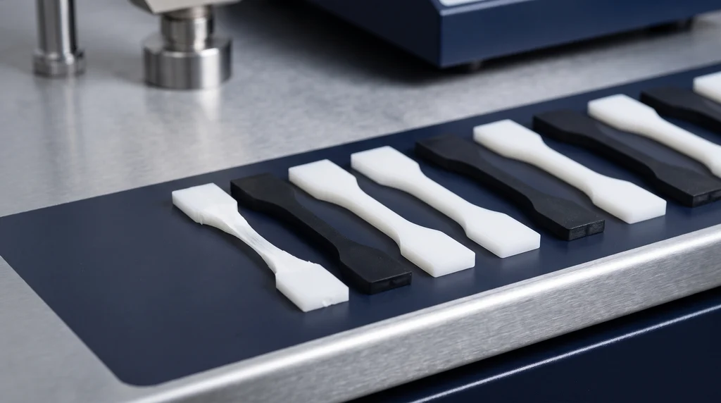
The D638 test specimen is a dog-bone: two wide ends, held in the grips, joined by large-radius fillets to a narrow straight section, where stress is highest and where fracture must occur. It can be injection molded, machined, or die-cut from sheet or plate. Injection molding orients the polymer chains and can give properties different from those of a machined specimen of the same material. The photo shows injection-molded dog-bone plastic test specimens: the wide ends go in the grips, and deformation takes place in the narrow middle section.
When to use each type
The choice depends on the material's rigidity class (rigid, semirigid or nonrigid), its thickness and the amount of sample available:
- Type I: preferred for rigid and semirigid plastics whenever material up to 7 mm thick is available. It is also the type indicated for reinforced composites, including laminates, except those with oriented high-modulus fibers, which follow D3039.
- Type II: recommended when the material does not break in the narrow section of Type I. The narrower gauge section (6 mm) concentrates stress where it should be.
- Type III: mandatory for any material more than 7 mm and up to 14 mm thick. Thicker sheet is machined down to 14 mm.
- Type IV: the type for nonrigid plastics up to 4 mm thick, and the one used when materials of different rigidity, such as a nonrigid and a semirigid, are to be compared directly with the same specimen.
- Type V: the miniature specimen, for when little material up to 4 mm thick is available or when many specimens must fit in a small space, such as an aging chamber.
Dimensions of the five types
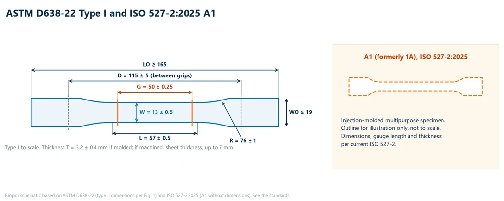
Two dimensions define how the specimen is used: the gauge length (G), the distance between the two knife edges of the extensometer, over which elongation is calculated; and the distance between grips (D), over which nominal strain is calculated when elongation is read from crosshead movement. The thickness of molded specimens is 3.2 ± 0.4 mm for all types; for machined specimens, it is the sheet's own thickness, within the range of the type. The diagram below shows the five types at the same scale, with the gauge length marked in orange: Type III is the largest, because it takes sheets up to 14 mm, and Type V fits inside the narrow section of Type I.
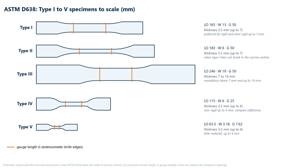
The table summarizes the main dimensions, in millimeters. The complete drawing, with tolerances, radii and end widths, is in the standard:
| Type | Gauge width × thickness | G and D (between grips) | Min. overall length |
|---|---|---|---|
| I | 13 × 3.2 (up to 7) | 50 and 115 | 165 |
| II | 6 × 3.2 (up to 7) | 50 and 135 | 183 |
| III | 19 × 7 to 14 | 50 and 115 | 246 |
| IV | 6 × 3.2 (up to 4) | 25 and 65 | 115 |
| V | 3.18 × 3.2 (up to 4) | 7.62 and 25.4 | 63.5 |
Source: Fig. 1 of ASTM D638-22. The distance between grips has a tolerance of ± 5 mm; for highly extensible polymers with self-tightening grips, the standard allows it to be adjusted.
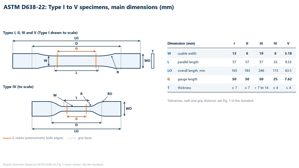
The next diagram shows where each dimension lies on the specimen: on the left, Type I (whose shape also applies to Types II, III and V) and Type IV, to scale, with the letter for each dimension; on the right, the main values for the five types. Note that Type IV is the only one with two radii in the fillet, R and RO. Tolerances, radii and distance between grips are in Fig. 1 of the standard.
Preparation, measurement and number of test specimens
D638 requires the width and thickness of each specimen to be measured with a resolution of 0.025 mm, at the center and within 5 mm of each end of the gauge length, with a micrometer per ASTM D5947. For injection-molded specimens, measuring one per sample is enough when the variation between them has already been shown to be less than 1%. The area used in calculations is the average initial cross-section within the gauge length.
Two recommendations from the standard for preparation (Note 10 and Section 6.5): transparent specimens can be examined in a polariscope to reveal residual stresses from molding or machining; and gauge marks are made with wax crayon or India ink, never scribed, because a scratch becomes a crack initiation point.
The minimum is five test specimens per sample of isotropic material. For anisotropic material, such as extruded sheet or laminate, it is ten: five with the axis parallel to the orientation direction and five perpendicular to it. A specimen that breaks at a flaw or outside the narrow section is discarded and replaced, unless the flaw is precisely the variable being studied.
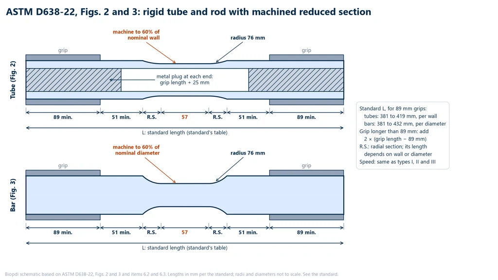
Rigid tubes and rods are not cut into dog-bones: D638 tests the tube or rod itself, with a reduced section machined at mid-length. The diagram below shows both preparations. The reduced section has a 57 mm straight portion, joined to the original diameter by 76 mm radii, and reduces the tube wall, or the rod diameter, to 60% of the nominal value, so that fracture occurs there and not in the grip. Note the minimum distances of 89 mm in the grip and 51 mm free on each side and, in the tube, the steel or brass plugs, as long as the grip plus 25 mm, which keep the clamping force from crushing the wall. The standard length of each piece comes from the standard's table, according to wall thickness or diameter.
Conditioning and test atmosphere
Plastics absorb moisture and their properties change with it; polyamide is the extreme case, with much lower stiffness when wet. That is why D638 requires specimens to be conditioned per ASTM D618-21, Procedure A, unless the contract or material specification requires otherwise: 23 °C and 50% relative humidity for at least 40 hours, for specimens up to 7 mm thick. Thicker specimens need longer, as defined in D618. The test is run in the same atmosphere as conditioning, within the D618 tolerances.
Forty hours do not bring a hygroscopic material to moisture equilibrium, which can take much longer; they standardize the state of the material so that different laboratories reach the same result.
Test speed
In D638, test speed is the rate of grip separation. The standard gives a table of fixed speeds by specimen type and rigidity class. The speed comes from the material specification or from agreement between the parties; when neither defines it, the rule is to use the lowest speed in the table that produces fracture within 0.5 to 5 minutes of testing. The table below summarizes the options, with tolerances:
| Class | Type | Speeds (mm/min) |
|---|---|---|
| Rigid and semirigid | I, II, III, rods and tubes | 5 (± 25%), 50 (± 10%), 500 (± 10%) |
| Rigid and semirigid | IV | 5 (± 25%), 50 (± 10%), 500 (± 10%) |
| Rigid and semirigid | V | 1, 10 and 100 (± 25%) |
| Nonrigid | III and IV | 50 (± 10%), 500 (± 10%) |
The rule calls for a preliminary test or experience with the material: a brittle material breaks in seconds at 50 mm/min and stays at 5; a polypropylene that stretches a lot would take more than 20 minutes at 5 mm/min and moves to 50. The modulus can be measured at the same speed as the other properties, as long as data acquisition is fast and fine enough to capture the initial portion of the curve.
Force and strain measurement
Force is measured by the machine's load cell, verified per ASTM E4, with an error of up to ±1% of the indicated force. In Brazil, the equivalent verification is per ABNT NBR ISO 7500-1:2023 (the Brazilian adoption of ISO 7500-1), whose Class 1 corresponds to this same ±1%. The load cell should be chosen for the test force: a polycarbonate Type I specimen breaks at around 2.6 kN, and measuring that with a 100 kN load cell wastes resolution.
Strain has requirements in three ranges, checked against the text of the standard:
- Modulus of elasticity: extensometer with a maximum error of 0.0002 mm/mm and automatic, continuous recording. A Class B-2 extensometer per ASTM E83-25 meets this. The standard prohibits using grip displacement to calculate modulus or elongation.
- Elongation at yield and small strains (up to about 20%): the same extensometer, or another of at least Class C per E83, with a fixed error of 0.001 strain or 1% of the reading, whichever is greater.
- Large strains (above 20%): measurement techniques with an error of up to 10% of the measured value, such as long-travel extensometers.
For referee testing, the extensometer is mounted over the entire gauge length (Section 5.2). The standard also sets two requirements for the machine itself (Sections 5.1.6 and 5.1.7): the elastic deformation of the frame, drive and grips must not exceed 1% of the strain measured between the gauge marks of the specimen, and the crosshead displacement indicator, from which nominal strain is derived, must have an error of up to 10% of the indicated value.
Why the crosshead is not suitable for measuring modulus in polymers is explained in the section on extensometers for polymers in the tensile test article. For D638, the consequence is what matters: when the specimen necks within the gauge length, strain is no longer uniform and the standard requires reporting nominal strain, the grip separation divided by the initial distance between grips, which has only qualitative value. For materials that elongate a lot, two tests can be run, one with the high-resolution extensometer for the modulus and another to fracture.
What is calculated and how
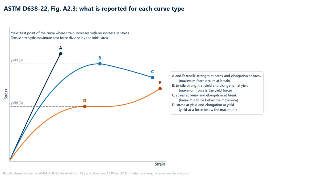
D638 works with engineering stresses: every force is divided by the average initial cross-sectional area of the gauge section, A0 = w × t, where w is the width and t the thickness. The yield point is the first point on the curve where strain increases with no increase in force. In ductile plastics it shows up as a peak followed by a drop. Tensile strength is the maximum force of the test divided by A0. The standard calls it tensile strength at yield or tensile strength at break, depending on where the maximum force occurred. The general concept is covered in ultimate tensile strength, and reading the curve is covered in stress-strain curve.
The diagram below, based on Fig. A2.3 of the standard, shows how these designations depend on the shape of the curve. When the maximum force occurs at yield (B), you report tensile strength at yield, and a break at a lower force (C) becomes stress at break. When the maximum force occurs at break (A and E), you report tensile strength at break, and a yield at a lower force (D) becomes stress at yield.
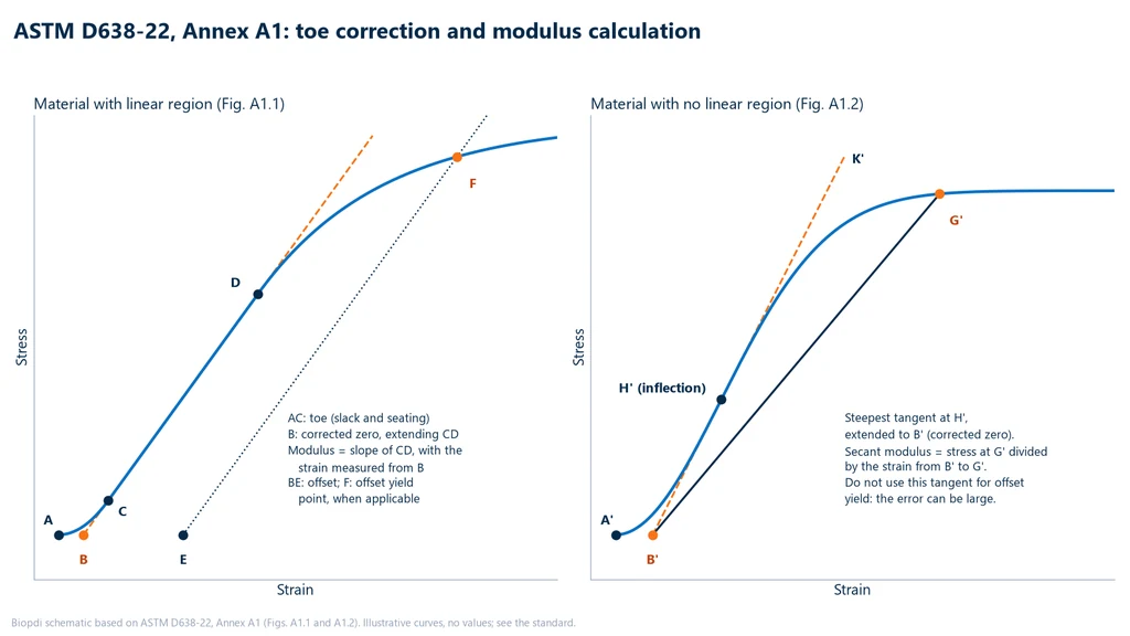
The modulus of elasticity is the slope of the initial linear region of the stress-strain curve. You extend the straight line of that region and divide the stress difference between two points on it by the strain difference. Many curves start out concave because of slack in the grips and specimen seating, and that initial region, the toe, is not a material property. Toe compensation (toe correction) extends the line of the linear region down to the strain axis and takes that intersection as the new zero. When there is no linear region, you calculate the secant modulus: the stress at a specified strain divided by that strain. The modulus concept is covered in modulus of elasticity, and elongation as a measure of ductility has its own article. The table brings the formulas together:
| Result | Formula | Note |
|---|---|---|
| Initial area | A0 = w × t | average of measurements in the gauge section, in mm² |
| Tensile strength | σ = Fmax / A0 | at yield or at break, in MPa |
| Stress at yield and at break | σy = Fy / A0; σb = Fb / A0 | reported when lower than the maximum |
| Elongation | ε = ΔL / G × 100 | from the extensometer, uniform strain |
| Nominal strain | εn = ΔD / D × 100 | from grip separation, when necking occurs |
| Modulus of elasticity | E = Δσ / Δε | linear region, with toe compensation |
| Secant modulus | Es = σ / ε | at a specified strain |
| Poisson's ratio | ν = −εtransverse / εaxial | optional; requires a transverse extensometer |
Annex A1 of the standard covers toe compensation in two cases. With a linear region, line CD extended to the axis gives the new zero B, from which all strains are measured, including the offset BE of an offset yield strength. Without a linear region, you draw the tangent of maximum slope at the inflection point H', which gives the corrected zero B', and the secant modulus is the slope of the line from B' to the chosen point G'. The standard warns that in this second case, using the tangent as the basis for an offset yield strength can lead to a large error. The diagram below shows both cases, with the points the standard names.
Stress and modulus results are reported to three significant figures. For each series, you calculate the mean and the estimated standard deviation, the latter to two significant figures. Poisson's ratio, when requested, follows Annex A3 of the standard: the test runs at 5 mm/min, after a preload below 5 N, with axial and transverse extensometers (or a biaxial one), up to at least 0.5% strain. Without a linear region, the calculation uses the interval between 0.05% and 0.25% axial strain. The annex has no precision data, so it is not suitable for referee testing.
What goes in the report
The D638 report identifies the material (type, manufacturer, code, form and history) and how the test specimens were prepared. It records the specimen type and dimensions, the conditioning, the laboratory atmosphere, the number of specimens (and their direction, if the material is anisotropic), the speed, the extensometer class, the mean and standard deviation of each result, the test date and the edition of the standard. The edition matters, and the test report should cite the revision used. From D638-14 to D638-22 the procedure did not change: according to the standard's own summary of changes, the terminology and the precision data changed.
Worked example: polycarbonate, Type I
A lab tests polycarbonate using injection-molded Type I specimens, with a measured width of 13.0 mm and thickness of 3.20 mm. In a preliminary test, the specimen broke at a grip separation of 92 mm. In the initial region, the 50 mm extensometer recorded 0.25 kN at ΔL = 0.150 mm and 0.65 kN at ΔL = 0.350 mm. The force at yield, which is the maximum of the test, was 2.60 kN, with ΔL = 3.025 mm on the extensometer. The force at break was 2.30 kN, at a grip separation of 92 mm.
- Speed. At 5 mm/min, the test would take 92 / 5 = 18.4 min, outside the 0.5 to 5 min window. At 50 mm/min, it takes 92 / 50 = 1.84 min, inside it. Speed: 50 mm/min. At that speed the modulus region goes by in under 1 second, and data acquisition has to keep up.
- Area: A0 = 13.0 × 3.20 = 41.6 mm².
- Stresses and strains in the linear region: σ1 = 250 / 41.6 = 6.01 MPa and σ2 = 650 / 41.6 = 15.63 MPa; ε1 = 0.150 / 50 = 0.0030 and ε2 = 0.350 / 50 = 0.0070.
- Modulus: E = (15.63 − 6.01) / (0.0070 − 0.0030) = 9.62 / 0.0040 = 2,404 MPa, reported as 2.40 GPa.
- Toe compensation: the line reaches zero stress at ε = 0.0030 − 6.01 / 2,404 = 0.0030 − 0.0025 = 0.0005, that is, 0.05%. This is the new strain zero.
- Yield: σy = 2,600 / 41.6 = 62.5 MPa. Since this is the highest force of the test, it is also the tensile strength, reported as tensile strength at yield. Elongation at yield is 3.025 / 50 × 100 = 6.05%, minus the 0.05% toe: 6.0%.
- Break: σb = 2,300 / 41.6 = 55.3 MPa. The polycarbonate necked in the gauge section, so elongation at break is reported as nominal strain: 92 / 115 × 100 = 80%.
- Machine: the maximum force of 2.6 kN uses just over half of a 5 kN load cell, and the 92 mm grip separation is small compared with the crosshead travel of a single-column machine.
The graphs below show the example. On the left is the initial region, with the toe, the two measured points and the tangent extended to the new zero. On the right is the full curve in nominal strain, with the yield peak, the cold drawing as the neck travels along the gauge section, and the break.
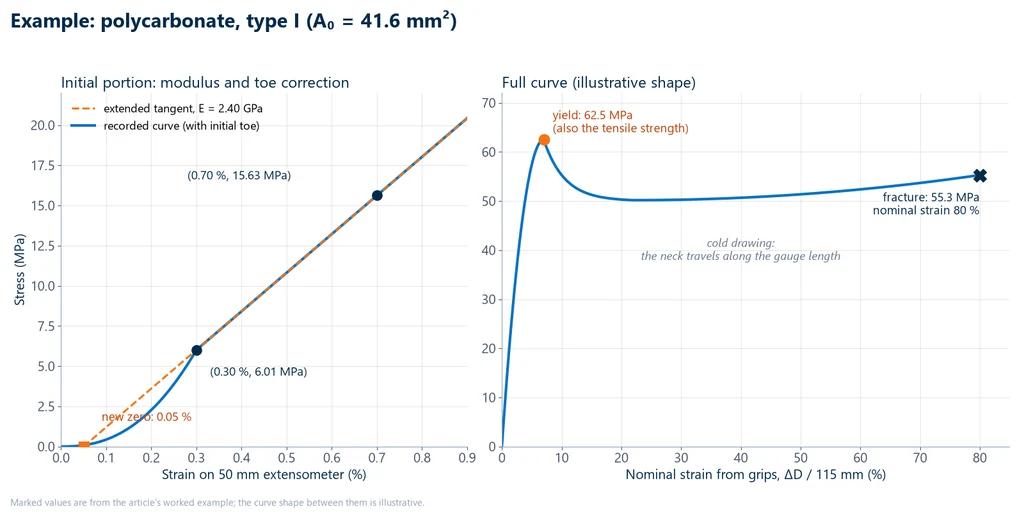
The modulus and yield stress fall within the typical range for polycarbonate, around 2.4 GPa and 60 to 70 MPa, which works as a sanity check. The propagating neck is covered in necking and cold drawing.
Type IV, nonrigid. A 6.0 × 3.0 mm Type IV specimen breaks at 0.33 kN after a grip separation of 390 mm. A0 = 6.0 × 3.0 = 18.0 mm² and σ = 330 / 18.0 = 18.3 MPa. For nonrigid plastics, the options are 50 and 500 mm/min. At 50 mm/min the test would take 390 / 50 = 7.8 min, outside the window. At 500 mm/min it takes 0.78 min, inside it. Speed: 500 mm/min, with a 2 kN load cell and a long-travel extensometer.
ASTM D638 vs. ISO 527-1 and ISO 527-2:2025
Outside the United States, the standard most often specified for the same test is ISO 527. Part 1 (2019) gives the general principles and calculations, and Part 2 gives the conditions for molding and extrusion plastics. ISO 527-2 got a new edition in 2025, which replaced the 2012 edition and renamed specimens 1A and 1B to A1 and A2, aligning them with ISO 20753, according to the official ISO page. A1 is the injection-molded multipurpose specimen, and A2 is the machined one. ISO 527-1:2019 was confirmed in 2025 and is marked for revision. In Brazil, plastics labs usually work with ISO itself or with ASTM.
The diagram below shows Type I with the dimensions from Fig. 1 of D638-22 and, next to it, A1 as an outline only, without dimensions. Take the A1 dimensions, gauge length and thickness from the current ISO 527-2.
The differences go beyond geometry. The most important one is the modulus. ISO measures it at 1 mm/min on A1 and A2 specimens and calculates it from the chord or a linear regression between 0.05% and 0.25% strain. D638 uses the slope of the linear region, usually at the same speed as the other properties. The table sums it up:
| Item | ASTM D638-22 | ISO 527-1:2019 and 527-2:2025 |
|---|---|---|
| Main specimen | Type I: 165 mm, 13 × 3.2 mm | A1 (formerly 1A): 10 × 4 mm narrow section; overall length per the current edition |
| Gauge length | 50 mm | 50 mm in the 1993 edition; check the value in the current edition |
| Other specimens | Types II to V | A2 (machined) and reduced-size specimens (the 2025 edition refers to ISO 20753) |
| Modulus test speed | same as the other properties (5 mm/min or more for Type I) | 1 mm/min |
| Modulus calculation | slope of the linear region, with toe compensation | chord or regression between 0.05% and 0.25% |
| Extensometer for modulus | ASTM E83 Class B-2 | 1% of reading accuracy in the 1996 edition; check the class required in the current edition |
| Atmosphere | ASTM D618 (23 °C, 50%, 40 h) | ISO 291 (23 °C, 50%) |
A resin tested to both standards gives close but not identical numbers, and you cannot convert one into the other by calculation: molding thickness, orientation and speed all change together. A datasheet produced to ISO cannot be compared with a specification written to ASTM without testing to the required standard.
Common mistakes when applying ASTM D638
The mistakes below show up both in the lab and on web pages that explain the standard, and each one has a straightforward fix:
- Modulus from crosshead displacement. It includes slack, seating and deformation of the specimen ends and the grips, and gives a low modulus. The standard requires a Class B-2 extensometer.
- One fixed speed for everything. Using 50 mm/min for every rigid plastic ignores the 0.5 to 5 minute rule. A brittle material at that speed breaks in seconds.
- Slippage in the grips. It shows up as a step or a false plateau on the curve. The fix is a grip suited to the material, properly aligned, with enough pressure; too much clamping crushes the specimen end and causes failure at the grip faces.
- Accepting a break outside the narrow section. The result is discarded and the test repeated. If Type I keeps breaking at the ends, the standard's prescribed route is Type II.
- Wrong type for the thickness. Above 7 mm, Type III is mandatory. Below 1.0 mm, ASTM D882 is the preferred method; D638 only allows that thickness with a specimen die-cut using the Type IV die, and the test report must say so.
- Skipping conditioning or testing in a room without temperature and humidity control.
- Measuring thickness poorly. In the example, an actual thickness of 3.10 mm entered as 3.20 mm would give 62.5 MPa instead of 2,600 / (13.0 × 3.10) = 64.5 MPa: 3.1% below the true value.
- Reporting extensometer elongation after necking. With non-uniform strain, the result is the nominal strain.
- Citing D638-14 as current or ISO 527-2:2012, which was withdrawn in 2025.
Equipment for ASTM D638 testing
The test calls for a universal testing machine (UTM) with constant crosshead speed, from 1 to 500 mm/min to cover every row of the speed table, a load cell sized to the specimen force, grips that hold the plastic without crushing it or letting it slip, and extensometers for both strain ranges. In the Biopdi M2 line, the single-column MBIOI-10-M2 machine is offered in 2, 5 or 10 kN, with speeds from 0.02 to 500 mm/min and 890 mm of crosshead travel, and the extended-column version reaches 1,290 mm of travel for materials that elongate by hundreds of percent. The load cell is class 1 according to ISO 7500-1 (ABNT NBR ISO 7500-1:2023 in Brazil), and the BioLab software plots the curve and calculates strength, elongation and modulus. The panel below shows the machine, the role of each part in ASTM D638 testing and the accessories used.
The universal testing machine in tensile testing of plastics
The M2 line includes single-column models, from 200 N to 10 kN, which cover most D638 specimens, and dual-column models, from 5 kN to 1,000 kN, for thick sheets and composites. Each part of the machine has a role in the test:

- Moving crosshead separates the grips at 5, 50 or 500 mm/min
- Load cell from 2 to 10 kN, class 1
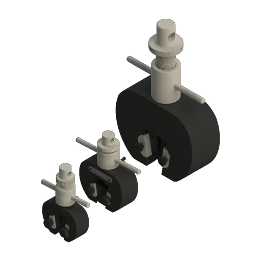
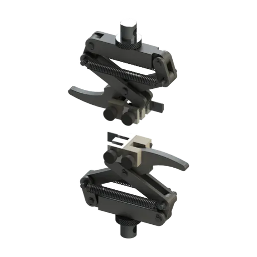
- Grips wedge or lever type, hold the ends of the dogbone specimen
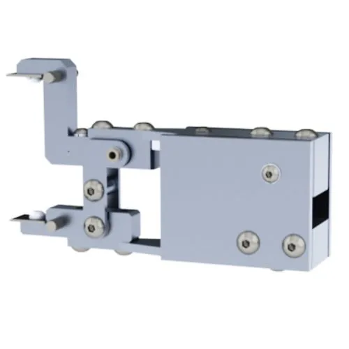
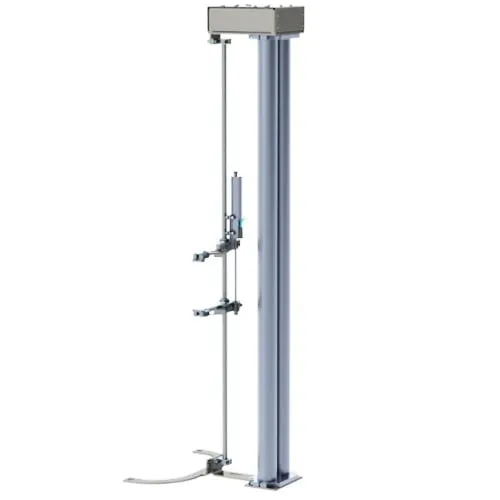
- Extensometer 50 or 25 mm for the modulus; long-travel up to fracture
- BioLab software modulus, yield, break, mean and standard deviation
- Control panel and emergency stop positions and stops the test
Accessories for tensile testing of plastics
The grips and extensometers below are mounted on the same machine, depending on the specimen type and the strain range:
Model selection starts from the maximum expected force, F ≈ σ × A0, and from the elongation at break. The table below shows the model for each application:
| Test specimen | Typical force | Biopdi model |
|---|---|---|
| Types I, II, IV and V in rigid and semirigid plastics | up to about 5 kN | MBIOI-10-M2 (2, 5 or 10 kN) |
| Type IV nonrigid, elongation of hundreds of percent | hundreds of N | Extended-column MBIOI-10-M2 |
| Type III for thick sheet, composites | above 10 kN | MBIOII-50-M2 (5 to 50 kN) |
A 19 × 14 mm type III specimen in a 60 MPa plastic requires 60 × 266 = 15,960 N, close to 16 kN, beyond the single-column range. The same machine performs flexural testing of plastics to ASTM D790, the subject of the ASTM D790 guide, and polymer tests such as those described in biodegradable polymers. How the machine works internally is covered in universal testing machine, and for a proposal configured for your laboratory, request a quote.
Standards cited
The table lists the standards cited in this guide with the current edition, checked on September 30, 2026 on each organization's official page:
| Standard | Subject | Edition |
|---|---|---|
| ASTM D638 | tensile properties of plastics, up to 14 mm | D638-22 |
| ASTM D882 | tensile properties of thin plastic sheeting and films, less than 1.0 mm | D882-26 |
| ASTM D618 | conditioning of plastics | D618-21 |
| ASTM E83 | extensometer classes | E83-25 |
| ASTM E4 | force verification of testing machines | E4-24 |
| ASTM D3039/D3039M | tensile properties of polymer matrix composites | D3039/D3039M-17 (reapproved 2025) |
| ASTM D412 | tension testing of rubber and thermoplastic elastomers | D412-16 (reapproved 2021) |
| ISO 527-1 | tensile properties of plastics: general principles | 2019 (under revision) |
| ISO 527-2 | tensile properties of moulding and extrusion plastics | 2025 |
| ISO 527-3 | tensile properties of films and sheets | 2018 |
| ISO 291 | standard atmospheres for conditioning and testing of plastics | 2008 (confirmed 2021) |
| ABNT NBR ISO 7500-1 | force verification of testing machines (Brazilian adoption of ISO 7500-1) | 2023 |
ASTM D790, which often shows up in searches alongside D638, covers flexural testing of plastics, not tensile testing: the bar rests on two supports and is loaded at midspan, as explained in flexural test.
Other tests and technical references
Tests performed on the Biopdi universal testing machine



















Related technical references
ASTM D412 and ISO 37: rubber tensile test, test specimens, speed and calculations
ASTM D412 and ISO 37 rubber tensile test: dumbbell or ring at 500 mm/min, tensile strength, elongation at break and stress at 100% and 300%.
ASTM D882: tensile testing of plastic films, strip specimen, test speed and secant modulus
ASTM D882-26 covers tensile testing of plastic films under 1.0 mm thick in 5 to 25.4 mm strips: speed, grips, secant modulus, example and D638 differences.
ASTM D3039: tensile testing of composites, tabbed test specimens, chord modulus and failure modes
ASTM D3039 tensile test of polymer matrix composites: tabbed specimens, chord modulus from 1,000 to 3,000 µε and the failure code.
Frequently asked questions
What is ASTM D638?
It is the ASTM International test method for the tensile properties of unreinforced and reinforced plastics up to 14 mm thick. It uses dogbone-shaped test specimens, types I to V, and yields tensile strength, stress at yield and at break, elongation and modulus of elasticity. The current edition is D638-22.
Which ASTM standard covers tensile testing?
It depends on the material. Metals follow ASTM E8/E8M; rigid, semirigid and nonrigid plastics up to 14 mm, D638; films less than 1.0 mm thick, D882; fiber-reinforced polymer matrix composites, D3039/D3039M; rubbers and thermoplastic elastomers, D412.
Which standard covers tensile testing of polymers?
The two most widely used are ASTM D638-22 and ISO 527, with part 1 from 2019 and part 2 from 2025. Thin films and sheets have their own standards: ASTM D882-26 or ISO 527-3.
What are the dimensions of the ASTM D638 type I specimen?
Minimum overall length of 165 mm, narrow section 57 mm long and 13 mm wide, 50 mm gauge length, 115 mm distance between grips and a thickness of 3.2 ± 0.4 mm when molded. It is the preferred specimen for rigid and semirigid plastics up to 7 mm thick.
What is the test speed in ASTM D638?
The speed given in the material specification; without one, the lowest speed in the standard's table that produces rupture within 0.5 to 5 minutes. For types I to IV, the options are 5, 50 and 500 mm/min (only 50 and 500 for nonrigid plastics); for type V, 1, 10 and 100 mm/min.
How many test specimens does ASTM D638 require?
At least five per sample for isotropic materials. For anisotropic materials, ten are required: five parallel and five perpendicular to the direction of orientation. A specimen that breaks outside the narrow section or at a flaw is replaced.
Do I need an extensometer for ASTM D638 testing?
For the modulus of elasticity, yes: the system must have a maximum error of 0.0002 mm/mm, which an ASTM E83 class B-2 extensometer meets, and grip displacement cannot be used. Above 20% strain, the standard accepts wide-range measurement with an error of up to 10% of the measured value.
Do ASTM D638 and ISO 527 give the same result?
Not necessarily. ASTM itself states that the two cover the same subject with different technical content: the specimen (type I at 13 × 3.2 mm versus A1 at 10 × 4 mm), the modulus test speed (1 mm/min in ISO) and the modulus calculation all differ. Test reports to the two standards are not interchangeable.
What is the difference between ASTM D638 and ASTM D882?
D882-26 covers sheeting and films less than 1.0 mm thick, with a strip specimen. D638 covers plastics up to 14 mm thick, with a dogbone specimen, and points to D882 as the preferred method below 1.0 mm. The practical boundary between the two is a thickness of 1.0 mm.
Where can I find ASTM D638 as a PDF?
The standard is sold by ASTM at store.astm.org. The free PDFs circulating online are usually unauthorized copies of the old D638-14 edition, and they are not valid as a reference for a test report, which must cite the current edition, D638-22.