
The axial-torsion test applies axial force (tension or compression) and torque to the same test specimen, together or one at a time, in-phase or out-of-phase. The force produces the normal stress σ = F/A, the torque produces the shear stress τ = T·r/J, and the two combine in the von Mises equivalent stress, √(σ² + 3τ²), not by direct addition.
The test is also called the combined tension and torsion test, or axial torsion testing. The fatigue reference is ASTM E2207-15(2021), which uses a thin-walled tubular specimen under strain control. In this guide you will find what the test measures, the stresses in the specimen and the derivation of the torsion formula, the von Mises and Tresca criteria, five worked examples, the difference between in-phase and out-of-phase loading, the table of standards with editions checked on October 13, 2026, the step-by-step procedure, the machine and the most common mistakes.
What is the axial-torsion test
The axial-torsion test is the mechanical test that loads the specimen on two axes at the same time: the linear axis, with tensile or compressive force, and the rotary axis, with torque about the same centerline. The result is a stress state that neither test produces on its own: the specimen surface carries normal stress and shear stress simultaneously. ASTM E2207 describes this loading as essentially biaxial and notes that, with thin-walled tubes, it explores two of the four quadrants of principal stress or strain space.
The pure torsion test applies torque only and measures torque, angle of twist and the shear modulus G; the tensile test applies axial force only and measures yield, strength and elongation. The axial-torsion test does not replace either of them: it exists to answer what happens when both loads act together, as in a tightened bolt, a drive shaft carrying axial load or a bone implant. Torsion, in this context, is the rotation of one cross-section relative to another caused by a moment about the axis of the part; the force that twists is the torque, measured in N·m.
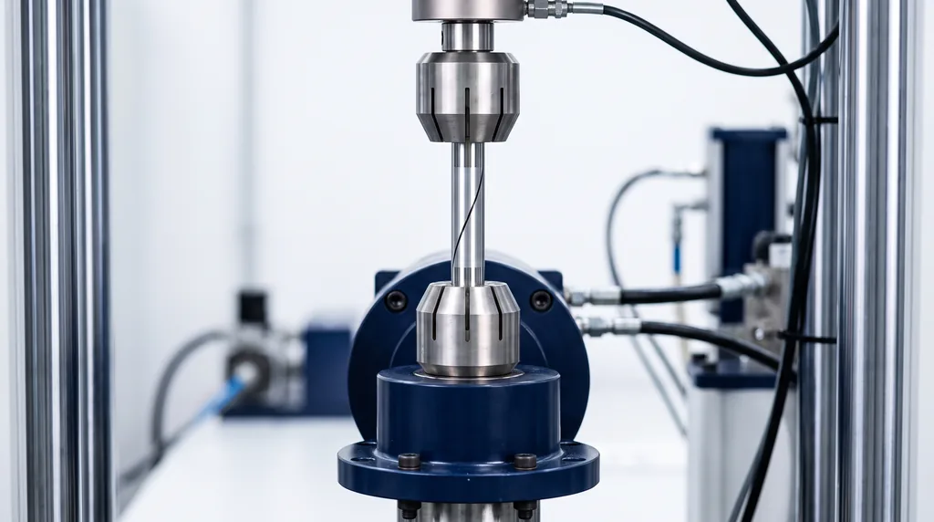
In the photo, a metal specimen is held between two collet grips aligned on the same vertical axis, with the lower one mounted on a torsion head. Before the test, a straight line was scribed on the specimen, parallel to the axis. With torque added to the axial load, the line turned into a helix: this is the shear strain produced by the torque, visible to the naked eye.
Axial testing: tension, compression and pull-out
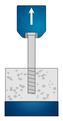
An axial test is any test in which the force acts along the specimen axis, and the axial stress is the force divided by the cross-sectional area: σ = F/A. With F in newtons and A in mm², σ comes out in MPa (N/mm²); in US customary units, in psi (1 MPa = 145.04 psi). The most common axial tests are tension, compression and pull-out, which measures the force needed to extract a fastener, an anchor or a screw from the material it is fixed in. Searches for "axial load test" and "axial force resistance testing" refer to this family. The axial-torsion test adds a second channel, torque, to the axial test.
Types of axial-torsion test
Axial-torsion tests are classified by four criteria. By load regime, there is the static test (load increasing to yield or fracture, or held at a proof value) and the cyclic fatigue test. By order, there is the simultaneous test, in which both channels work at the same time, and the sequential test, in which one load is applied first and then the other. By the relationship between channels, the simultaneous test can be in-phase (proportional) or out-of-phase (non-proportional). By objective, there is the material test, on a standard specimen, and the functional test, on a finished part such as a bolt, a steering column or a medical connector. Temperature also matters: E2207 covers tests at room and elevated temperature, with a furnace or chamber around the specimen.
The test has clear advantages: it reproduces the service stress state, it allows the yield surface of the material to be mapped with a single specimen type and, in fatigue, it measures the effect of rotating principal directions, which no uniaxial test shows. The disadvantages are just as clear: the machine is more expensive, because it needs two actuators and a two-channel load cell; the tubular specimen is costly to machine and can buckle in compression; and the result depends heavily on alignment and strain measurement, as the section on mistakes shows.
Why combine tension and torsion
Combining tension and torsion is necessary because many parts carry both loads at the same time, and the material yields or cracks under this combined state earlier than the separate tests would indicate. The Smithers laboratory sums up the reason: an axial test alone is not enough to evaluate a part that also carries rotational load. The most common example is on every workbench: the bolt. When it is tightened, the wrench applies torque, and the tightening itself creates tension in the bolt shank; during assembly, both loads coexist.
The table lists examples of parts in which the combination appears, and which load comes from each side:
| Part | Axial load | Torsional load |
|---|---|---|
| Bolt during tightening | tension in the shank from preload | tightening torque and thread friction |
| Drive shaft and axle shaft | axial load from helical gears and joints | torque transmitted by the engine |
| Steering column | compression or tension on impact and during adjustment | steering wheel torque |
| Cable and wire in service | tension from weight or installation tension | twist imposed during winding |
| Bone screw and orthopedic implant | pull-out and bone load | insertion and removal torque |
| Turbine blade and drill pipe | centrifugal force or string weight | torsion from fluid pressure or rotation |
Instron lists hip implants and turbine blades among the applications of its axial-torsion systems; Smithers lists radiator caps, steering columns, ball joints and bone screws. In all of them, the goal is to know the response of the part or material to the combined state, which Example 3 in this article shows to be more severe than either load alone.
Stresses in the specimen under tension and torsion
In a circular specimen under tension and torsion, each point on the surface has a normal stress σ in the axial direction and a shear stress τ in the plane of the cross-section, and the two are calculated separately before being combined. The formulas in this section come from mechanics of materials (Hibbeler, Beer and Johnston, and the Boston University course on mechanics of slender structures) and are valid while the material is in the elastic range.
Axial stress
The axial stress is σ = F/A. In the tube, the area is the annulus: A = (π/4)·(do² − di²), where do is the outer diameter and di the inner diameter. The stress is uniform over the section, positive in tension and negative in compression. It is the same as in the tensile test, and the corresponding strain is ε = ΔL/L0, measured over the gauge length L0.
Torsional shear stress: where τ = T·r/J comes from
The torsion formula follows from four steps, in the classic derivation for a circular bar:
- Plane sections remain plane. In a circular bar, each cross-section rotates like a rigid disk, without warping. This assumption only holds for circular sections, solid or hollow.
- Geometry. If the section at position L has rotated by an angle φ relative to the fixed section, a straight line on the surface becomes a helix, and the shear strain at a distance r from the center is γ = r·φ/L. It is zero at the center and maximum at the surface.
- Material. In the elastic range, τ = G·γ (Hooke's law in shear), where G is the shear modulus. Therefore τ = G·r·φ/L, also linear in r.
- Equilibrium. The sum of the moments of the stresses over the section is the torque: T = ∫τ·r·dA = (G·φ/L)·∫r²·dA = (G·φ/L)·J, where J is the polar moment of inertia.
Combining steps 3 and 4 gives the two torsion equations: τ = T·r/J and φ = T·L/(G·J). For a tube, J = (π/32)·(do⁴ − di⁴); for a solid bar, J = π·d⁴/32, which gives τmax = 16·T/(π·d³) at the surface. Shear stress is the only type of stress that pure torsion produces on the cross-section; what changes with tension is how it combines with σ. Torsional strength is the maximum torque the part can withstand, or the corresponding shear stress; in ASTM F543, for bone screws, the parameters are maximum torque, torsional yield strength and breaking angle.
Thin-walled tube: why the test uses a tube
In a solid bar, τ goes from zero at the center to a maximum at the surface. When the surface yields, the core is still elastic, and the formula τ = T·r/J stops being valid without the test showing the exact moment. In a thin-walled tube, almost all the material is at the same distance from the center, and τ is practically uniform through the thickness. The mean stress is calculated as:
τ ≈ T / (2π·rm²·t), where rm is the mean radius and t the wall thickness.
This is why ASTM E2207 requires a tubular specimen: the standard notes that, in the tube, the stress state is constant over the gauge section and well known, which makes axial-torsion loading more convenient than in-plane biaxial loading. In Example 1, the thin-wall approximation gives 90.3 MPa, against 89.6 MPa from the exact formula at the mean radius (a difference of 0.8%) and 97.4 MPa at the outer radius. The price of the tube is buckling: in compression or under high torsion, the thin wall can wrinkle before the material yields.
Axial, lateral and shear strain
Three strains appear in the test. The axial strain, ε = ΔL/L0, is the change in length in the direction of the force. The lateral (or transverse) strain is the change in diameter: in tension, the diameter decreases. The ratio between the two, with the sign reversed, is Poisson's ratio: ν = −εlateral/εaxial, close to 0.3 for metals in the elastic range. The shear strain, γ = r·φ/L, is the change in angle between two lines that were perpendicular, and it is what turns the straight line in the photo into a helix.
The elastic constants are related by G = E / [2·(1 + ν)]. For steel, with E = 200 GPa and ν = 0.3, G ≈ 77 GPa (Biopdi calculation); this is why the same test that measures the modulus of elasticity on the axial channel can measure G on the torsional channel. ASTM E143-20 is the standard for measuring G in torsion at room temperature.
Principal stresses and Mohr's circle
With σ and τ at the same point, there are two directions in which there is only normal stress: the principal directions. The stresses in these directions are:
σ1,2 = σ/2 ± √[(σ/2)² + τ²]
The direction of σ1 is inclined to the axis by an angle θ given by tan 2θ = 2τ/σ. In pure tension, θ = 0; in pure torsion, θ = 45°, which is why twisted chalk breaks along a 45° helix. In the combination, the angle lies between the two: a brittle material under tension and torsion breaks along a tighter helix than in pure torsion. The diagram below shows the tube from Example 1 with the surface element enlarged, on the left, and the corresponding Mohr's circle, on the right. Point X represents the face perpendicular to the axis (σ and τ), point Y the face parallel to the axis (zero and −τ), and the diameter XY crosses the horizontal axis at the principal stresses.
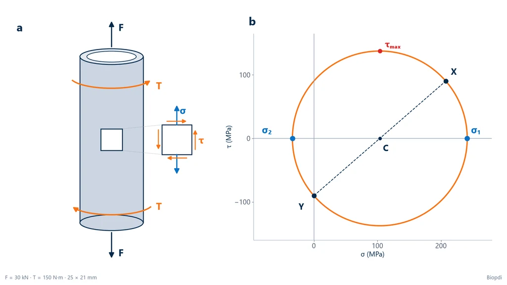
The circle shows two things the formulas hide. First, tension combined with torsion creates a compressive principal stress (negative σ2), even though no compressive load was applied. Second, the maximum shear stress, the radius of the circle, is greater than the applied τ: 137.6 MPa versus 90.3 MPa in the example. The table summarizes the formulas in this section (for conversion, 1 N·m = 8.851 lbf·in and 1 kN = 224.8 lbf):
| Quantity | Formula | Units |
|---|---|---|
| Axial stress | σ = F / A | N, mm², MPa |
| Tube area | A = (π/4)·(do² − di²) | mm² |
| Polar moment of the tube | J = (π/32)·(do⁴ − di⁴) | mm⁴ |
| Torsional shear stress | τ = T·r / J | N·mm, mm, MPa |
| Shear stress, thin wall | τ ≈ T / (2π·rm²·t) | MPa |
| Angle of twist | φ = T·L / (G·J) | rad |
| Shear strain | γ = r·φ / L | dimensionless |
| Shear modulus | G = E / [2·(1 + ν)] | GPa |
| Principal stresses | σ1,2 = σ/2 ± √[(σ/2)² + τ²] | MPa |
| Von Mises | σvM = √(σ² + 3τ²) | MPa |
| Tresca | σTr = √(σ² + 4τ²) = σ1 − σ2 | MPa |
Von Mises, Tresca and the yield surface
Under combined tension and torsion, the material yields when the equivalent stress reaches the tensile yield strength: by the von Mises criterion, σvM = √(σ² + 3τ²) = σy; by the Tresca criterion, √(σ² + 4τ²) = σy. Both criteria reduce the combined stress state to a single number that can be compared with the yield strength measured in the tensile test. Von Mises comes from distortion energy. Tresca comes from the maximum shear stress, which is the radius of Mohr's circle.
Adding σ and τ directly is wrong, because they act in different directions and combine as squares. In pure torsion (σ = 0), the criteria give the shear yield strength: τy = σy/√3 ≈ 0.577·σy by von Mises and τy = 0.5·σy by Tresca, a difference of about 15%. Which one better describes a given material is an experimental question, and the axial-torsion test is the test that answers it. Taylor and Quinney tested copper, aluminum and mild steel tubes under combined tension and torsion (Philosophical Transactions of the Royal Society A, 1932) and found that the yield points fell closer to von Mises than to Tresca.
The chart below shows the two yield surfaces in the σ × τ plane for a material with σy = 350 MPa, a hypothetical value used in the examples. Every stress state inside the curve is elastic; on the curve, the material yields. The Tresca ellipse lies inside the von Mises ellipse: the two coincide in pure tension (σ = ±350 MPa) and are furthest apart in pure torsion (points A and B). Point P is the stress state of Example 1. The dotted line from the origin through P is proportional loading, in which force and torque increase together, and it crosses the ellipse where the tube would yield. Points C and D show the allowable shear stress with the 30 kN tensile load applied (Example 3).
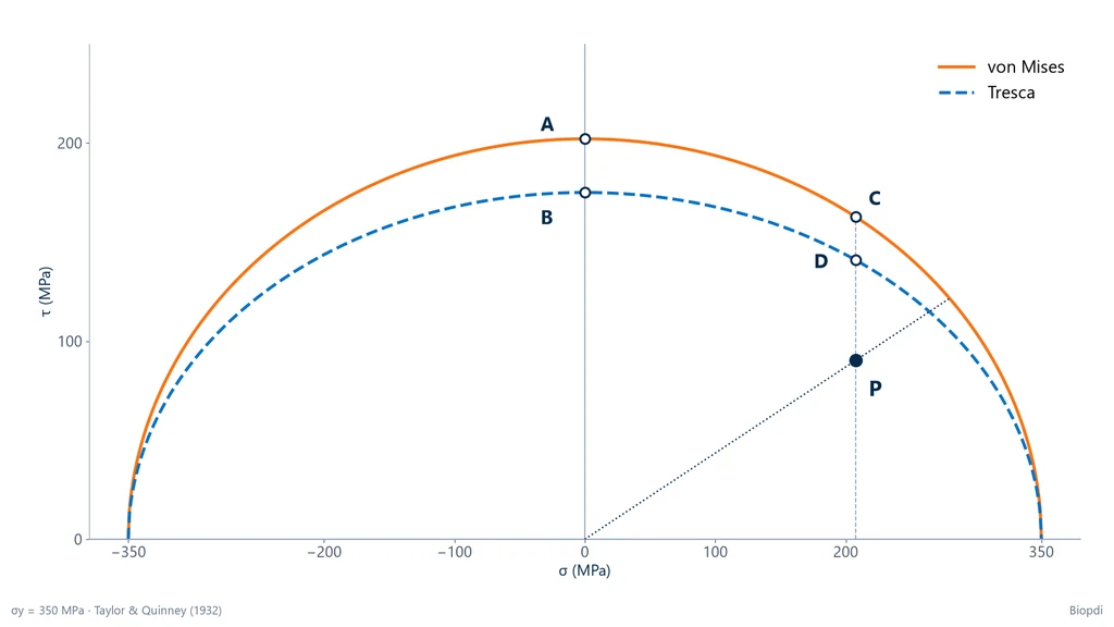
In design, the usual choice is von Mises for ductile metals in general, because it best represents the average of the data, and Tresca when a margin on the safe side is wanted, because it always gives the higher equivalent stress. Both criteria deal with yielding. Brittle fracture and fatigue call for other criteria, discussed below.
Worked examples of tension and torsion
The examples use a steel tube with an outside diameter of 25 mm and an inside diameter of 21 mm (wall thickness t = 2 mm, mean radius rm = 11.5 mm). The yield strength σy = 350 MPa is hypothetical, chosen only for the exercises. The calculations are Biopdi's, rechecked on October 13, 2026.
1. Stresses, von Mises and Tresca. F = 30 kN (6,744 lbf) and T = 150 N·m (1,328 lbf·in).
- Area: A = (π/4)·(25² − 21²) = (π/4)·184 = 144.5 mm². Axial stress: σ = 30,000 / 144.5 = 207.6 MPa (about 30,100 psi).
- Shear stress from thin-wall theory: 2π·11.5²·2 = 1,661.9 mm³, and τ = 150,000 / 1,661.9 = 90.3 MPa. Check with the exact formula: J = (π/32)·(25⁴ − 21⁴) = 19,256 mm⁴; τ at the outer radius = 150,000 × 12.5 / 19,256 = 97.4 MPa; at the mean radius, 89.6 MPa.
- Principal stresses: center 207.6/2 = 103.8 MPa; radius √(103.8² + 90.3²) = 137.6 MPa; σ1 = 241.3 MPa and σ2 = −33.8 MPa. The direction of σ1 is at 20.5° to the axis (tan 2θ = 180.5 / 207.6).
- Von Mises: σvM = √(207.6² + 3 × 90.3²) = 259.9 MPa (about 37,700 psi). Tresca: σTr = √(207.6² + 4 × 90.3²) = 275.1 MPa, equal to σ1 − σ2.
- Safety factor against yielding: 350 / 259.9 = 1.35 (von Mises) and 350 / 275.1 = 1.27 (Tresca).
2. Yield torque in pure torsion. Same tube, no axial force. By von Mises, τy = 350 / √3 = 202.1 MPa, and Ty = 202.1 × 1,661.9 = 335.8 N·m. By Tresca, τy = 175.0 MPa and Ty = 290.8 N·m. These are points A and B on the chart.
3. How much torque fits with 30 kN applied. With σ fixed at 207.6 MPa, the shear stress that causes yielding is, by von Mises, τ = √[(350² − 207.6²)/3] = 162.7 MPa, and the torque is T = 162.7 × 1,661.9 = 270.4 N·m. By Tresca, τ = √[(350² − 207.6²)/4] = 140.9 MPa and T = 234.2 N·m. With both criteria, the allowable torque dropped 19.5% compared with pure torsion. This is the engineering message of the test: tension uses up part of the torsional capacity, and a part qualified only in torsion has its allowable torque overestimated if it works under tension. The force that would make the tube yield with no torque is σy·A = 350 × 144.5 = 50.6 kN.
4. Setting up a strain-controlled test. Gauge length Lg = 25 mm. Target: axial amplitude εa = 0.40% and shear amplitude γa = √3 × 0.40% = 0.693%, so that both components contribute equally to the von Mises equivalent strain.
- Equivalent strain: εeq = √(εa² + γa²/3) = √(0.16 + 0.16) = 0.566%.
- Axial displacement over the gauge length: 0.0040 × 25 = 0.10 mm.
- Rotation over the gauge length, at the mean radius: θ = γ·Lg/rm = 0.00693 × 25 / 11.5 = 0.0151 rad = 0.86°.
A tenth of a millimeter and less than one degree: these values are of the same order as the backlash and elastic deformation of the grips and frame. That is why, in a test like this, strain is measured with an extensometer on the gauge section, not from actuator displacement.
5. Order of magnitude in a small screw. Solid bar 4 mm in diameter with T = 2 N·m and F = 500 N. Shear stress at the surface: τ = 16 × 2,000 / (π × 4³) = 159.2 MPa. Axial stress: σ = 500 / 12.57 = 39.8 MPa. Von Mises: √(39.8² + 3 × 159.2²) = 278.5 MPa. Here torsion dominates: removing the axial force would change σvM by about 1% (from 278.5 to 275.7 MPa). The values are illustrative and are not requirements of any screw or bolt standard.
The table summarizes the results of the examples:
| Example | Load | Result |
|---|---|---|
| 1. 25 × 21 mm tube | 30 kN and 150 N·m | σ = 207.6; τ = 90.3; σvM = 259.9; σTr = 275.1 MPa |
| 2. Pure torsion | torque only | Ty = 335.8 N·m (vM) and 290.8 N·m (Tresca) |
| 3. Torsion with 30 kN | torque with fixed tension | Ty = 270.4 N·m (vM) and 234.2 N·m (Tresca), 19.5% lower |
| 4. Strain control | εa = 0.40%; γa = 0.693% | εeq = 0.566%; 0.10 mm and 0.86° over 25 mm |
| 5. 4 mm bar | 500 N and 2 N·m | τ = 159.2; σ = 39.8; σvM = 278.5 MPa |
In-phase and out-of-phase loading
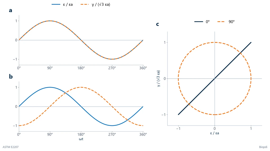
In in-phase loading, axial strain and shear strain peak at the same instant and the principal directions stay fixed; in out-of-phase loading, the peaks alternate and the principal directions rotate during the cycle. In-phase loading is also called proportional loading, because the ratio between the two channels is constant; out-of-phase loading is non-proportional. The most studied phase shift is 90°, where shear strain is at its maximum when axial strain passes through zero, and vice versa.
The chart below shows the two paths, with the strains divided by the amplitudes of Example 4. In (a), the axial and shear waves coincide; in (b), the shear wave lags by 90°. In the plane of the two strains, the 90° path is a circle: the equivalent strain stays constant throughout the cycle, while the direction in which it acts makes a full turn, as panel (c) shows.
The rotation of the principal directions has measured consequences. In a NASA study of type 316 stainless steel tubes at room temperature, out-of-phase tests showed shorter fatigue lives and more cyclic hardening than in-phase tests (Bonacuse and Kalluri, NASA, 1990). The physical reason is that, out of phase, the maximum shear sweeps through all planes of the material and activates more slip systems. Equivalent stress or strain criteria, which work reasonably well in phase, do not capture this effect. That is why multiaxial fatigue uses critical-plane models, such as those of Brown and Miller (1973) and Fatemi and Socie (1988), which evaluate strain on the most heavily loaded plane.
A sequential test is not an in-phase test. Applying the tensile load, holding it and then applying the torque produces a stepped path with a different hardening history. In a material that work hardens, the order of the loads changes the result, and the report must state which path was used.
Axial-torsional fatigue and ASTM E2207
ASTM E2207-15(2021) is the standard practice for strain-controlled axial-torsional fatigue testing of thin-walled tubular specimens, under axial, torsional or combined loading, in phase or out of phase. The standard is active (checked in the ASTM store on October 13, 2026), under subcommittee E08.05, and covers tests at room or elevated temperature. It is neither a static test method nor a component test: it generates material data for predicting the fatigue life of parts under multiaxial loading.
Its scope has limits that must be respected when specifying the test:
- Strain control, not force or torque control, on both channels.
- Zero mean strain (fully reversed loading) on both channels.
- Same frequency on the axial and torsional waveforms; the phase shift may vary, the frequency may not.
- Thin-walled tubular specimen of circular cross section, so that σ and τ are uniform over the gauge section.
- Homogeneous materials; the standard does not apply to components or structural members.
The last point is often misunderstood. Bone screws, implants, shafts and connectors are components: their testing follows the product standard, not E2207, even when the machine is the same. E2207 characterizes the material the part is made of.
In fatigue, the von Mises equivalent strain used in the literature for tubes under tension and torsion is εeq = √(ε² + γ²/3), the same as in Example 4. The typical result of the test is the curve of εeq amplitude versus number of cycles to failure, compared between in-phase and out-of-phase paths. Uniaxial fatigue, with the same strain-life reasoning, is covered in the article on fatigue testing.
For torsion-only fatigue, the standard is a different one: ISO 1352:2021 covers torque-controlled fatigue at constant amplitude in the nominally elastic range, on circular or tubular specimens, and excludes low-cycle testing under angle control. It replaced the 2011 edition, which has been withdrawn.
Axial-torsion test standards
There is no general axial-torsion test standard: ASTM E2207 covers material fatigue in tubes, and product tests involving tension and torsion are spread across standards for medical devices, wire and fasteners. The table lists the main ones, with edition and status checked in the ASTM store and the ISO catalog on October 13, 2026, and shows whether the standard combines the two loads or treats them in separate tests:
| Standard and edition | Scope | Tension and torsion |
|---|---|---|
| ASTM E2207-15(2021) | strain-controlled axial-torsional fatigue, thin-walled tube | combined, in phase and out of phase |
| ISO 1352:2021 | torque-controlled fatigue of metals | torsion only |
| ASTM E143-20 | shear modulus at room temperature | torsion only |
| ASTM F543-23 | metallic bone screws: torsion, insertion torque, pull-out | separate, in different annexes |
| ASTM F1717-21 | spinal implant constructs in a vertebrectomy model, static and fatigue | separate tests, torsion included |
| ASTM F2077-24 | intervertebral body fusion devices, static and dynamic | separate tests, torsion included |
| ASTM A938-18(2024) and ISO 7800:2012 | torsion testing of metallic wire (ISO: 0.1 to 14 mm) | torsion only |
| ISO 80369-7:2021 | Luer connectors for intravascular and hypodermic applications | connector requirements, with their own tests |
ASTM F543 is not an axial-torsion test. The standard for metallic bone screws has separate annexes: A1 determines the torsional properties (torsional yield strength, maximum torque and breaking angle), A2 the insertion and removal torque, A3 the axial pull-out strength and A4 self-tapping screws. Torsion and pull-out are different tests, performed on different specimens. The standard itself warns that A1 results do not predict the torque a screw can withstand in bone; they serve to verify uniformity and compare products. Manufacturer and laboratory pages that list F543 as "axial-torsion testing" merge the two annexes into a test the standard does not describe.
On Luer connectors: ISO 594-1 and ISO 594-2 were withdrawn and replaced by the ISO 80369 series, and ISO 594-2 went out of force in 2016. ISO 80369-1, on general requirements, had its 2018 edition withdrawn and is current in its 2025 edition. None of them is an axial-torsion test standard, although they appear in online lists of "test standards." Pure torsion standards, such as E143 and A938, are covered in detail in the article on torsion testing.
Brazilian standards. No ABNT standard (ABNT is Brazil's national standards body) for axial-torsion testing was found, nor any Brazilian adoption of ASTM E2207 or ISO 1352; the ABNT catalog was not consulted directly as of the date of this article. For the tensile part on metals, the reference in Brazil is ABNT NBR ISO 6892-1 (the Brazilian adoption of ISO 6892-1).
How to perform the axial-torsion test step by step
To perform an axial-torsion test, you clamp the test specimen in alignment between two grips, apply force and torque along a defined loading path, and record both channels until the end criterion is reached. The general procedure is below. The material or product standard gives the details:
- Define the loading path. Static or cyclic; simultaneous or sequential; ratio between the channels (for example, γa/εa = √3) and phase shift (0° or 90°); force and torque control or strain control.
- Prepare and measure the specimen. Measure the outer and inner diameters and the wall thickness at several points along the gauge section. Check the surface finish, which has a large effect in fatigue.
- Align. Put both grips on the same axis, with no eccentricity or tilt. Misalignment creates bending, a stress that is not included in the calculations.
- Zero both channels with the specimen clamped on one side only. Then check that clamping the second side does not introduce force or torque.
- Mount the extensometer on the gauge section when the test uses strain control or strain measurement.
- Apply the load along the defined path, at the specified rate or frequency.
- Record force, displacement, torque and angle simultaneously, on the same time base.
- Apply the end criterion: fracture, a drop in force or torque beyond a set percentage, number of cycles, angle or proof torque.
- Report the standard and edition, geometry, loading path, phase shift, control mode, temperature, individual results and failure mode.
Data the test provides
The test produces two simultaneous curves, force × displacement and torque × angle, which convert to stress × strain on both channels. From them you get σ, τ and σvM at every instant, the modulus of elasticity and the shear modulus, the yield point under the applied loading path and, in a static test to fracture, the maximum values and the final angle. In fatigue, you get the σ × ε and τ × γ hysteresis loops, the evolution of stress amplitude with cycles (which shows cyclic hardening or softening) and the number of cycles to failure. The uniaxial tensile curve and how to read its points are covered in the article on the stress-strain curve.
Fracture toughness and creep are not results of the axial-torsion test. Each has its own test and standard. The failure mode, however, is valuable information: the crack orientation shows whether the material failed by maximum shear or by maximum principal stress.
Axial-torsion testing machine
An axial-torsion testing machine is a load frame with two actuation axes, one linear and one rotary. It has a load cell that measures force and torque at the same time and a controller that can command the two channels independently. Commercial fatigue systems are servo-hydraulic or electrodynamic, with an integrated linear and rotary actuator. There are also universal testing machines fitted with a torsion module.
Parts of the machine
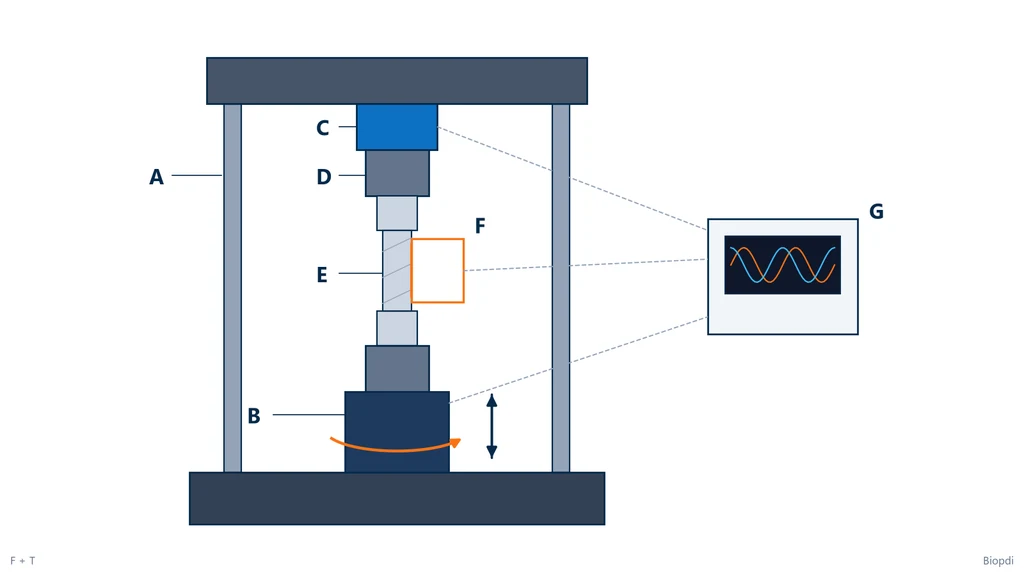
Every axial-torsion machine has the same parts, and their functions complement each other. The diagram below shows a generic fatigue system with the actuator in the base. The frame (A) withstands force and torque without deforming. The actuator (B) applies linear displacement and rotation. The load cell (C) measures both loads. The grips (D) hold the tubular specimen (E) without slipping axially or rotationally. The extensometer (F) measures ε and γ on the gauge section. The controller (G) commands both channels and records the data.
Three parts deserve attention when you buy and use a system. The two-channel load cell has crosstalk: a small part of the force shows up on the torque channel and vice versa. MTS treats this crosstalk as a system specification, and the calibration must cover both channels. The grips must transmit torque without angular backlash, so they use collets, hydraulic jaws or threaded heads instead of ordinary tensile wedge grips. The axial-torsion extensometer measures the relative displacement and rotation between two knife edges on the gauge section. An axial-only extensometer does not measure γ. The load cell and the extensometer each have their own article.
Capacity ranges on the market
Commercial axial-torsion systems range from a few kilonewtons and tens of N·m, for implants and biomaterials, to hundreds of kilonewtons and thousands of N·m, for automotive and aerospace components. The table lists examples published by the manufacturers (pages accessed on October 13, 2026), as a reference range only:
| System | Axial | Torque | Rotation |
|---|---|---|---|
| Instron ElectroPuls E3000 | ±3 kN (±0.67 kip) | ±25 N·m (±220 lbf·in) | up to 16 turns |
| Instron ElectroPuls E10000 | ±10 kN | ±100 N·m | up to 16 turns |
| Instron 8874 | ±25 kN | ±100 N·m | ±130° |
| Instron 8852 and 8854 | ±100 and ±250 kN | ±1,000 and ±2,000 N·m | 90° rotary stroke |
| MTS Series 809 | 25 to 1,000 kN | 220 to 11,000 N·m | ±50° static, ±45° dynamic |
Example 1 shows how to choose. The 25 × 21 mm tube needs 30 kN and 150 N·m just to reach 74% of yield by von Mises, and about 51 kN and 336 N·m to yield on each axis alone. Choose the system capacity for the strongest part you plan to test, with a margin. Choose the rotation for the maximum expected angle. Cable tests, for example, need twists of ±180° to ±270° under tension, according to TPC Wire.
Applications of the axial-torsion test by industry
The axial-torsion test is used where a part works under tension and torsion at the same time, or where the design needs the material's behavior under a multiaxial stress state. The table summarizes the industries and what is tested in each:
| Industry | What is tested | References |
|---|---|---|
| Biomedical | bone screws, spinal and hip implants, Luer connectors, bone tissue | ASTM F543, F1717, F2077; ISO 80369-7 |
| Automotive | half shafts, drive shafts, steering columns, ball joints, fasteners | automaker standards and specifications |
| Aerospace and energy | blades, turbine shafts, high-temperature materials | ASTM E2207 for material data |
| Oil and gas | pipes and connections under drilling weight and torque | product specifications |
| Cables and wires | torsion under tension, wrapping | ASTM A938; ISO 7800 |
| Materials and research | yield surface, multiaxial fatigue, tubular composites | ASTM E2207; literature |
Much of today's demand comes from the medical field. Implant manufacturers need to show how their products behave under the combined loads that occur in the body, and device laboratories test animal tissue and bone under tension and torsion for comparison with the implant. In composites, a filament-wound tube under tension and torsion lets you vary the load ratio and study ply failure. In metals, the test is the main source of data for validating yield criteria and multiaxial fatigue models.
Common mistakes in the axial-torsion test
These mistakes distort the result most, or the way it is read:
- Adding σ and τ. The stresses combine as √(σ² + 3τ²) or √(σ² + 4τ²), never by direct addition.
- Using τ = T·r/J after yielding. Once the material yields, the stress distribution is no longer linear and the formula overestimates the surface stress. This is one of the reasons for using a thin-walled tube.
- Measuring strain from the actuator. In Example 4, the targets were 0.10 mm and 0.86°, which are on the order of the backlash and deformation of the grips. Use an extensometer on the gauge section.
- Misalignment. Eccentricity or tilt between the grips introduces bending, which does not show up on either channel.
- Ignoring the crosstalk of the two-channel load cell, or calibrating only the force channel.
- Treating sequential loading as simultaneous. Tension followed by torque is not the same as both applied in-phase.
- Comparing in-phase and out-of-phase tests at the same equivalent strain as if they were equally severe. Out-of-phase loading usually gives a shorter life.
- Applying ASTM E2207 to components, or outside its scope: with nonzero mean strain or different frequencies on the two channels.
- Citing ASTM F543 as a combined test. Torsion and pull-out are in separate annexes.
- Citing withdrawn standards, such as ISO 594-2 or ISO 1352:2011.
- Ignoring buckling of the tube under compression or high torsion, which can be mistaken for yielding.
- Choosing the machine by the capacity of one axis only. The part must fit within both limits, force and torque, and within the angular stroke.
Axial-torsion testing with Biopdi equipment
Biopdi supplies the axial-torsion universal testing machine, which applies tension and torque to the same part, as well as the torsion testing machine and the universal testing machine. The torsion testing machine comes in two versions: the Basic version, used together with the universal testing machine, and the Complete version, which operates on its own. The universal testing machine handles the axial part: tension, compression and pull-out. For the axial-torsion configuration, force and torque capacities, control mode and test type are defined with the Biopdi technical team, based on the specimen and the loads. The panel below shows the torsion testing machine, the role of each part and the related equipment.
The Biopdi torsion testing machine
Capacities of 1, 5 and 10 N·m (others on request), speed from 0.01 to 200 rpm, angular accuracy of 0.018° and torque accuracy of 0.005 N·m, samples up to 200 mm long. Each part has a function:
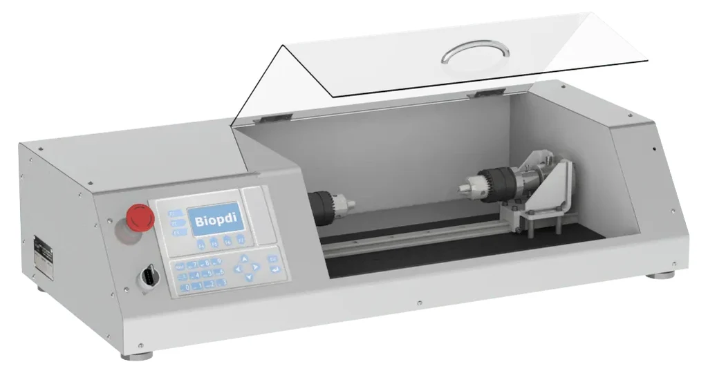
- Motor and rotating chuck rotate one end of the sample at the set speed
- Fixed chuck and transducer measure the torque transmitted through the sample
- Angle measurement records the angle of twist
- Sample supports optional, depending on the part
- Console or software sets up the test and plots torque × angle
- Acrylic guard optional on the Complete version
Versions and related equipment
The Basic version works with the universal testing machine. In the axial-torsion universal testing machine, tension and torque act on the same part, and axial strain is measured with the M2 line:
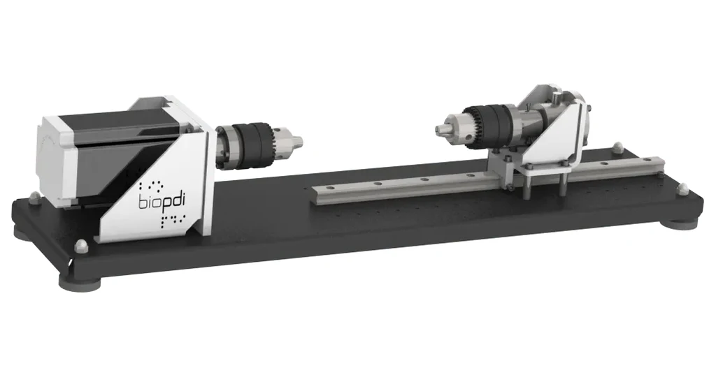
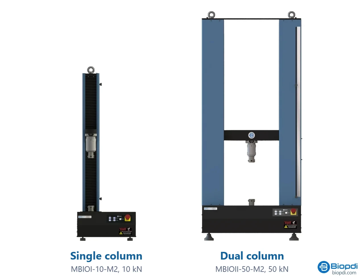
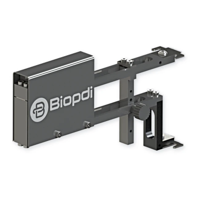
With its range of up to 10 N·m, the torsion testing machine covers thin wires, small screws, dental instruments and small metal and polymer specimens, such as the 4 mm bar in Example 5. The tube in Examples 1 to 3, at hundreds of N·m, falls within the range of the industrial systems in the market table. The M2 line includes single-column models from 200 N to 10 kN and dual-column models from 5 kN to 1,000 kN, and the line's extensometers measure axial strain. For the specifications of the axial-torsion universal testing machine, contact the technical team. For capacities outside these ranges or special setups, see special projects or request a quote. Pure torsion, with the formulas for the modulus G and the torque × angle curve, is covered in the article on the torsion test.
Other tests and technical references
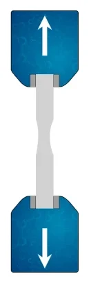
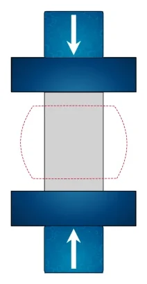
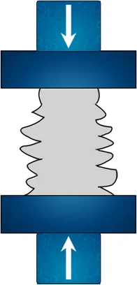
Tests performed on the Biopdi universal testing machine
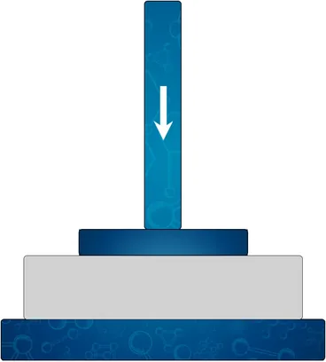
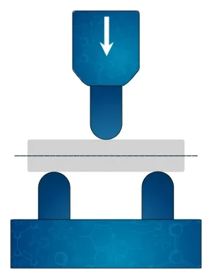

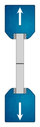


Related technical references
Torsion test: formulas, shear modulus G, fracture and standards
Torsion test: torque is applied to a cylindrical specimen and twist angle measured. Formulas (τ = T·r/J), shear modulus G, fracture, standards.
ASTM E8 vs ISO 6892-1: tensile testing of metals, differences and requirements (NBR ISO 6892-1 and A370)
ASTM E8/E8M-25 and ISO 6892-1:2019, adopted in Brazil as ABNT NBR ISO 6892-1:2024, cover the same tensile test of metals at room temperature. They differ in the specimen gauge length (4D in E8, 5D in E8M and 5.65√S0 in ISO), in speed control and its tolerance, in symbols, in rounding and in the standards for the machine and the extensometer. For that reason, elongation from one cannot be compared directly with elongation from the other.
Weld test specimen: tensile and bend tests per ASME IX, AWS and ISO
Weld test specimen: how to cut, machine and run tensile and bend tests per ASME IX and ISO 15614-1, with the 3 mm and 95% criteria and examples.
Frequently asked questions
What is the axial-torsion test?
It is a test that applies axial force (tension or compression) and torque to the same test specimen, together or separately, in-phase or out-of-phase. The surface is subjected to a normal stress σ = F/A and a shear stress τ = T·r/J, which combine into the von Mises equivalent stress, √(σ² + 3τ²).
What is the difference between a torsion test and an axial-torsion test?
The torsion test applies torque only and measures torque, angle of twist and the shear modulus G. The axial-torsion test applies torque and axial force to the same test specimen and measures the response to the combined stress state, such as the yield surface and the multiaxial fatigue life.
What type of stress does torsion produce?
Shear stress, which is zero at the center and maximum at the surface of a circular bar: τ = T·r/J. At the surface, this shear is equivalent to a tension and a compression of the same magnitude at 45° to the axis, which is why brittle materials fracture along a helix.
How do you calculate the stress in a tube under tension and torsion?
Calculate σ = F/A and τ ≈ T/(2π·rm²·t) and combine them with von Mises: σvM = √(σ² + 3τ²). For a 25 × 21 mm tube with 30 kN and 150 N·m, σ = 207.6 MPa, τ = 90.3 MPa and σvM = 259.9 MPa.
What is the axial-torsion test used for?
To reproduce the stress state of parts that work under tension and torsion at the same time, such as bolts and screws, shafts, implants and cables, and to obtain material data under multiaxial loading: yield surface, failure criterion and in-phase and out-of-phase fatigue life.
What machine performs the axial-torsion test?
A system with a linear and rotary actuator, a force and torque load cell, an axial-torsion extensometer and a two-axis controller, or an axial-torsion universal testing machine. Commercial capacities range from ±3 kN and ±25 N·m to 1,000 kN and 11,000 N·m. Biopdi supplies an axial-torsion universal testing machine, with the specification defined together with our technical team.
What does ASTM E2207 cover?
ASTM E2207-15(2021) is the practice for strain-controlled axial-torsional fatigue testing of thin-walled tubular specimens, in-phase or out-of-phase, at room or elevated temperature. It is limited to zero mean strain, the same frequency on both channels and homogeneous materials, and it does not apply to components.
Is ASTM F543 an axial-torsion test?
No. ASTM F543-23, for metallic bone screws, covers torsion (Annex A1), insertion torque (A2) and axial pull-out (A3) in separate annexes and separate tests; it does not apply tension and torsion at the same time.
What are the types of torsion tests?
Pure torsion to failure or to a set angle, proof torsion (sustained torque), cyclic torsion (fatigue, as in ISO 1352), functional product torsion, and torsion combined with axial load, the axial-torsion test, which can be static or cyclic, in-phase or out-of-phase.
What is an example of combined torsion and tension?
A bolt being tightened: the wrench applies torque, and the preload stretches the bolt shank at the same time. Other examples are a drive shaft under axial load, a steering column, a twisted cable under tension and a bone screw being inserted.