
A shear test measures the force needed to make two parts of a material slide past each other along a plane. Shear strength is τ = F / A in single shear and τ = F / (2A) in double shear, in MPa. In the elastic range, τ = G·γ, and the shear modulus G is related to Young's modulus by G = E / [2(1 + ν)]: about 80 GPa for steel and 25 GPa for aluminum.
Shear is the load that cuts: scissors through paper, the bolt in a joint, the rivet in an aircraft structure, the punch that pierces a sheet. In this guide you will find the concept, the difference between single and double shear, how the test is performed, the shear modulus and how to measure it, the shear strength of metals, shear tests on pins, adhesives, composites, plastics and wood, the formulas, worked examples and the most common mistakes. The soil test, which uses the same word, is covered near the end of the article and in direct shear test.
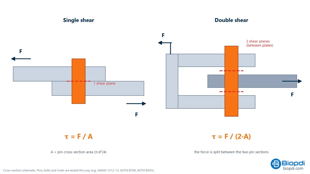
The diagram below shows a pin in the two most common setups: in single shear, the force crosses a single plane of the pin; in double shear, the pin passes through a clevis and the same force is split between two planes, so the stress drops by half.
What is shear
Shear stress (τ) is the component of the internal force that acts parallel to the shear plane, divided by the area of that plane. It differs from normal stress (σ), which acts perpendicular to the plane, as in tension and compression. The corresponding strain is shear strain (γ): how much the right angle between two edges of the material closes, in radians. Think of a deck of cards pushed sideways: the cards slide over one another and the stack tilts.
The shear test uses a fixture mounted on a universal testing machine to force this sliding along a defined plane. The main result is the maximum force and, from it, the shear strength. If the shear strain is also measured, you obtain the material's shear stiffness, the modulus G, which has its own section further on. It is one of the basic mechanical tests, alongside the tensile test and the compression test, and it complements both: tension and compression characterize the material under normal stress, and shear under the stress that makes the parts slide.
In practice, the test is used to:
- Design joints. Pins, bolts, rivets, welds and bonded joints work in shear, and the measured strength is the basis for calculating how many fasteners, and of what diameter, the joint needs.
- Accept lots and control processes. Rivets, wires and fasteners have a specified shear strength; the test confirms whether the lot complies.
- Compare materials and adhesives. The same test, performed the same way, shows which adhesive, alloy or laminate is stronger.
- Investigate failures. In composites, it reveals separation between plies (delamination); in bonded joints, whether failure occurred in the adhesive or at the interface.
Single shear and double shear
The basic calculation of the test is the force divided by the area of the plane that was sheared: τ = F / A, in MPa (N/mm²). In a pin or a round bar, that plane is the cross section, A = π·d² / 4. What changes from one test to another is how many shear planes resist the same force.
In single shear there is one shear plane: a rivet in a lap joint of two sheets, a bonded joint, the shearing of a sheet. In double shear there are two: a pin passing through a clevis and a central bar. The same force is split between the two planes, so the stress is half: τ = F / (2A). Confusing the two cases is the most common mistake in this test, and it doubles or halves the result. Double shear is preferred for fasteners because the symmetry reduces pin bending; it is the method of ASTM B769 (aluminum alloys), ASTM B565 (rivets) and NASM 1312-13 (aerospace fasteners).
For design, the same calculation is done in reverse: the force a pin can carry is F = τ·n·π·d² / 4, where n is the number of shear planes.
How the shear test is performed
The universal testing machine applies a tensile or compressive force. What turns that motion into shear is the fixture: two rigid parts, mounted against each other, that force the specimen to slide along a defined plane without bending. That is why the fixture is made with small clearances and controlled cutting edges; if the specimen bends, the measured force is no longer pure shear. The three most common arrangements are:
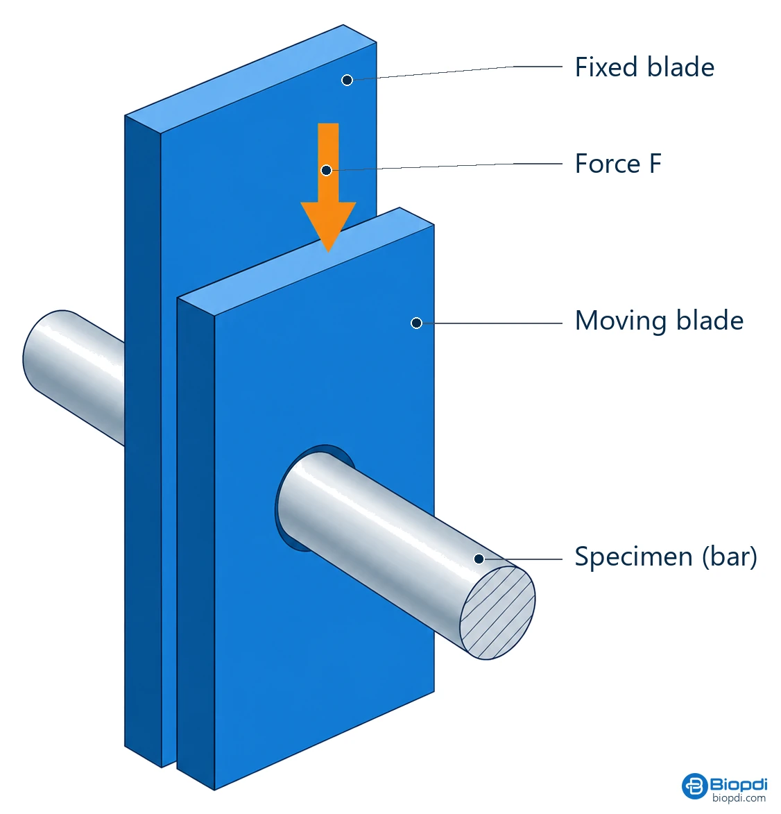
- Fixed blade and moving blade: the cylindrical specimen passes through the blades and the moving blade slides flush against the fixed one, shearing it in one or two planes.
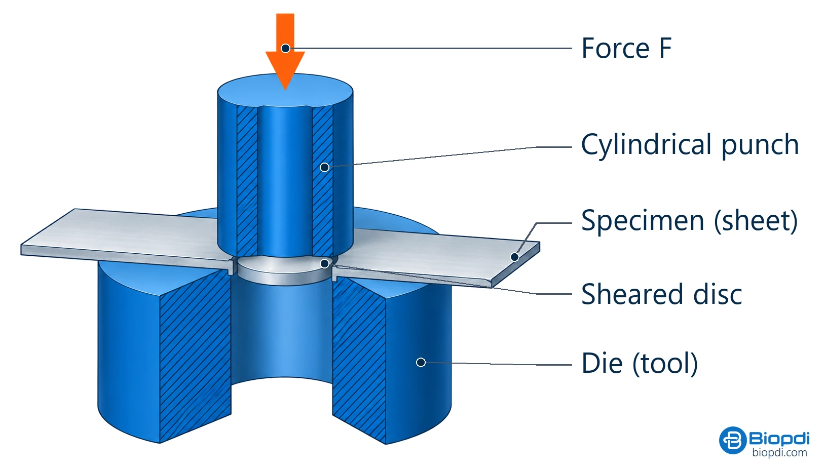
- Punch: a cylindrical punch goes through a plate or sheet supported on a die and blanks out a disk. The sheared area is the side of that disk, the punch perimeter times the thickness.
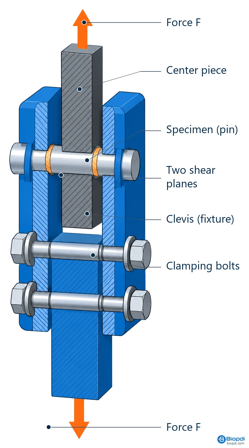
- Clevis for shaft or pin: the pin passes through the clevis and the central part and is sheared in the two planes between them, in double shear.
The images below show these three fixtures, in the same order as the list: the blades shearing the cylindrical specimen, the punch blanking the disk and the clevis with the shaft shear zone.
Shear fixture with fixed blade and moving blade
Punch shear: the punch blanks the disk out of the specimen
Double shear fixture for a shaft or pin
What is recorded during the test
The crosshead moves the fixture at constant speed, and the system records force and displacement at every instant:
- Force: measured by the load cell, which converts force into an electrical signal read by the software.
- Displacement: read from the crosshead or, when the strain of the material must be measured, by a sensor attached to the specimen itself.
- Force vs. displacement curve: rises to the maximum force, which gives the shear strength; fracture appears as a sudden drop in force.
For strength, the maximum force and the area are enough. For stiffness, you need the shear strain measured on the specimen, as shown in the section on the modulus G.
Test specimen and test conditions
There is no single shear test specimen: the shape depends on the material and the standard. Metals are tested as cylindrical bars, pins, rivets and wires, or as sheet strips; adhesives, as joints of two lap-bonded adherends; composites, as short beams or as V-notched bars; plastics, as plates for the punch. Each format is detailed in the section by material.
Some requirements apply to all of them. The area goes directly into the calculation, so dimensions are measured on the actual specimen before the test. The faces in the shear zone must be regular, with no burrs or unintended notches, which would concentrate stress and make the specimen fail early. Temperature, humidity and loading rate follow the standard and go into the report, because they change the result, especially for adhesives and polymers.
Shear modulus (G)
The shear modulus, also called the modulus of rigidity, is the ratio τ / γ in the elastic range. It measures the material's stiffness against distortion, just as the modulus of elasticity E measures stiffness in tension. In isotropic materials the two are linked by Poisson's ratio:
G = E / [2(1 + ν)]
Since ν lies between 0 and 0.5, G lies between E/3 and E/2. For most metals, with ν close to 0.3, G ≈ 0.4·E.
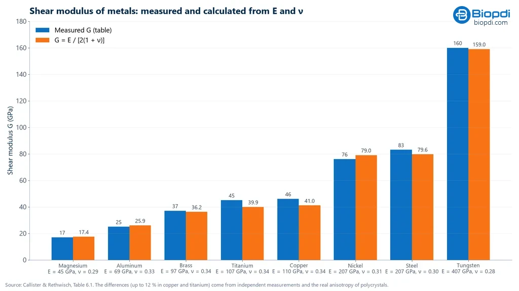
The chart below compares, for eight metals, the measured G with the G calculated from E and ν using the formula. For common metals the two bars are close, which confirms the formula as a good estimate when no test is available.
The table gives the measured values of E, G and ν used in the chart:
| Metal | E (GPa) | G (GPa) | ν |
|---|---|---|---|
| Magnesium | 45 | 17 | 0.29 |
| Aluminum | 69 | 25 | 0.33 |
| Brass | 97 | 37 | 0.34 |
| Titanium | 107 | 45 | 0.34 |
| Copper | 110 | 46 | 0.34 |
| Nickel | 207 | 76 | 0.31 |
| Steel | 207 | 83 | 0.30 |
| Tungsten | 407 | 160 | 0.28 |
Source: Callister and Rethwisch, Materials Science and Engineering: An Introduction, Table 6.1. Calculated with the formula, G matches the measured value within about 5% for almost all metals; for copper and titanium the difference reaches 12%, because E, G and ν come from independent measurements and real metals are not perfectly isotropic. Other sources give slightly different values (steel from 76 to 83 GPa, depending on the alloy). For design, use the measured value. In composites and wood, which are anisotropic, the formula does not apply: G depends on the plane.
How to measure the shear modulus
- By torsion (ASTM E143): torsion produces pure shear at the surface of a shaft, and G = T·L / (J·θ). See torsion test.
- In composites, with the V-notch tests (ASTM D5379 and D7078) using strain gauges at ±45°, or by tension of a ±45° laminate (ASTM D3518).
- By impulse excitation, a dynamic non-destructive technique.
Crosshead displacement cannot be used to calculate G: it includes clearances and the deformation of the fixture. γ must be measured on the specimen itself.
Shear strength of metals
Shear strength is the highest shear stress the material withstands before fracture, τu = Fmax / A. There is no single value "for steel": it depends on the alloy and the heat treatment. When no test is available, estimates are used:
| Quantity | Estimate | Validity |
|---|---|---|
| Ultimate shear strength | τu ≈ 0.6 × Rm | rule of thumb; across 197 aluminum alloys, mean error of 5.5% (Tatara, 2022) |
| Shear yield strength (von Mises) | τy = σy / √3 ≈ 0.577·σy | isotropic ductile metals |
| Shear yield strength (Tresca) | τy = 0.5·σy | more conservative criterion |
Example: a steel with a yield strength of 250 MPa and an ultimate tensile strength of 400 MPa has a shear yield strength of about 144 MPa (von Mises) or 125 MPa (Tresca) and an estimated shear strength of 240 MPa. These are estimates: the 0.6 rule is not a standard and may fail for austenitic stainless steels. The starting ultimate tensile strength comes from the tensile test.
Types of shear test by material
The principle is always the same, but each material needs its own fixture and test specimen, because each one fails in a different way:
- Metals. Bars, forgings, rivets, wire, bolts and pins are tested in double shear, with a clevis-type or blade-type fixture. Thin sheet is tested in single shear, with a dedicated test specimen. In welded steel wire mesh for concrete reinforcement, the test is done on the welded intersection, which transfers the force from one wire to the other.
- Adhesives. The test measures the bonded joint, not the adhesive alone: the adhesive layer between two strips is loaded in shear. This is the lap shear test, described in detail below.
- Composites. Strength depends on direction. Between plies, the weak point is the matrix that holds them together, and the test looks for delamination. In the plane of the laminate, the strength and the modulus G depend on fiber orientation. Each case has its own test, and sandwich panels also have a test for the core.
- Plastics. Plates are tested by punch shear, with the fixture described in "How the shear test is performed".
- Wood. As with composites, strength depends on the grain direction: the test shears parallel to the grain and, in glued laminated timber (glulam), also along the glue line.
The table summarizes the test and the standard for each case:
| Material | Test | Standard |
|---|---|---|
| Aluminum alloys (bars, forgings, castings) | cylindrical double shear | ASTM B769-25 |
| Aluminum rivets and wire | double shear | ASTM B565-20 |
| Thin aluminum sheet | single shear on sheet | ASTM B831-25 |
| Bolts and pins | double shear | NASM 1312-13 |
| Metal-to-metal adhesive | single lap joint (lap shear) | ASTM D1002, ISO 4587 |
| Adhesive on plastics and composites | lap shear | ASTM D3163, ASTM D5868 |
| Composite, interlaminar | short beam in 3-point bending (short beam shear) | ASTM D2344-22 |
| Composite, in-plane | V-notch (Iosipescu and V-notched rail) | ASTM D5379-19(2026), D7078-20(2025) |
| Composite, in-plane | tensile test of ±45° laminate | ASTM D3518-18(2025) |
| Sandwich panel core | core shear | ASTM C273-20 |
| Plastics | punch shear | ASTM D732 |
| Wood and glued laminated timber | shear parallel to the grain and along the glue line | ASTM D143-25, ABNT NBR 7190-3 and 7190-6 (Brazilian timber structures standards) |
| Welded steel wire mesh | shear of the welded intersection | ABNT NBR 5916:2026 (Brazilian standard) |
Adhesives: the lap shear test
Two strips bonded with an overlap are pulled in tension until failure, and the strength is the maximum force divided by the bonded area, τ = F / (b·L), where b is the width and L the overlap length. In ASTM D1002, the strips are 25.4 mm wide and the overlap is 12.7 mm (an area of 322.6 mm²). The result is called the apparent shear strength: the eccentricity of the joint also creates a peel component, and stress concentrates at the edges of the overlap. That is why lap shear is used to compare adhesives and control processes, and ISO 4587 itself warns that it does not provide design data. The failure mode also goes into the report: cohesive (within the adhesive) or adhesive (at the interface).
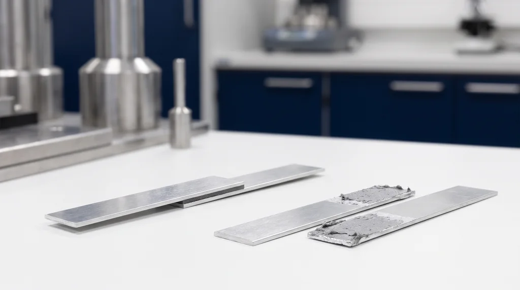
The photo shows two aluminum test specimens: one intact, before the test, and one fractured. On the fractured one there is adhesive on both faces of the overlap, a sign that the fracture went through the adhesive, which is a cohesive failure.
Composites: short beam and V-notch
The short beam test (ASTM D2344) is a three-point bend test with a span of only 4 times the thickness, so that the beam fails by shear between the plies and not by bending: Fsbs = 0.75·Pmax / (b·h). If the fibers on the face break, the result is not valid as an interlaminar strength. For in-plane shear and the modulus G, V-notched test specimens (D5379 and D7078) are used, instrumented with strain gauges at ±45°. The rail shear standard ASTM D4255 was withdrawn in 2025.
How to calculate: shear test formulas
Every calculation in the test divides a force by the area that resists it; what changes is which area applies in each case. The table brings together the formulas covered throughout the article, and the exercises that follow apply each one of them.
| Quantity | Formula | Unit and note |
|---|---|---|
| Shear stress (single shear) | τ = F / A | MPa; A is the area of the shear plane |
| Double shear (pin in a clevis, rivet) | τ = F / (2A) | two planes resist the same force |
| Area of a pin | A = π·d² / 4 | mm² |
| Shear strain | γ ≈ δ / h | rad; δ is the lateral displacement and h the height |
| Hooke's law in shear | τ = G·γ | G in GPa |
| Relationship between elastic constants | G = E / [2(1 + ν)] | isotropic materials only |
| Torsion of a solid shaft | τ = T·r / J, with J = π·d⁴ / 32 | T is the torque and r the radius |
| Modulus from torsion | G = T·L / (J·θ) | θ is the angle of twist, in rad |
| Bonded joint (lap shear) | τ = F / (b·L) | b is the width and L the overlap |
| Punch shear (plastics, sheet) | τ = F / (π·D·t) | D is the punch diameter and t the thickness |
Solved shear exercises
1. Pin in double shear. A 10 mm steel pin connects a clevis to a bar and failed at 20 kN. The area is π × 10² / 4 = 78.54 mm². With two planes: τ = 20,000 / (2 × 78.54) = 127.3 MPa. Calculated as single shear, it would give 254.6 MPa, twice the value.
2. Lap shear (ASTM D1002). Aluminum joint bonded with epoxy, 25.4 × 12.7 mm, maximum force of 6.5 kN with failure in the adhesive: τ = 6,500 / 322.6 = 20.1 MPa.
3. G from E and ν. Steel (E = 207 GPa, ν = 0.30): 207 / 2.60 = 79.6 GPa. Aluminum (69 GPa; 0.33): 25.9 GPa. Copper (110 GPa; 0.34): 41.0 GPa, versus 46 GPa measured.
4. G from torsion. Solid steel bar, 10 mm in diameter with a 100 mm gauge length. Under a torque of 20 N·m, it twisted 1.46° in the elastic range. J = π × 10⁴ / 32 = 981.7 mm⁴; τmax = 20,000 × 5 / 981.7 = 101.9 MPa; θ = 0.02548 rad; γ = 5 × 0.02548 / 100 = 0.001274; G = 101.9 / 0.001274 ≈ 80 GPa.
5. Composite short beam (ASTM D2344). Carbon/epoxy laminate 6.0 mm wide and 3.0 mm thick, 12 mm span, maximum force of 1.20 kN with interlaminar failure: Fsbs = 0.75 × 1,200 / (6.0 × 3.0) = 50.0 MPa.
6. Punch shear of plastic (ASTM D732). 3.0 mm plate, 25.4 mm punch, force of 12 kN. Sheared area: π × 25.4 × 3.0 = 239.4 mm²; τ = 12,000 / 239.4 = 50.1 MPa. The same logic gives the force required by an industrial punch press: shear strength × perimeter × thickness.
Common mistakes in shear testing
- Confusing single shear with double shear. The result doubles or drops by half.
- Calculating G from crosshead displacement. Backlash and fixture deformation contaminate the value; measure γ on the test specimen.
- Bending in the pin. Clearance between pin and hole, or shear planes too far apart, create a bending moment, and the failure is no longer pure shear. That is why fixtures have tight tolerances: ASTM B769 limits the radius of the cutting edges to 0.013 mm.
- Misalignment in the V-notch test: the load line must pass through the notch root.
- Treating lap shear as pure shear. The result is apparent and comparative.
- Treating punch shear as a pure material property. The value depends on thickness.
- Accepting a short beam test with bending failure. The result is invalid.
- Treating "0.6 × Rm" as a standard. It is a rule of thumb.
- Using G = E / [2(1 + ν)] for composites or wood. The formula is valid only for isotropic materials.
Soil shear: the direct shear test
In geotechnics, "shear test" almost always means the direct shear test (ASTM D3080): a soil sample confined in a split box is sheared under a normal stress. Here strength is not a single material value, as it is for a metal: it increases with normal stress, according to the Mohr-Coulomb criterion, τ = c + σ·tan φ, where c is cohesion and φ the friction angle. It is a different family of tests, explained in direct shear test, performed on the Biopdi direct shear apparatus. The CBR test, which shows up in the same searches, measures the bearing capacity of pavement soils: see CBR test.
How to perform the shear test on a universal testing machine
Because shear depends only on the fixture, the same universal testing machine that performs tensile and compression tests also performs this test: just change the fixture and enter the area in the software, which calculates τ = F / A or F / 2A. The Biopdi universal testing machine line performs tensile, compression, flexural, shear, bend, cupping, pull-out and bond tests, with shear fixtures for fasteners and pins, sandwich cores (ASTM C273), wood (NBR 7190-6) and welded wire mesh (NBR 5916). The panel below shows the machine, the role of each part in the shear test and the fixtures used.
The universal testing machine in the shear test
The M2 line includes single-column models, from 200 N to 10 kN, and dual-column models, from 5 kN to 1,000 kN. Each part of the machine has a role in the test:
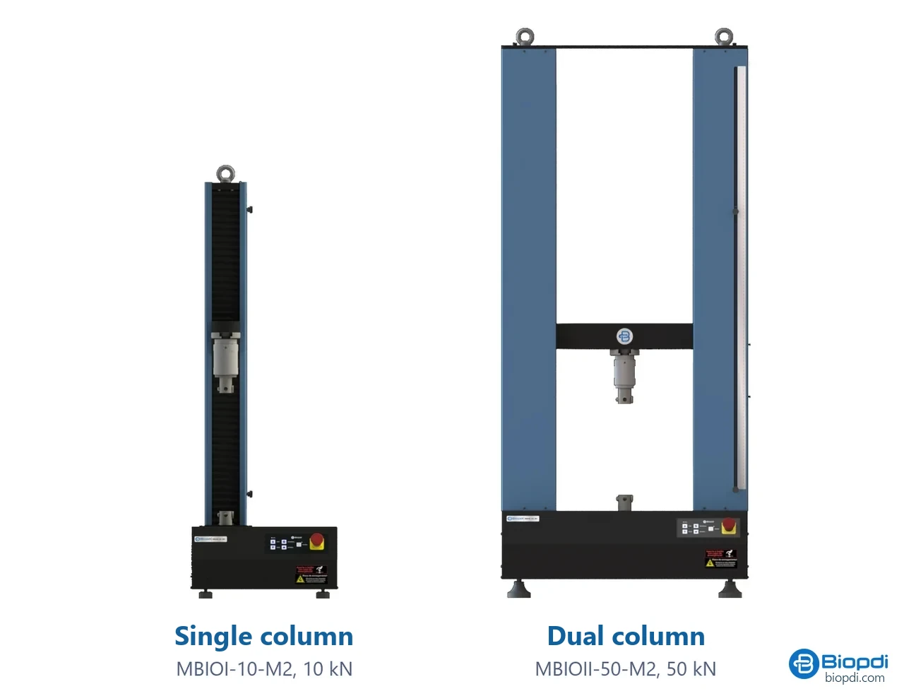
- Moving crosshead pulls or compresses the fixture
- Load cell measures the shear force, class 1
- Fixture single shear, double shear, sandwich or bonded joint
- Displacement crosshead or extensometer
- BioLab software calculates τ = F/A and the report
- Control panel and emergency stop positions and stops the test
Fixtures for the shear test
The fixtures below are mounted on the same machine, depending on the test specimen and the standard:
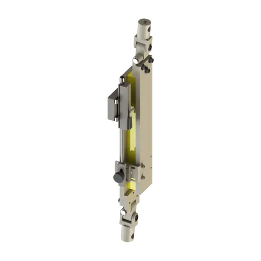
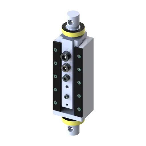
| Application | Force range | Biopdi model |
|---|---|---|
| Adhesive lap shear, plastics | 2 to 10 kN | MBIOI-10-M2 |
| Pins, fasteners, sheet, composites | 5 to 50 kN | MBIOII-50-M2 |
| Large-diameter fasteners | 100 to 200 kN | MBIOII-200-M2 |
To measure G by torsion, see also the torsion testing machine.
Other tests and technical references
Tests performed on the Biopdi universal testing machine

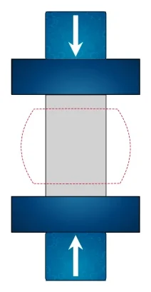
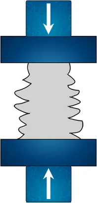
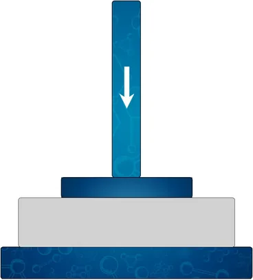




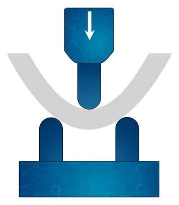
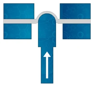
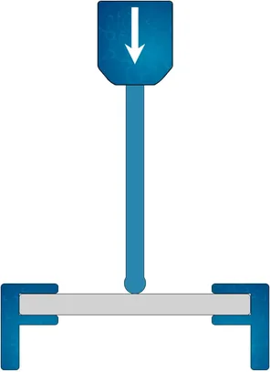
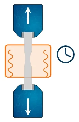


Related technical references
Torsion test: formulas, shear modulus G, fracture and standards
Torsion test: torque is applied to a cylindrical specimen and twist angle measured. Formulas (τ = T·r/J), shear modulus G, fracture, standards.
Materials testing: what it is, types, destructive and non-destructive testing, standards and how to choose
Materials testing is the standardized procedure that measures the mechanical, physical, chemical or microstructural properties of a representative sample, or that inspects a part without damaging it. See the five families of tests, the difference between destructive and non-destructive testing, the test specimen, accreditation, the standards and how to choose the right test.
Mechanical testing: what it is, types, what each test measures and standards
Mechanical tests apply a controlled load to a test specimen and measure the material's response. See the types (destructive, non-destructive, static and dynamic), what each test measures, the standards and the machine for each one.
Frequently asked questions
What is shear? Give examples.
Shear is the loading that makes two parts of a material slide over each other along a plane, which creates a stress parallel to that plane. Examples include scissors cutting paper, the bolt or pin in a joint, a rivet in a structure, and a punch piercing a sheet.
How do you calculate shear stress?
Divide the force by the area of the sheared plane: τ = F / A, in MPa. In double shear, with two planes, τ = F / (2A). A 10 mm pin in double shear that fails at 20 kN has a shear strength of 127.3 MPa.
What is the formula for shear force?
F = τ·A. To size a pin, the allowable force is allowable τ × n × π·d² / 4, where n is the number of shear planes.
What is the shear modulus?
It is the ratio of shear stress to shear strain in the elastic range, G = τ / γ. It is also called the modulus of rigidity or transverse modulus of elasticity. Steel has a shear modulus of about 80 GPa and aluminum about 25 GPa.
What is the formula for the shear modulus?
G = τ / γ. For an isotropic material, G = E / [2(1 + ν)], where E is Young's modulus and ν is Poisson's ratio. For steel, 207 / (2 × 1.30) ≈ 80 GPa.
What is the shear modulus of aluminum?
About 25 to 26 GPa, with E of 69 GPa and ν of 0.33.
What is the shear strength of steel?
It depends on the steel. As an estimate, the ultimate shear strength is about 0.6 times the ultimate tensile strength, and the shear yield strength is 0.577 times the tensile yield strength (von Mises). For design, use test results or the material specification.
What is the difference between single shear and double shear?
Single shear has one shear plane and double shear has two. For the same force, the stress in double shear is half: τ = F / (2A).
What is the lap shear test?
It is a test on a single-lap bonded joint, pulled in tension until it fails. The strength is the maximum force divided by the bonded area, per ASTM D1002 or ISO 4587. The result is an apparent strength and is used to compare adhesives.
How do you measure the shear modulus?
By torsion, per ASTM E143, measuring torque and angle of twist. For composites, use the V-notched specimen tests (ASTM D5379 and D7078) with strain gauges at ±45°. Crosshead displacement is not suitable.
What is the direct shear test?
It is a soil test. The sample is confined in a split shear box and sheared under a normal stress to obtain cohesion and the friction angle, per ASTM D3080. The strength follows the Mohr-Coulomb criterion, τ = c + σ·tan φ.
How is the shear test related to the torsion test?
Torsion produces pure shear at the surface of a shaft. That is why it is the classic method for measuring the shear modulus and the shear strength of metals.