
A hardness test is the standardized measurement of a material's resistance to localized indentation: an indenter of defined geometry is pressed into the part with a controlled force for a controlled time, and hardness is calculated from the size of the indentation (Brinell, Vickers, Knoop) or from its depth (Rockwell). A result is only valid with the full scale designation, such as 60 HRC, 350 HBW 5/750 or 640 HV 30, because each method gives a different number for the same material.
The most widely used methods are Brinell (ISO 6506-1), Rockwell (ISO 6508-1:2023), Vickers and microhardness (ISO 6507-1:2023), Knoop (ISO 4545-1:2023), Shore for rubbers and plastics (ASTM D2240, ISO 48-4 and ISO 868) and portable Leeb (ISO 16859-1). Below is the procedure for each one, with the parameters of the current standard, specimen preparation, hardness tester verification and the test report. The concept, the complete formulas and the HRC, HV and HB conversion table are covered in the article hardness of materials.
How the hardness test works
Every indentation hardness test has the same three elements. The indenter has a geometry fixed by the standard: a hardmetal (tungsten carbide) ball, a diamond cone or a diamond pyramid. The force is known and applied without shock, perpendicular to the surface. The time of application and of dwell is also fixed, because the material keeps flowing while the force acts.
What is measured splits the methods into two groups. In the optical methods (Brinell, Vickers and Knoop), the force is removed and the indentation is measured under a microscope; hardness is force divided by area, and a small indentation means a hard material. In Rockwell, the instrument measures the depth of the indentation and shows the hardness directly on the display.
All of these methods are static: the force rises in a controlled way and is held for a few seconds. The dynamic method in common use is Leeb, in which an impact body strikes the part and the instrument compares the rebound velocity with the impact velocity; for this reason the reading also depends on the elastic properties of the material.
The diagram below shows, not to scale, the quantity read in each of the three most common bench methods: the diameter d of the spherical cap in Brinell, the permanent depth h in Rockwell, measured from a reference plane created by the preliminary force, and the two diagonals of the rhombus in Vickers.
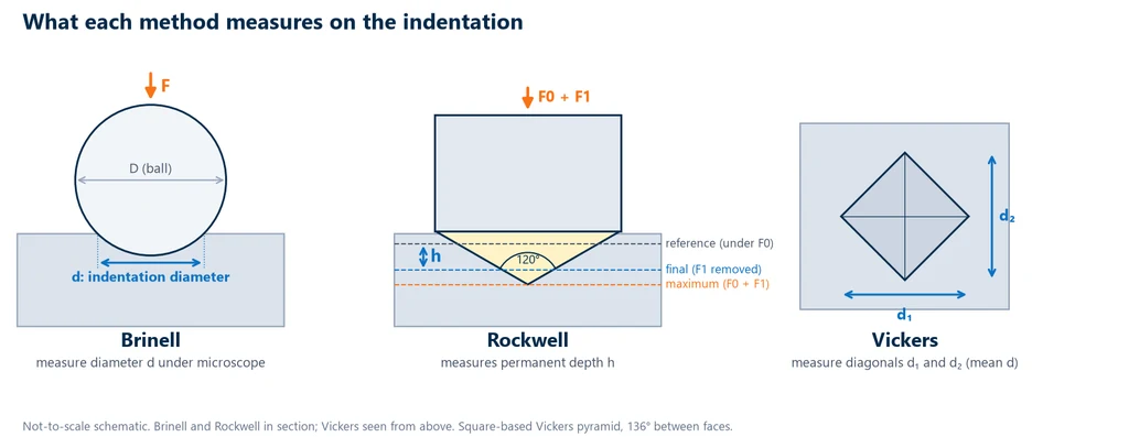
Hardness is a comparative measurement that depends on the indenter, the force and the time. The test leaves a mark, small in Rockwell and Vickers and larger in Brinell, and on a finished part the measuring point must be able to accept that mark.
Types of hardness test
Each type of hardness test combines an indenter with a measured quantity and covers a range of materials. The table summarizes the six methods; each one has a section further below with the step-by-step procedure of its standard.
| Method | Indenter | What is measured | Typical use |
|---|---|---|---|
| Brinell (HBW) | Hardmetal ball from 1 to 10 mm | Indentation diameter | Cast iron, forgings, annealed steels, nonferrous alloys |
| Rockwell (HRC, HRBW, N, T) | 120° diamond cone or hardmetal ball of 1.5875 or 3.175 mm | Permanent depth under preliminary force | Hardened steel, production control, sheet (superficial scales) |
| Vickers (HV) | Square-based diamond pyramid | Mean of the two diagonals | Any metal, from soft to hardmetal; welds; thin parts |
| Knoop (HK) | Rhombic-based diamond pyramid | Long diagonal | Very thin layers, coatings, brittle materials |
| Shore (A, D and others) | Indenter with calibrated spring | Penetration, read from 0 to 100 | Rubbers, elastomers and plastics |
| Leeb (HL) | Impact body with ball | Ratio of rebound velocity to impact velocity | Large or assembled parts, in the field |
Among the mechanical tests, hardness is one of the few performed on the part itself, without a machined test specimen. There is also a portable method without rebound, UCI (ultrasonic contact impedance), covered together with Leeb.
Brinell hardness test step by step
In Brinell, a hardmetal ball of diameter D is pressed with force F; once the force is removed, the diameter d of the spherical cap is measured. Hardness is the force divided by the curved area of the indentation, HBW = 0.102 × 2F / [πD(D − √(D² − d²))], with F in newtons and D and d in millimeters (the derivation is in hardness of materials). The W in the symbol indicates a hardmetal ball, the only one permitted in ISO 6506-1:2014, an edition confirmed in 2019 and under revision at ISO.
The main decision is the choice of D and F. The standard uses the force-diameter ratio 0.102·F/D², which depends on the material and the expected hardness, and calls for the largest ball the part will accept, because a large indentation averages over many grains. The ratios recommended by ISO 6506-1 are these:
| Material | Brinell hardness | Ratio 0.102·F/D² |
|---|---|---|
| Steel, nickel alloys and titanium alloys | any | 30 |
| Cast iron (2.5, 5 or 10 mm ball) | below 140 / 140 or more | 10 / 30 |
| Copper and copper alloys | below 35 / 35 to 200 / above 200 | 5 / 10 / 30 |
| Light metals and their alloys | below 35 / 35 to 80 / above 80 | 2.5 / 5, 10 or 15 / 10 or 15 |
| Lead and tin | any | 1 |
With ratio 30 and the 10 mm ball, the force is 29.42 kN (6,614 lbf); with the 5 mm ball, 7.355 kN (1,653 lbf). The procedure follows these steps:
- Prepare the surface: smooth and flat, free of scale and lubricant; with small balls, polishing may be needed.
- Check the thickness: at least 8 times the indentation depth (Annex B of the standard).
- Apply the force: perpendicular, without shock, reaching full force in 2 to 8 s (7 s nominal).
- Hold the force: 10 to 15 s (14 s nominal); a longer time goes in the designation.
- Position the indentations: center at least 2.5 d from the edge and 3 d from the center of the adjacent indentation.
- Measure two perpendicular diameters and use the mean. d must be between 0.24D and 0.6D; outside this range, the test report records d/D.
The test is performed between 10 °C and 35 °C. The designation gives the value, the symbol, the ball diameter, the force in kgf and, if different from the standard one, the time: 350 HBW 5/750 is a hardness of 350 with a 5 mm ball and 750 kgf; 600 HBW 1/30/20 used a 1 mm ball, 30 kgf and a 20 s dwell.
Rockwell hardness test step by step
Rockwell applies two forces. The preliminary force F0 seats the indenter and defines the reference plane, below the surface irregularities. The additional force F1 drives the indenter to maximum depth. When F1 is removed, part of the deformation recovers (elastic recovery), and the instrument reads, still under F0, the permanent depth h. Hardness is HR = N − h/S, where N is 100 or 130 depending on the scale and S is 0.002 mm on the regular scales and 0.001 mm on the superficial scales (ISO 6508-1:2023). On the C scale, HRC = 100 − h/0.002: each HRC point corresponds to 0.002 mm of depth.
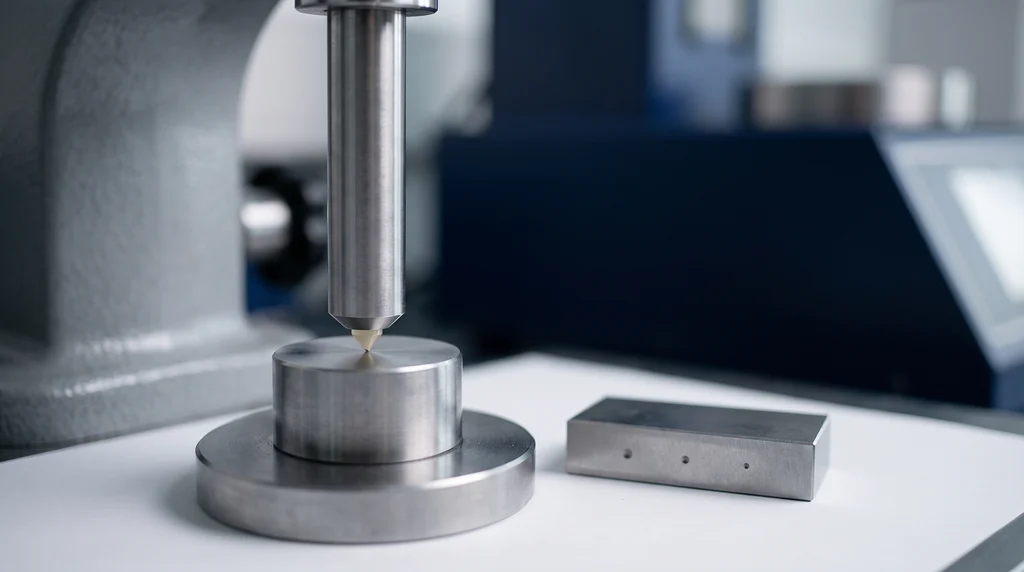
In the photo, the diamond indenter of a Rockwell hardness tester rests on the ground face of a steel part; beside it, a reference block with small indentations, used to verify the instrument. The reference block is a block of certified hardness.
The step-by-step procedure per ISO 6508-1:2023 is as follows:
- Verify the instrument on the reference block before the first test of the day, on each scale. After changing the indenter or the anvil, make two tests, discard them and verify again.
- Support the part on a rigid anvil, perpendicular to the indenter; a cylindrical part goes on a V-block of at least 60 HRC.
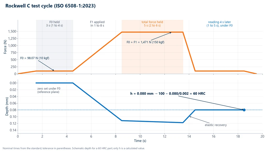
- Apply F0 within 2 s: 98.07 N (22.05 lbf) on the regular scales or 29.42 N (6.614 lbf) on the superficial scales. Hold for 3 s, with a tolerance of 1 to 4 s.
- Apply F1 in 1 to 8 s on the regular scales, or within 4 s on the superficial scales.
- Hold the total force for 5 s (2 to 6 s). Material that keeps sinking under load requires a longer time, recorded in the designation (for example, 65 HRF/10 s).
- Remove F1 and read 4 s later (1 to 5 s), still under F0.
The chart below shows this cycle on a 60 HRC part: at the top, force versus time with the times from the standard; at the bottom, the depth, zeroed under F0, which rises with F1, recovers on removal and stops at h = 0.080 mm.
Because the zero is set under the preliminary force, Rockwell is not very sensitive to fine roughness. Each scale letter combines an indenter and a force; the table shows the most used ones (ISO 6508-1:2023, Tables 1 and 2):
| Scale | Indenter | Preliminary and total force | Application range |
|---|---|---|---|
| HRA | Diamond cone | 98.07 N and 588.4 N (132.3 lbf) | 20 to 95 HRA |
| HRBW | 1.5875 mm ball | 98.07 N and 980.7 N (220.5 lbf) | 10 to 100 HRBW |
| HRC | Diamond cone | 98.07 N and 1.471 kN (330.7 lbf) | 20 to 70 HRC |
| HRFW | 1.5875 mm ball | 98.07 N and 588.4 N (132.3 lbf) | 60 to 100 HRFW |
| HR15N, HR30N, HR45N | Diamond cone | 29.42 N and 147.1, 294.2 or 441.3 N | superficial, for case layers and sheet |
| HR15TW, HR30TW, HR45TW | 1.5875 mm ball | 29.42 N and 147.1, 294.2 or 441.3 N | superficial, for thin sheet of soft material |
The C scale is the one used to control quenching and tempering; the B scale, with a ball, is for soft steels and copper alloys; the N and T scales, with lower forces, are for thin parts and shallow case layers.
Two precautions complete the method. The minimum thickness is 10 h with the cone and 15 h with the ball (charts in Annex B). On a convex surface, the reading comes out lower and receives the correction from Annex C (cylinders) or Annex D (spheres); corrections above 3 points on the A, C and D scales, or 5 points on the B, F and G scales, are not accepted, and a concave surface is only tested by agreement. The designation is the value followed by the scale, such as 60 HRC, 45 HRBW or 70 HR30TW.
Vickers hardness test: macro and low force
Vickers uses a square-based diamond pyramid with 136° between opposite faces. The indentation is a rhombus; the two diagonals are measured under a microscope and their mean d is used. Hardness is HV = 0.1891 F/d², with F in newtons and d in millimeters (details in hardness of materials). Because the indentation has the same shape at any force, a single scale covers everything from soft metal to hardmetal.
ISO 6507-1:2023 divides the method into three force ranges, and the name of the test changes with them:
| Range | Force | Symbols |
|---|---|---|
| Vickers | 49.03 N or more | HV 5 or more |
| Low-force Vickers | from 1.961 N to less than 49.03 N | from HV 0.2 to less than HV 5 |
| Vickers microhardness | from 0.009807 N to less than 1.961 N | from HV 0.001 to less than HV 0.2 |
The number after HV is the force in kilogram-force: HV 30 was measured with 294.2 N. In all ranges, the valid diagonal is from 0.020 mm to 1.400 mm. The procedure is as follows:
- Check the thickness: at least 1.5 times the diagonal, with no visible mark on the back. The indentation depth is about d/7.
- Apply the force in 2 to 8 s (7 s nominal) and hold it for 10 to 15 s (14 s nominal).
- Position: in steel, copper and copper alloys, the center is at least 2.5 d from the edge and 3 d from the adjacent center; in light metals, lead, tin and their alloys, 3 d from the edge and 6 d between centers. With indentations of different sizes, the diagonal of the larger one applies.
- Measure both diagonals. If they differ by more than 5%, the difference goes in the test report.
The designation gives the value, the symbol and the force: 640 HV 30. Vickers is preferred when the part is too thin for Brinell or when very different materials need to be compared on the same scale.
Vickers and Knoop microhardness
In microhardness testing, the force is below 1.961 N (HV 0.2) and the indentation diagonal is in the range of tens of micrometers. The test then measures microstructural constituents, layers and coatings, on a polished section read with high-magnification objectives. Below the minimum diagonal of 0.020 mm, the way forward is instrumented indentation per ISO 14577-1:2026, which records force and depth throughout the cycle.
Knoop (ISO 4545-1:2023) uses a rhombic-based diamond pyramid, with angles of 172.5° and 130° between opposite edges. The indentation is narrow and elongated, and only the long diagonal is measured. For the same force it is shallower than a Vickers indentation: the standard accepts a coating from 0.007 mm at the surface, versus 0.030 mm for Vickers. If the two halves of the long diagonal differ by more than 5%, the indentation is misaligned and is discarded.
Hardness profile and case depth
The most frequent use of low-force Vickers and microhardness is measuring the depth of a hardened layer. On a polished cross section, a row of indentations is made at increasing distances from the surface and hardness is plotted against distance. ISO 18203:2026, which absorbed the former ISO 2639, defines the case depths; the two most used are these:
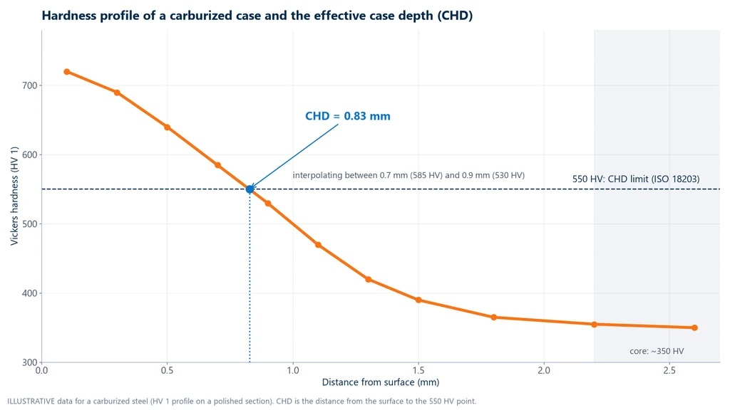
- CHD, carburized case: distance from the surface to the point where hardness drops to 550 HV, the criterion used to control carburizing.
- NHD, nitrided case: distance to the point where hardness is 50 HV above the core hardness, used in nitriding.
The chart below shows an illustrative profile of carburized steel, from 720 HV near the surface to about 350 HV in the core. The 550 HV point lies between the readings at 0.7 mm (585 HV) and 0.9 mm (530 HV), and linear interpolation gives CHD = 0.7 + (585 − 550)/(585 − 530) × 0.2 = 0.7 + 0.127 = 0.83 mm.
The minimum distance between centers is usually larger than the desired depth step, so the indentations are placed in a zigzag, offset laterally. The limit and the force are stated in the specification, and the standard allows a different limit by agreement.
Shore hardness test
The Shore test measures how far a spring-loaded indenter penetrates rubbers, elastomers and plastics. The instrument is the durometer, and the reading ranges from 0 (full penetration) to 100 (no penetration). Scale A is for soft materials such as rubbers. Scale D has a sharper tip and a stronger spring and is used for rigid plastics and hard rubbers. Under ISO 48-4, readings above 90 Shore A move to the D scale, and readings below 20 Shore D move back to the A scale.
The reading time is critical. The polymer keeps yielding under the spring, so the number drops over time. The table compares the three standards:
| Item | ISO 48-4:2018 (rubber) | ISO 868:2003 (plastics and ebonite) | ASTM D2240-15(2021) |
|---|---|---|---|
| Scales | A, D, AO and AM | A and D | 12 types, including A, D, O and OO |
| Reading time | 3 s (vulcanized rubber); 15 s (thermoplastic rubber) | 15 s ± 1 s, or reading within 1 s | 1 s (standard); other times by agreement |
| Minimum thickness | parts thinner than 6 mm use type AM | 4 mm, layers allowed | 6.0 mm, layers allowed (type M: 1.25 mm) |
| Distances | 6 mm between measurements (A, D, AO) | 9 mm from the edge; 6 mm between measurements | 12.0 mm from the edge; 6.0 mm between measurements |
The durometer is pressed on firmly and without shock, with its presser foot parallel to the surface. The notation gives the scale, the value and the time, for example A/54/1 in ASTM (scale A, 54, read at 1 s) or Shore A/15:45 in ISO 868 (read at 15 s, value 45). A Shore value cannot be converted to Brinell or Rockwell.
Portable hardness testers: Leeb and UCI
When the part cannot be brought to the lab, such as an installed shaft or a large mold, a portable tester is used. In the Leeb method (ISO 16859-1:2015 and ASTM A956/A956M-22), an impact body with a ball tip is fired at the surface. The hardness is the ratio of rebound velocity to impact velocity and is reported as HL plus the letter of the impact device, for example 570 HLD. A light or thin part vibrates on impact and distorts the reading. The table shows the ISO 16859-1 limits for each device:
| Device | Minimum mass (without / with rigid support) | Minimum thickness (without / with coupling) |
|---|---|---|
| D, DL, D+15, S, E | 5 kg / 2 kg | 25 mm / 3 mm |
| G | 15 kg / 5 kg | 70 mm / 10 mm |
| C | 1.5 kg / 0.5 kg | 10 mm / 1 mm |
Below these values, the part needs rigid support or coupling to a heavy body, and the result must be validated against an uncoupled reference part. A Leeb reading can only be turned into HRC or HB with a conversion table for that material, such as the one in ASTM E140.
The UCI method (ASTM A1038-26) uses a Vickers indenter on a rod vibrating at ultrasonic frequency. The frequency changes with the contact area, and the instrument converts it into hardness. Calibration depends on the material's modulus of elasticity. ASTM E110-14(2023) covers portable testers that perform Rockwell and Brinell tests by indentation.
Sample preparation
The required surface finish gets finer as the indentation gets smaller. For Brinell with a 10 mm ball, a machined or ground surface is enough, as long as it is clean and free of scale. For Rockwell, the surface must be flat, smooth and free of oil and oxide. For low-force Vickers and microhardness, the diagonal can only be read accurately on a polished surface, and for microhardness the standard recommends mechanical or electrolytic polishing.
Whatever the method, preparation must not change the hardness. Dry grinding heats the surface and can temper a quenched steel, and coarse grinding work hardens the surface and raises the reading. A layer that differs from the base material, such as decarburization on a heat-treated part, is removed first, unless that layer is what is being tested.
For microhardness and case depth profiles, the sequence follows metallography. The sample is cut with a cooled abrasive wheel so that the measured region does not heat up. Small, thin or irregular parts are mounted in resin, which gives a flat face and firm edges. Then come grinding with progressively finer grit and polishing to a mirror finish. To see the zones, such as the boundary of a case or the regions of a weld, the section is etched and examined under the microscope before the indentations are placed.
Minimum thickness and spacing between indentations
Every indentation plastically deforms a region larger than the mark itself. If the part is thin, that region reaches the back face, the anvil starts to support the indentation and the reading comes out high. A visible mark on the back face reveals the problem. Near an edge, there is not enough material to contain the deformation and the reading comes out low. Near another indentation, the indenter lands in the zone that the first one work hardened.
The table summarizes the limits in the current standards, where h is the indentation depth and d is the diameter (Brinell and Rockwell) or the diagonal (Vickers):
| Method | Minimum thickness | Center to center | Center to edge |
|---|---|---|---|
| Brinell (ISO 6506-1) | 8 h | 3 d | 2.5 d |
| Rockwell (ISO 6508-1) | 10 h (cone) or 15 h (ball) | 3 d | 2.5 d |
| Vickers on steel and copper (ISO 6507-1) | 1.5 d | 3 d | 2.5 d |
| Vickers on light metals, lead and tin | 1.5 d | 6 d | 3 d |
| Knoop (ISO 4545-1) | defined in the standard | 3.5 × short diagonal (side by side) or 2 × long diagonal (end to end) | 3.5 × short diagonal or 1 × long diagonal |
| Shore (ASTM D2240) | 6.0 mm | 6.0 mm | 12.0 mm |
The Rockwell ball needs more thickness than the cone because, for the same depth, the ball indentation is wider and deforms more material.
Hardness tester verification
A hardness tester can read wrong because of a worn indenter, a force out of tolerance, a dirty anvil or an uncalibrated optical system, and none of this shows on the display. That is why the standards define three levels of verification, described in parts 2 and 3 of each method standard (for example, ISO 6507-2 and ISO 6507-3 for Vickers):
| Level | What is done | When |
|---|---|---|
| Daily or periodic (by the user) | Test on a certified reference block, on the scale to be used, comparing the reading with the certificate value | Before the first test of the day and after changing the indenter or anvil |
| Indirect | Series of indentations on reference blocks of different hardness ranges, with calculation of repeatability and error | At least every 12 months and after a direct verification |
| Direct | Calibration of the force, the indenter, the measuring system and the test cycle | At installation, after disassembly, when the indirect verification fails or if the indirect verification is more than 13 months old |
If the reading on the block falls outside the certificate tolerance, the tester is not used until the cause is found: cleaning the anvil and the V-block, replacing the indenter or performing an indirect verification.
How to report the result
Without context, a hardness number does not allow the test to be repeated or compared. The report includes, at a minimum:
- the standard used, with its edition;
- the full notation, with scale, force and time when different from the standard value, such as 350 HBW 5/750, 60 HRC, 640 HV 30 or 65 HRF/10 s;
- each individual reading, the mean and the scatter (range or standard deviation);
- the location of the indentations and, in a case depth profile, the distance of each one from the surface;
- corrections applied, such as the curvature correction in Rockwell, and a difference between diagonals above 5% in Vickers;
- the temperature, if it is outside 10 °C to 35 °C.
For metals, the number of readings comes from the product or customer specification, and the usual practice is at least three per part. For polymers, ISO 868 and ASTM D2240 call for five. A value converted to another scale is identified as converted, together with the table used (ISO 18265 or ASTM E140), because it is not a test result. The HRC, HV and HB table and the limits of conversion are in hardness of materials.
Common mistakes in hardness testing
- Calling Rockwell a dynamic test. The force is applied without shock and with controlled times; the dynamic one is Leeb.
- Calling Shore "Durometer hardness" as if it were a separate method. The durometer is the instrument; the quantity is Shore hardness (ASTM D2240 calls it "durometer hardness").
- Talking about a steel ball in Brinell and Rockwell. Brinell only accepts a tungsten carbide ball (suffix W); in Rockwell, the steel ball is now restricted to special scales for very thin sheet.
- A part that is too thin, or an indentation too close to the edge or to another indentation. The reading changes without the operator noticing.
- Dirty or poorly seated anvil or V-block. The play adds depth and lowers the Rockwell reading.
- Vibration and shock. The standards require the tester to be protected from them during the test.
- Time outside the tolerance, especially for materials that creep under load and in Shore testing.
- Preparation that heats or work hardens the surface, or decarburization that was not removed.
- Lighting different from that used in verification when measuring the Brinell diameter under the microscope.
- Citing a superseded standard, such as ISO 6508-1 from 1999, ISO 2639 (now ISO 18203) or NBR 7456 (the Brazilian standard for Shore hardness of plastics), canceled in 2014.
How to choose the hardness test method
The choice depends on the material and the expected hardness, on the size and thickness of the part, and on whether the interest is the whole part or a surface layer. The table shows the usual choice:
| Material or situation | Recommended method | Why |
|---|---|---|
| Quenched and tempered steel | Rockwell C | Range of 20 to 70 HRC, direct and fast reading |
| Cast iron, forgings, annealed steel | Brinell HBW 10/3000 | A large indentation averages out a heterogeneous structure |
| Aluminum and copper alloys | Brinell with force-diameter index 5 to 15, or Rockwell HRBW or HRFW | Force suited to a soft material |
| Thin sheet | Superficial Rockwell (N or T) or low-force Vickers | Small depth respects the minimum thickness |
| Carburized or nitrided case | Low-force Vickers or microhardness profile, or Knoop, on a polished section | Measures hardness point by point through the depth |
| Microstructure phase, thin coating | Vickers or Knoop microhardness | Indentation smaller than the constituent being measured |
| Welded joint | Vickers HV 5 or HV 10 (ISO 9015-1) | Rows that cross base metal, heat-affected zone and weld |
| Rubber and elastomer | Shore A (D above 90 A) | Scale designed for soft materials |
| Rigid plastic | Shore D | Spring and tip suited to hard polymers |
| Large or installed part, in the field | Leeb or UCI | The tester goes to the part |
When in doubt, follow what the drawing specification calls for: a value in HRC is checked in HRC. Before settling on a choice, check the minimum thickness for the selected force, as in exercise 2 below.
Hardness of welded joints
The hardness of a welded joint is measured under ISO 9015-1:2001, on a mechanically cut cross section, prepared without changing the hardness and preferably etched to reveal the zones. The test uses Vickers HV 5 or HV 10, in rows (R) or individual indentations (E), crossing the base metal, the heat-affected zone (HAZ, the region of the base metal altered by the heat of welding) and the weld metal.
In the HAZ of ferrous materials, the recommended spacing between indentations is 0.7 mm with HV 5 and 1 mm with HV 10. For metals that harden in the HAZ, the standard calls for additional indentations within 0.5 mm of the fusion line. It does not apply to austenitic stainless steel. The acceptance limits come from the welding procedure qualification standard, not from ISO 9015-1.
Hardness and the tensile test
In steels, hardness correlates with strength, and it is tempting to derive the ultimate tensile strength from an HRC reading. ISO 6508-1:2023 (clause 11) states that there is no general process for converting Rockwell hardness to other scales or to tensile strength, and that such conversions should be avoided unless a reliable basis has been obtained from comparison tests. The tables in ISO 18265 and ASTM E140 give an estimate, with uncertainty.
Hardness is the screening tool: it controls the batch, the heat treatment and the process, quickly and on the part itself. The design values of ultimate tensile strength, yield strength and elongation come from the tensile test (ISO 6892-1 or ASTM E8), performed on a test specimen in a universal testing machine. When the hardness of a batch falls outside the expected range, the tensile test is what confirms whether the strength has changed too.
Worked examples
1. Choosing the Brinell load for an aluminum alloy. A heat-treated aluminum alloy part, with an expected hardness of about 95 HBW and 6 mm thick, is to be Brinell tested. Light metals above 80 HBW use index 10 or 15; with a 10 mm ball and 1,000 kgf (9,807 N), the index is 0.102 × 9,807 / 10² = 10.0, that is, HBW 10/1000. The expected diameter comes from the formula: 95 = 0.102 × 2 × 9,807 / [π × 10 × (10 − √(100 − d²))], so 10 − √(100 − d²) = 2,000.6 / 2,984.5 = 0.670 mm, √(100 − d²) = 9.330, d² = 12.96 and d ≈ 3.60 mm. This lies between 0.24D = 2.40 mm and 0.6D = 6.00 mm, so it is valid. The depth is h = 0.670 / 2 = 0.335 mm, and the minimum thickness is 8 × 0.335 = 2.68 mm: the 6 mm part meets it. The centers must be at least 3 × 3.60 = 10.8 mm apart and 2.5 × 3.60 = 9.0 mm from the edge.
2. Rockwell C on a 1.0 mm sheet. A 1.0 mm quenched steel sheet may be 40 or 60 HRC, depending on the batch. From the definition, h = (100 − HRC) × 0.002 mm. At 60 HRC, h = 40 × 0.002 = 0.080 mm, and the minimum thickness is 10 × 0.080 = 0.80 mm: the test is valid. At 40 HRC, h = 60 × 0.002 = 0.120 mm and the minimum thickness is 1.20 mm: the test is not valid on 1.0 mm. The solution is the superficial scale HR30N (preliminary force of 29.42 N, total force of 294.2 N, S = 0.001 mm). A reading of 60 HR30N corresponds to h = (100 − 60) × 0.001 = 0.040 mm and requires 0.40 mm of thickness, which the sheet has with margin to spare.
3. Spacing in a case depth profile. An HV 1 profile (F = 9.807 N) is made on a carburized steel with a surface of about 700 HV and a core of about 350 HV. From the Vickers formula, d = √(0.1891 × F / HV), and 0.1891 × 9.807 = 1.8545. At 700 HV, d = √(1.8545 / 700) = √0.002649 = 0.0515 mm; at 350 HV, d = √0.005299 = 0.0728 mm. In steel, the centers must be at least 3 d apart, using the larger diagonal: 3 × 0.0728 = 0.22 mm. The first indentation, near the surface, must be at least 2.5 × 0.0515 = 0.13 mm from the edge. A 0.1 mm depth step therefore only fits in a zigzag pattern.
Hardness testing standards
Each method has its own standard, and the ISO standards for metals have three parts: part 1 is the test method, part 2 covers verification and calibration of the testing machine, and part 3 covers calibration of the reference blocks. In Brazil, ABNT (the Brazilian standards body) adopts ISO standards as NBR ISO. The table lists the editions in force as of September 2026:
| Standard | Application | Current edition |
|---|---|---|
| ISO 6506-1 | Brinell, test method | 2014 (confirmed in 2019, under revision) |
| ISO 6506-2 and ISO 6506-3 | Brinell, machine verification and reference blocks | 2017 and 2014 |
| ABNT NBR ISO 6506-1 | Brinell, test method (Brazilian adoption of ISO 6506-1) | 2019 |
| ASTM E10 | Brinell | E10-23 |
| ISO 6508-1 | Rockwell, test method | 2023 |
| ISO 6508-2 and ISO 6508-3 | Rockwell, machine verification and reference blocks | 2023 |
| ABNT NBR ISO 6508-1 | Rockwell, test method (Brazilian adoption of ISO 6508-1) | 2025 |
| ASTM E18 | Rockwell and superficial Rockwell | E18-25 |
| ISO 6507-1 | Vickers, macro, low-force and microhardness | 2023 |
| ISO 6507-2 and ISO 6507-3 | Vickers, machine verification and reference blocks | 2018 |
| ABNT NBR ISO 6507-1 | Vickers, test method (Brazilian adoption of ISO 6507-1) | 2026 |
| ISO 4545-1 | Knoop, test method | 2023 |
| ASTM E92 and ASTM E384 | Vickers and Knoop; microindentation | E92-26 and E384-22 |
| ISO 14577-1 | instrumented indentation | 2026 |
| ISO 18203 | depth of hardened layers (CHD, NHD, SHD); replaced ISO 2639 | 2026 |
| ISO 9015-1 | hardness testing of arc-welded joints | 2001 |
| ISO 48-4 | Shore hardness of rubber | 2018 |
| ISO 868 | Shore hardness of plastics and ebonite | 2003 |
| ASTM D2240 | Shore (durometer) hardness of rubbers and plastics | D2240-15(2021) |
| ABNT NBR 7318 | vulcanized elastomers for motor vehicles, Shore A and D (Brazilian standard) | 2015 |
| ISO 16859-1 and ASTM A956/A956M | Leeb | 2015 and A956-22 |
| ASTM A1038 | UCI | A1038-26 |
| ASTM E110 | Rockwell and Brinell with portable hardness testers | E110-14(2023) |
| ISO 18265 and ASTM E140 | conversion between scales | 2013 and E140-12B(2019)e1 |
The former ABNT NBR 7456, the Brazilian standard for Shore hardness of plastics, was withdrawn in 2014 with no replacement, and NBR NM-ISO 6508-1 was superseded by NBR ISO 6508-1 in 2019.
Biopdi equipment for the hardness lab
For the hardness lab, Biopdi manufactures the equipment that prepares the sample before microhardness and case depth profiling, and the machine that performs the tensile test, which confirms what hardness can only estimate:
- Metallographic cutting machine: cuts the sample without heating the region to be measured.
- Grinding and polishing machine: grinding and polishing to the mirror finish required for Vickers and microhardness testing.
- Metallurgical microscope: observation of the microstructure and of the position of the indentations on the section.
- Universal testing machine: the tensile test that confirms the ultimate tensile strength estimated from hardness.
Other tests and technical references
Tests performed on the Biopdi universal testing machine



















Related technical references
Brinell hardness test: HBW formula, ball, load and the ISO 6506-1 and ASTM E10 standards
The Brinell hardness test presses a 1 to 10 mm carbide ball into the metal and calculates HBW from the indentation area. Formula, scales and ISO 6506-1.
Rockwell hardness test: how it works, HRC and HRB scales and ISO 6508-1
Rockwell hardness test: permanent indentation depth becomes HR = N − h/S. HRC and HRBW scales, ISO 6508-1:2023, and what hardness does not measure.
Mechanical testing: what it is, types, what each test measures and standards
Mechanical tests apply a controlled load to a test specimen and measure the material's response. See the types (destructive, non-destructive, static and dynamic), what each test measures, the standards and the machine for each one.
Frequently asked questions
How is a hardness test performed?
A smooth, clean, scale-free surface is prepared, and a standardized indenter is pressed into it with the force and dwell time defined by the standard; in Vickers testing, for example, the force is held for 10 to 15 s. Then the indentation is measured (diameter in Brinell, diagonals in Vickers) or its depth is measured (Rockwell). The result is reported with the full scale designation, such as 60 HRC or 350 HBW 5/750.
What is the standard for the Rockwell hardness test?
ISO 6508-1:2023, adopted in Brazil as ABNT NBR ISO 6508-1:2025, and ASTM E18-25. Parts 2 and 3 of ISO 6508 cover machine verification and calibration of the reference blocks.
What is the difference between the Rockwell and Brinell hardness tests?
Rockwell measures the permanent depth of indentation under a preliminary force of 98.07 N and gives the reading directly on the display, using a diamond cone or a small ball. Brinell uses a hardmetal ball of 1 to 10 mm, forces of up to 29.42 kN, and measures the indentation diameter under a microscope. The large Brinell indentation better represents heterogeneous materials such as cast iron; Rockwell is faster and suits hardened steel.
What is the formula to calculate Brinell hardness?
HBW = 0.102 × 2F / [πD(D − √(D² − d²))], with F in newtons and D and d in millimeters (ISO 6506-1). The diameter d must be between 0.24D and 0.6D. The derivation and worked examples are in the article on hardness of materials.
What is a Vickers microhardness test?
It is the Vickers test with a force from 0.009807 N to less than 1.961 N (from HV 0.001 to less than HV 0.2), per ISO 6507-1:2023. It is performed on a mounted and polished sample, with the diagonals measured under a microscope, and is used to measure microstructural constituents, coatings and case depth profiles of carburized or nitrided layers.
What is the Shore hardness test?
It measures the penetration of a spring-loaded indenter, the durometer, into rubbers and plastics, read on a scale from 0 to 100. Scale A is for soft materials and scale D for hard ones. The reading is taken at 1 s per ASTM D2240, at 3 s (vulcanized rubber) or 15 s (thermoplastic rubber) per ISO 48-4, and at 15 s per ISO 868.
What is the difference between HRC and HB?
HRC is Rockwell C hardness, which measures the depth of indentation of a diamond cone; HB is Brinell hardness, which measures the diameter of the indentation of a ball. There is no formula relating them, only empirical conversion tables (ISO 18265, ASTM E140), which are in the article on hardness of materials.
What is the minimum sample thickness in a hardness test?
It depends on the method: in Brinell, 8 times the indentation depth; in Rockwell, 10 times (cone) or 15 times (ball) the permanent indentation depth; in Vickers, 1.5 times the diagonal; in Shore per ASTM D2240, 6.0 mm. A visible mark on the back means the part is too thin.
What is the minimum spacing between hardness indentations?
In Brinell and Rockwell, 3 diameters between centers and 2.5 diameters from the center to the edge. In Vickers on steel and copper, 3 diagonals between centers and 2.5 to the edge; on light metals, lead and tin, 6 and 3 diagonals.
How often should the hardness tester be verified?
Every day of use, before the first test and on each scale, with a certified reference block. Indirect verification, with blocks covering several ranges, is done at least every 12 months; direct verification, which calibrates the force, the indenter and the measuring system, is done at installation, after disassembly or when indirect verification fails (ISO 6507-2:2018).
Can hardness testing replace the tensile test?
No. ISO 6508-1:2023 states that there is no general method to convert hardness into tensile strength, and table conversions are estimates. Hardness serves for screening and process control; design values for yield strength and ultimate tensile strength come from the tensile test.