
The flexural test supports a bar at two points and loads it at the center (3-point) or at two points (4-point) until it breaks or reaches a strain limit. The bottom face is in tension, the top face in compression, and the flexural strength is the stress in the outer fiber at the moment of fracture: σf = 3FL / (2bd²) in 3-point bending and σf = FL / (bd²) in 4-point bending with loads at the third points. For plastics, the standard is ASTM D790 or ISO 178; for concrete, ABNT NBR 12142 (the Brazilian standard for flexural tensile strength of concrete, equivalent to ASTM C78).
It is the preferred test for brittle materials such as ceramics, concrete, mortar and glass, which are hard to hold in a tensile grip, and it is the test that defines the flexural modulus found on every plastic datasheet. In this guide you will find the difference between 3-point and 4-point bending, the formulas, the test specimen, the step-by-step procedure, the test for each material, typical values, solved exercises, the standards and how to choose the machine.
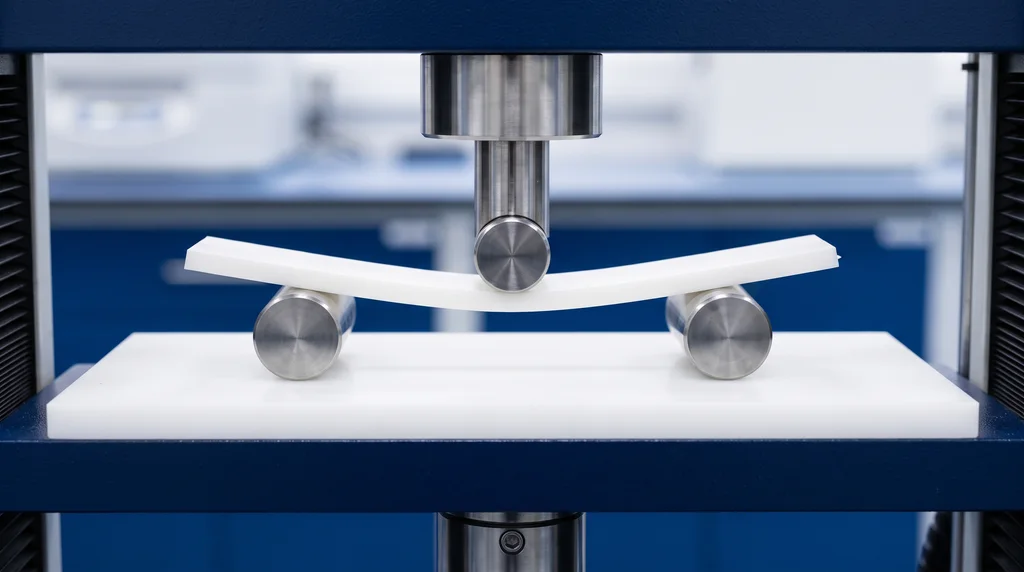
In the photo, a plastic bar in a 3-point flexural test: supported on two rollers, it bends under the central loading nose, and the face toward the supports is the one in tension.
What is the flexural test
In the flexural test, a bar-shaped test specimen rests on two rollers and receives a transverse load from one or two loading noses attached to the crosshead of the universal testing machine. The bar bends: the face on the load side is in compression, the face on the support side is in tension, and between them runs the neutral axis, where the normal stress is zero. According to beam theory, the stress increases linearly from the neutral axis, σ = M·y / I, and is maximum at the faces.
The flexural strength is this maximum stress at the moment of fracture. For brittle materials it is also called the modulus of rupture. The formulas assume a homogeneous, isotropic, linear-elastic material with the same modulus in tension and compression, and they are only valid for small deflections. It is one of the basic mechanical tests, along with the tensile test and the compression test.
What the machine records is the force × midspan deflection curve. Using beam theory formulas, force becomes outer-fiber stress and deflection becomes strain, and three results come from this curve: the flexural strength, at the fracture point; the strain at break; and the flexural modulus, the stiffness of the material, taken from the slope of the initial portion. Brittle materials break while still in the straight portion. Many plastics and ductile metals do not break: the bar simply keeps bending, and the test ends at a strain limit, because beyond it the formulas are no longer valid.
The setup is simple: the bar has no shoulders and does not go into a grip, it just rests on the supports, and forces are usually low. That is why the test serves quality control of batches as well as the development of formulations and composites, the comparison and selection of materials, and the failure analysis of parts that work in bending, such as beams, plates and pavements.
3-point and 4-point bending
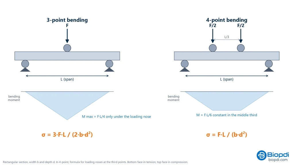
In 3-point bending, the bar rests on two supports separated by the span L, and a single loading nose comes down at midspan. Each support reacts with half the force, and the bending moment increases from the supports to the center, where it reaches F·L/4, exactly under the loading nose. It is the simplest setup and the one used in the plastics standards, ASTM D790 and ISO 178.
In 4-point bending, two symmetrical loading noses apply the load, each with F/2, at the third points of the span or at the limits of the central half. Between the two loading noses the shear force is zero and the moment is constant: this entire section is in pure bending, under the same maximum stress. The diagrams below show both setups, with the applied force and the F/2 reactions at the supports.
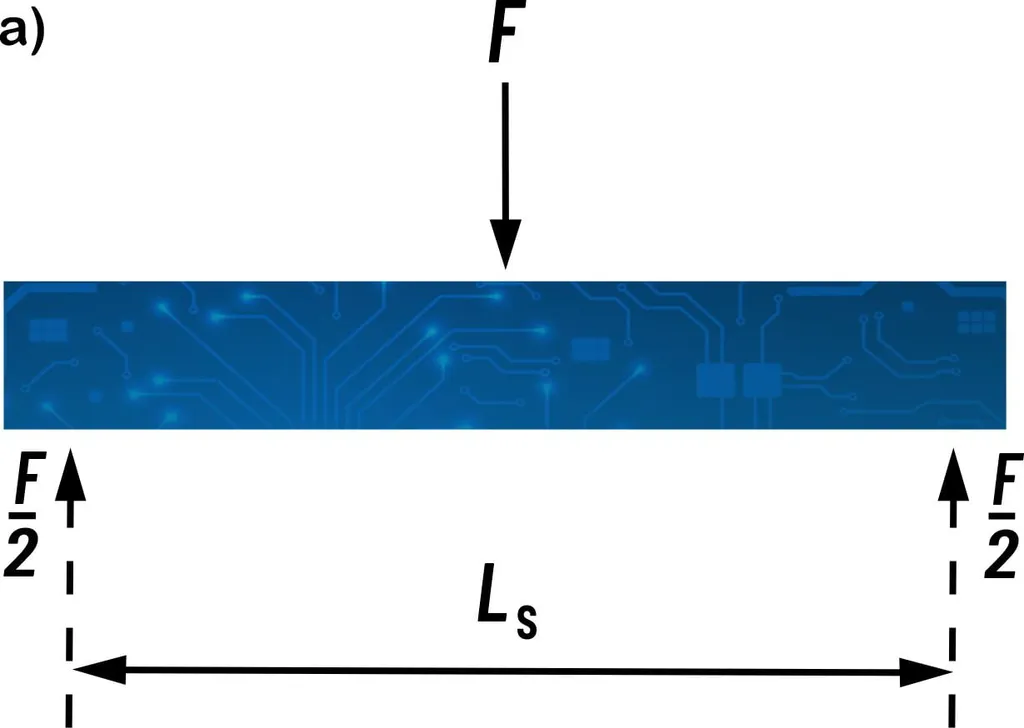
3-point bending: load at midspan
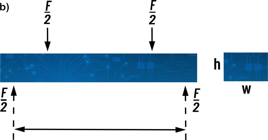
4-point bending: two equal loads and constant moment between them
The difference that matters lies in the bending moment diagram. The diagram below compares the two configurations: in 3-point bending the diagram is triangular, with the peak only under the loading nose; in 4-point bending it is flat between the loading noses. The diagram also shows the flexural stress formula for each, derived in the calculation section.
The table summarizes the differences that matter when choosing between the two:
| Aspect | 3-point | 4-point |
|---|---|---|
| Load | one loading nose at midspan | two symmetrical loading noses (at the third points or in the central half) |
| Bending moment | triangular, maximum only under the loading nose (F·L/4) | constant between the loading noses, no shear force (pure bending) |
| Volume under maximum stress | a narrow band | the entire central section |
| Strength measured in brittle materials | tends to be higher | lower and more representative |
| Where it is used | plastics (D790, ISO 178), composites, quality control | ceramics (C1161), concrete (NBR 12142), plastics (D6272), composites |
Why ceramics and concrete call for 4-point bending. In a brittle material, fracture starts at the largest flaw present in the region under tension. In 3-point bending, only a narrow band under the loading nose receives the maximum stress, the chance of a critical flaw being there is lower, and the strength is overestimated. In 4-point bending, the entire section between the loading noses is under maximum stress and the result better reflects the actual flaws. ASTM C1161, for ceramics, recommends 4-point bending and warns that 3-point strength tends to be much higher.
How to calculate flexural strength
Variables: F is the force (N), L the support span (mm), Li the loading span between the loading noses, b the width, d the depth, D the midspan deflection and m the initial slope of the force × deflection curve (N/mm). Result in MPa.
The formulas come from beam theory. The outer-fiber stress is the bending moment divided by the section modulus, σ = M / W; for a rectangle, W = bd² / 6. In 3-point bending, the maximum moment is F·L/4, and σf = (FL/4) / (bd²/6) = 3FL / (2bd²). In 4-point bending with loads at the third points, each loading nose applies F/2 at L/3 from the nearest support, the moment between the loading noses is F·L/6 and σf = FL / (bd²). By the same theory, the midspan deflection D gives the outer-fiber strain, and the slope m of the initial portion of the curve gives the flexural modulus.
Do not confuse the flexural modulus, which is the stiffness of the material in GPa, with the section modulus W, which is purely the geometry of the cross-section (mm³).
The table brings together the formulas by configuration and by standard:
| Quantity | Formula | Note |
|---|---|---|
| Flexural stress, 3-point | σf = 3FL / (2bd²) | ASTM D790, ISO 178 |
| Flexural stress, 4-point with loads at the third points | σf = FL / (bd²) | NBR 12142, ASTM D6272 |
| Flexural stress, 4-point, general form | σf = 3F(L − Li) / (2bd²) | with Li = L/2: 3FL / (4bd²) |
| Circular cross-section, 3-point | σf = 8FL / (πd³) | d is the diameter |
| Outer-fiber strain | εf = 6Dd / L² | ASTM D790, ISO 178 |
| Flexural modulus (tangent) | Eb = L³m / (4bd³) | ASTM D790 |
| Flexural modulus (chord) | Ef between 0.05% and 0.25% strain | ISO 178 |
| Concrete (NBR 12142) | fct,f = F·ℓ / (b·d²) | fracture in the middle third |
| Mortar (NBR 13279) | Rf = 1.5·Ff·L / 40³ | 4 × 4 × 16 cm prism |
Interactive simulation
Try the test in your browser and watch the results being calculated.
Flexural test specimen
The flexural test specimen is a straight bar, usually with a rectangular cross-section; the circular cross-section also has its own formula. With no shoulders or grips, it is simple to manufacture, but the dimensions are not arbitrary: the standard for each material sets the cross-section, the length and, above all, the span-to-depth ratio. The most common shapes:
- Plastics: 127 × 12.7 × 3.2 mm bar in ASTM D790 and 80 × 10 × 4 mm in ISO 178.
- Ceramics: small bars, a few millimeters in cross-section, such as the 4 × 3 mm bar of ASTM C1161 used in exercise 4, below.
- Concrete: 150 × 150 × 500 mm prism, molded according to ABNT NBR 5738 (the Brazilian standard for molding and curing concrete specimens).
- Mortar: 4 × 4 × 16 cm prism, according to ABNT NBR 13279 (the Brazilian standard for flexural and compressive strength of mortar).
The span-to-depth ratio determines how the bar fails. With a long span relative to the depth, the bending moment dominates and the bar fails in bending, as the formulas assume. With a short span, the shear force gains weight and the bar may fail in shear. That is why D790 and ISO 178 use a span of 16 times the thickness, and high-strength composites, whose interlaminar shear strength is low compared with their flexural strength, call for 32:1 or 40:1.
The bar must also be representative of the material. In composites, fiber orientation changes strength and stiffness; in sheets and plates, so does the direction in which the specimen is cut relative to the rolling direction or molding flow, and it goes into the report. In brittle materials, fracture starts at a flaw on the tension face, so scratches and burrs on that face lower the result: for ceramics, the standard even controls the surface finish.
Flexural test step by step (ASTM D790 and ISO 178)
- Prepare the test specimen to the dimensions in the standard, shown in the previous section, and condition plastics before testing.
- Measure b and d at midspan and use the measured values, not the nominal ones.
- Set the span: 16 times the thickness (51.2 mm for the D790 bar; 64 mm for the ISO bar), or the larger ratio required by the composites standard.
- Position the bar centered on the supports, with the loading nose at midspan.
- Load at the rate specified by the standard. In D790, R = Z·L² / (6d), with Z = 0.01 min⁻¹ in procedure A (1.4 mm/min for the standard bar) or 0.10 min⁻¹ in procedure B (13.7 mm/min), for materials that do not break before 5%. In ISO 178, 2 mm/min.
- Stop at fracture or, in D790, when the outer fiber reaches 5% strain, because beyond that the formulas are no longer valid.
- Calculate the strength, strain and modulus, reporting the standard, the procedure and which modulus was used (tangent, secant or chord).
ASTM D790 and ISO 178 use the same principle, but different test specimens, speeds and modulus calculations: the numbers are not directly comparable.
Flexural test by material
The principle is the same for all materials. What changes is the standard, the configuration, the specimen size and what you look for in the curve.
Plastics
For plastics, 3-point bending according to ASTM D790 or ISO 178 is the test that provides the flexural modulus on datasheets, used to compare the stiffness of grades and formulations. Rigid, brittle plastics such as polystyrene and acrylic break while still in the nearly straight portion of the curve; ductile ones such as polypropylene usually do not break, and the test ends at the strain limit of the standard. The result depends on temperature, humidity and speed, which is why the specimen is conditioned beforehand. For 4-point bending, the plastics standard is ASTM D6272.
Composites
In polymer matrix composites (ASTM D7264, ISO 14125), flexural strength and stiffness depend on the orientation and distribution of the fibers, and fracture can start on the tension face, on the compression face or between plies, through delamination. That is why the span is longer and the failure mode of the bar is recorded, not just the maximum force. The test is used to compare laminates with fibers in different directions and to qualify the manufacturing process.
Ceramics and glass
Ceramics and glass hardly deform plastically and break all at once, while still in the straight portion of the curve. The grip of a tensile test tends to crack them, and bending, with the bar simply supported, gets around the problem. ASTM C1161 uses small bars and recommends 4-point bending, for the reason explained in "3-point and 4-point bending". Since each bar has different flaws, the result varies considerably from one to another, and the lab tests several specimens from the same batch.
Metals
Ductile metals such as steel and aluminum yield and bend without breaking. Past yielding, the stress is no longer proportional to the distance from the neutral axis and the elastic formula no longer applies; that is why flexural strength is not a usual property for steel. In ductile metals, bending appears as the bend test, which checks whether the part bends to a given angle without cracking. In brittle metals such as gray cast iron, bending measures the fracture strength as with other brittle materials.
Concrete
ABNT NBR 12142:2010. A 150 × 150 × 500 mm prism, molded according to NBR 5738, is supported on a 450 mm span and loaded by two forces at the third points, with stress increasing at 0.9 to 1.2 MPa/min, without shocks. The width and depth are measured at the fracture section. With fracture in the middle third, fct,f = F·ℓ / (b·d²). If fracture occurs outside the middle third, within 5% of ℓ from it, fct,f = 3·F·a / (b·d²) is used, where a is the distance from the fracture to the nearest support; farther than that, the test is discarded. It is the strength used in the mix design of concrete pavements.
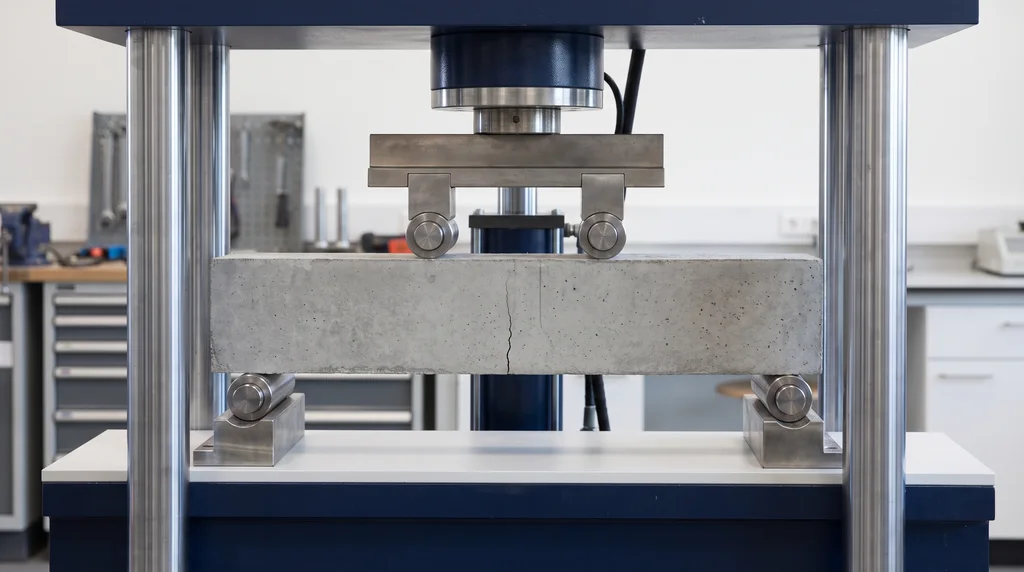
In the photo, a concrete prism after fracture in the 4-point test: the crack opened between the two loading noses, in the middle third, where the moment is maximum and constant and where the standard expects fracture.
The flexural tensile strength is higher than the direct tensile strength of the same concrete. NBR 6118 (the Brazilian standard for the design of concrete structures) relates the two by fct = 0.7·fct,f and, in the absence of testing, estimates the mean direct tensile strength by fct,m = 0.3·fck2/3. Combining the two relations, the estimated flexural tensile strength is about 3.7 MPa for a C25, 4.1 MPa for a C30, 5.0 MPa for a C40 and 5.8 MPa for a C50.
Mortar
ABNT NBR 13279:2005. The 4 × 4 × 16 cm prism is loaded at the center, in 3-point bending, at (50 ± 10) N/s: Rf = 1.5·Ff·L / 40³. The two remaining halves then go to the compression test.
Flexural strength of materials: typical values
The table lists typical values of flexural strength and flexural modulus. Use them to predict the test force and to check that a result is in the expected order of magnitude, not as a replacement for the data sheet of the material being tested.
| Material | Flexural strength (MPa) | Flexural modulus (GPa) |
|---|---|---|
| Polypropylene (PP) | 40 | 1.5 |
| Polystyrene (PS) | 70 | 2.5 |
| PET | 80 | 1 |
| Nylon 6 (PA6) | 85 | 2.3 |
| Polycarbonate (PC) | 90 | 2.3 |
| Acrylic (PMMA) | 100 | 3 |
| Acetal with 30% glass fiber | 150 | 7.5 |
| Soda-lime glass | 69 | |
| Alumina (Al₂O₃) | 275 to 700 | |
| Silicon carbide (SiC) | 100 to 820 | |
| Silicon nitride (Si₃N₄) | 250 to 1,000 | |
| C30 concrete (estimated per NBR 6118, the Brazilian structural concrete standard) | ≈ 4.1 |
Sources: MatWeb (plastics, typical average values) and Callister and Rethwisch, Table 12.5 (ceramics). For plastics, the value varies with the grade, the moisture content (polyamide absorbs water and loses stiffness) and the standard; for ceramics, the wide ranges reflect processing and porosity.
Worked flexural test examples
1. Polycarbonate, ASTM D790. Bar of 127 × 12.7 × 3.2 mm, span of 16 × 3.2 = 51.2 mm, maximum force of 150 N, initial slope of 28.5 N/mm. Stress: σf = 3 × 150 × 51.2 / (2 × 12.7 × 3.2²) = 88.6 MPa. Modulus: Eb = 51.2³ × 28.5 / (4 × 12.7 × 3.2³) ≈ 2.3 GPa. The 5% strain corresponds to a deflection of 6.83 mm, and the procedure A rate is 1.37 mm/min.
2. Concrete, NBR 12142 (Brazilian standard for concrete flexural tensile strength). Prism of 150 × 150 mm, span of 450 mm, maximum force of 33.75 kN with fracture in the middle third: fct,f = 33,750 × 450 / (150 × 150²) = 4.5 MPa. The estimated direct tensile strength is 0.7 × 4.5 = 3.15 MPa.
3. Mortar, NBR 13279 (Brazilian standard for mortar). Prism of 40 × 40 × 160 mm, force of 1,200 N, span of 100 mm: Rf = 1.5 × 1,200 × 100 / 40³ = 2.81 MPa.
4. Alumina, ASTM C1161, 3-point vs. 4-point. Bar of 4 × 3 mm, span of 40 mm, loading span of 20 mm, force of 400 N. In 4-point: σ = 3 × 400 × (40 − 20) / (2 × 4 × 3²) = 333 MPa. With the same force in 3-point: σ = 3 × 400 × 40 / 72 = 667 MPa. For the same force, the moment in 3-point bending is twice as large.
5. Round bar, 3-point. Polymer bar 10 mm in diameter, span of 100 mm, force of 150 N: σ = 8 × 150 × 100 / (π × 10³) = 38.2 MPa.
Flexural test standards
The standard depends on the material and, for plastics and composites, also on the chosen configuration. The table lists the most widely used ones, with the configuration and the current edition:
| Standard | Application | Configuration | Edition |
|---|---|---|---|
| ASTM D790 | reinforced and unreinforced plastics | 3-point, 16:1 span | D790-25 |
| ASTM D6272 | plastics | 4-point | D6272-25 |
| ISO 178 | plastics | 3-point, 16:1 span | 2019 |
| ASTM C1161 | advanced ceramics | 3-point and 4-point (recommends 4-point) | C1161-18 (reapproved 2023) |
| ASTM D7264 | polymer matrix composites | 3-point and 4-point, 32:1 span | D7264-26 |
| ISO 14125 | fiber-reinforced composites | 3-point and 4-point | 1998 (2011 amendment) |
| ABNT NBR 12142 | concrete, flexural tensile strength (Brazil) | 4-point, third-point loading | 2010 (confirmed 2024) |
| ABNT NBR 13279 | mortar (Brazil) | 3-point | 2005 |
| ABNT NBR 7190-3 | timber (Brazil) | static bending | 2022 |
ASTM D3039, which shows up in searches alongside flexure, is a tensile test standard for composites, not a flexural one. Bend test standards (ASTM E290, ISO 7438, NBR 6153, the Brazilian bend test standard) are also left out of the table: the bend test, covered under "Metals", gives a pass or fail result, not a strength. Rotating bending fatigue, which measures life under cyclic loading, is covered in fatigue testing.
Common mistakes in flexural testing
- Wrong span. Using a fixed span instead of 16 times the measured thickness changes the result.
- Span too short. Shear dominates and the bar fails in shear, not in bending. Intentional shear failure is a different test, the short-beam test, explained in shear testing.
- Large deflections. The formulas assume small angles; that is why D790 stops at 5% strain.
- Indentation under the loading nose in soft plastics and foams: the crosshead displacement overestimates the deflection and underestimates the modulus. Use a deflectometer under the bar.
- Modulus from the crosshead without compensating for system compliance.
- Comparing 3-point and 4-point results, or D790 with ISO 178. Always report the standard and the procedure.
- For concrete, ignoring where the fracture occurred. Outside the middle third the formula changes; too far out, the test is discarded.
- Assuming the moment is constant in 3-point bending. It is triangular; the constant-moment region only exists in 4-point bending.
Flexural testing machine
On a universal testing machine, the test uses a flexure fixture with two roller supports with adjustable span and one or two loading noses attached to the crosshead. The load cell measures the force, a deflectometer or the corrected displacement measures the deflection, and the software converts force × deflection into stress × strain and calculates the modulus. The Biopdi line of universal testing machines performs 3-point and 4-point flexural tests, with flexure fixtures of 10 kN, 50 kN and 300 kN. The panel below shows the machine, the role of each part in the flexural test and the fixtures used.
The universal testing machine in the flexural test
The M2 line has single-column models, from 200 N to 10 kN, and dual-column models, from 5 kN to 1,000 kN. Each part of the machine has a role in the test:
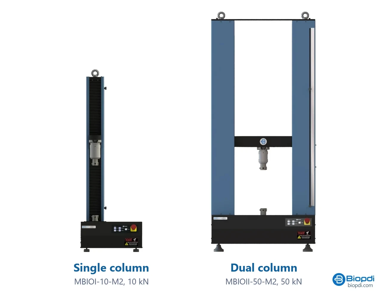
- Moving crosshead lowers the loading nose at the rate set by the standard
- Load cell small capacity, for low forces
- Flexure fixture 3-point or 4-point, adjustable span
- Deflectometer measures deflection at midspan
- BioLab software flexural strength and flexural modulus
- Control panel and emergency stop positions and stops the test
Fixtures for the flexural test
The fixtures below are mounted on the same machine, depending on the specimen and the standard:
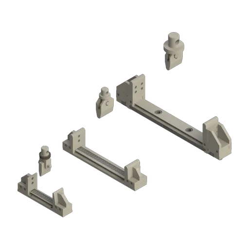
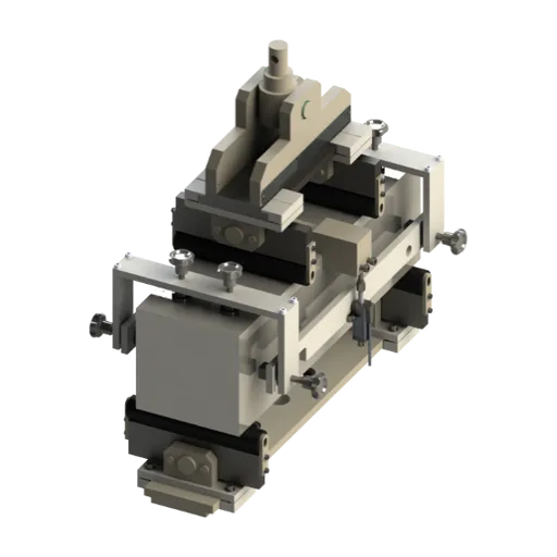
The rule is to size the load cell to the expected force, because many flexural specimens fail at low force: a PP bar per ISO 178 fails at about 67 N, a polycarbonate bar per D790 at about 150 N, an alumina bar at about 360 N, a mortar prism at about 1.3 kN and a 150 mm concrete prism at about 45 kN. The table below indicates the model by force range:
| Application | Typical force | Biopdi model |
|---|---|---|
| Plastics (D790, ISO 178), small ceramics, mortar | tens of N to 2 kN | MBIOI-10-M2 (2 to 10 kN) |
| Composites, timber, concrete prisms | up to about 50 kN | MBIOII-50-M2 (5 to 50 kN) |
| Beams and larger parts | hundreds of kN | MBIOII-300-M2 or compression testing machine |
Flexural test video
Flexural test on a Biopdi universal testing machine.
Other tests and technical references
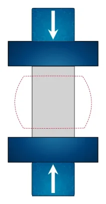
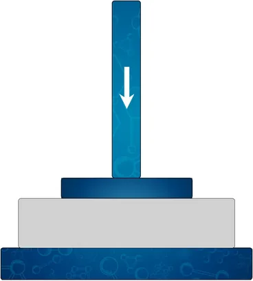
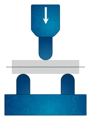
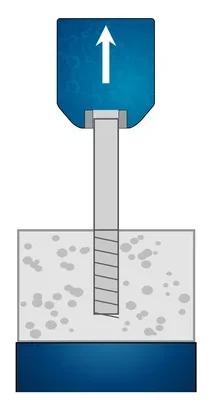
Tests performed on the Biopdi universal testing machine






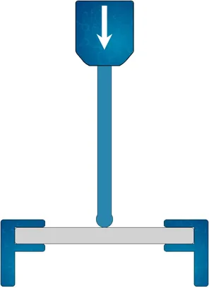
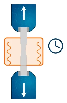


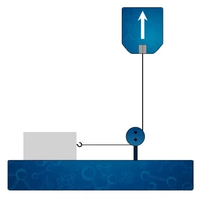
Related technical references
ASTM D790: three-point flexural test of plastics (procedures A and B, support span and calculations)
ASTM D790-25 measures the flexural strength and flexural modulus of plastics using a bar on two supports loaded at midspan. The support span is 16 times the thickness. The strain rate is 1%/min (procedure A) or 10%/min (procedure B), and the test runs until the specimen breaks or reaches 5% strain. Covers the crosshead speed R = ZL²/6d, the formulas, the large-deflection correction, a comparison with ISO 178 and D6272, and worked examples.
Compression test: what it is, how to calculate it, concrete (NBR 5739 and fck) and standards
A compression test shortens a specimen until it fractures or yields. Learn to calculate compressive strength, plus NBR 5739, concrete fck and standards.
Crush test: ECT, FCT, RCT and BCT
The crush test compresses corrugated board until it collapses. See ECT, FCT, RCT, CMT and BCT, formulas, McKee, 32 ECT in kN/m, standards and examples.
Frequently asked questions
What is a flexural test?
It is the test in which a bar resting on two supports receives a transverse load until it fractures or reaches a limit strain. It measures flexural strength and flexural modulus. It is the preferred test for brittle materials such as ceramics, concrete and glass.
What is a 3-point flexural test?
The bar rests on two supports and the load is applied by a loading nose at midspan. The bending moment is maximum under the loading nose, and the flexural strength is σf = 3FL / (2bd²), per ASTM D790 or ISO 178.
What is the difference between 3-point and 4-point bending?
In 4-point bending, the moment is constant between the two loading noses, with no shear force, and a larger region is under the maximum stress. That is why, for brittle materials, the strength measured in 4-point bending is lower and more realistic, and the ceramics and concrete standards use 4-point bending.
What is bending theory?
It is Euler-Bernoulli beam theory: plane sections remain plane, stress varies linearly from the neutral axis and equals σ = M·y / I, maximum at the faces. It assumes a homogeneous, isotropic, linear-elastic material and small deflections.
What is the standard for the flexural tensile strength test?
For concrete, ABNT NBR 12142:2010 (the Brazilian standard), with prisms loaded at the third points of the span: fct,f = F·ℓ / (b·d²). For mortar, ABNT NBR 13279:2005 (Brazil), with 4 × 4 × 16 cm prisms.
What is flexural strength?
It is the maximum stress in the outer fiber of the bar at the moment of fracture, calculated with the flexure formula. For brittle materials it is also called the modulus of rupture. For polycarbonate it is around 90 MPa; for C30 concrete, around 4 MPa.
What is the section modulus in bending?
It is a geometric property of the cross section, W = I / c, equal to bd² / 6 for a rectangle, with σ = M / W. Do not confuse it with the flexural modulus, which is the stiffness of the material in GPa.
What is normal bending stress?
It is the tensile or compressive stress caused by the bending moment, σ = M·y / I. It is zero at the neutral axis and maximum at the faces: tension on the convex face and compression on the concave face.
How do you calculate the flexural modulus?
In ASTM D790, from the initial slope m of the force × deflection curve: Eb = L³m / (4bd³). In ISO 178, from the chord between 0.05% and 0.25% strain. A polycarbonate bar gives about 2.3 GPa.
What is the span in the ASTM D790 test?
Sixteen times the bar thickness: 51.2 mm for the standard 3.2 mm bar. For high-strength composites, 32:1 or 40:1 is used to avoid shear failure.
Is a flexural test the same as a bend test?
No. The flexural test is quantitative and gives the strength in MPa. The bend test is qualitative: the part is bent to a given angle and checked for cracks, to assess ductility.
What is the flexural strength of concrete?
Typically 4 to 6 MPa for concretes with fck of 30 to 50 MPa. Per NBR 6118 (the Brazilian structural concrete standard), the direct tensile strength is 0.7 times the flexural tensile strength, and the mean tensile strength can be estimated as 0.3·fck^(2/3).