
The compression test applies an increasing axial force to shorten a test specimen and measure its strength and deformation. Compressive strength is the maximum force divided by the original cross-sectional area, σ = F / A0, in MPa. For concrete, under ABNT NBR 5739:2018 (the Brazilian standard for compression testing of concrete cylinders), fc = 4F / (πD²): a 10 × 20 cm cylinder that fails at 236 kN has 30.0 MPa.
It is the test that approves the concrete on a construction site, measures the compressive yield of metals and qualifies plastics, foams, wood, springs and packaging. This guide covers what the test measures, the test specimen, the curve of each type of material, the formulas, the NBR 5739 procedure step by step, what fck is and how to calculate it, compression testing of other materials, solved exercises, the standards and how to choose the machine.
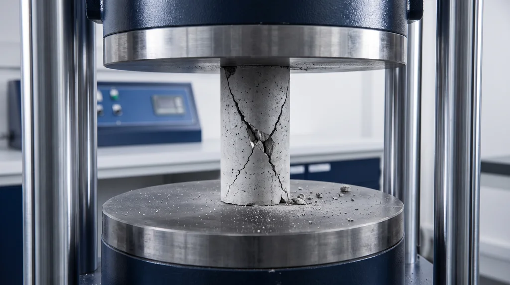
The photo shows a concrete cylinder broken between the platens of the press: the inclined cracks form cones, the typical failure pattern of concrete in this test.
What is a compression test
In a compression test, the specimen sits between two parallel platens, and the machine moves them together at a controlled rate. Force and shortening are recorded until failure or until a deformation limit set by the standard. It is the opposite of the tensile test, which pulls the specimen apart, and it is one of the basic mechanical tests.
The force and shortening records give the mechanical properties of the material in compression:
- Compressive strength: the highest stress the material withstands before failing, that is, the maximum force divided by the original area, in MPa. Because it is a stress and not a force, it allows specimens of different sizes to be compared.
- Compressive yield strength: the stress at which permanent deformation begins. This is the value reported for ductile metals.
- Modulus of elasticity: the slope of the initial straight portion of the curve. It measures stiffness: the higher the modulus, the less the material shortens under the same stress.
- Elastic and plastic deformation: elastic deformation disappears when the load is removed; plastic deformation remains. The curve shows where one ends and the other begins.
- Failure mode: whether the specimen fails in cones, along an inclined plane, by shattering, or simply flattens. In concrete, the failure type is part of the result and points to preparation defects.
These values are used to design columns, foundations and compression members, to choose between materials, to control the quality of batches and to follow the development of new formulations. The test also measures how temperature, moisture or aging change strength, and it is used to validate numerical models, such as finite element models, by comparing the measured curve with the calculated one. It is a destructive test: the specimen comes out broken or crushed, so it is taken from a representative sample of the batch.
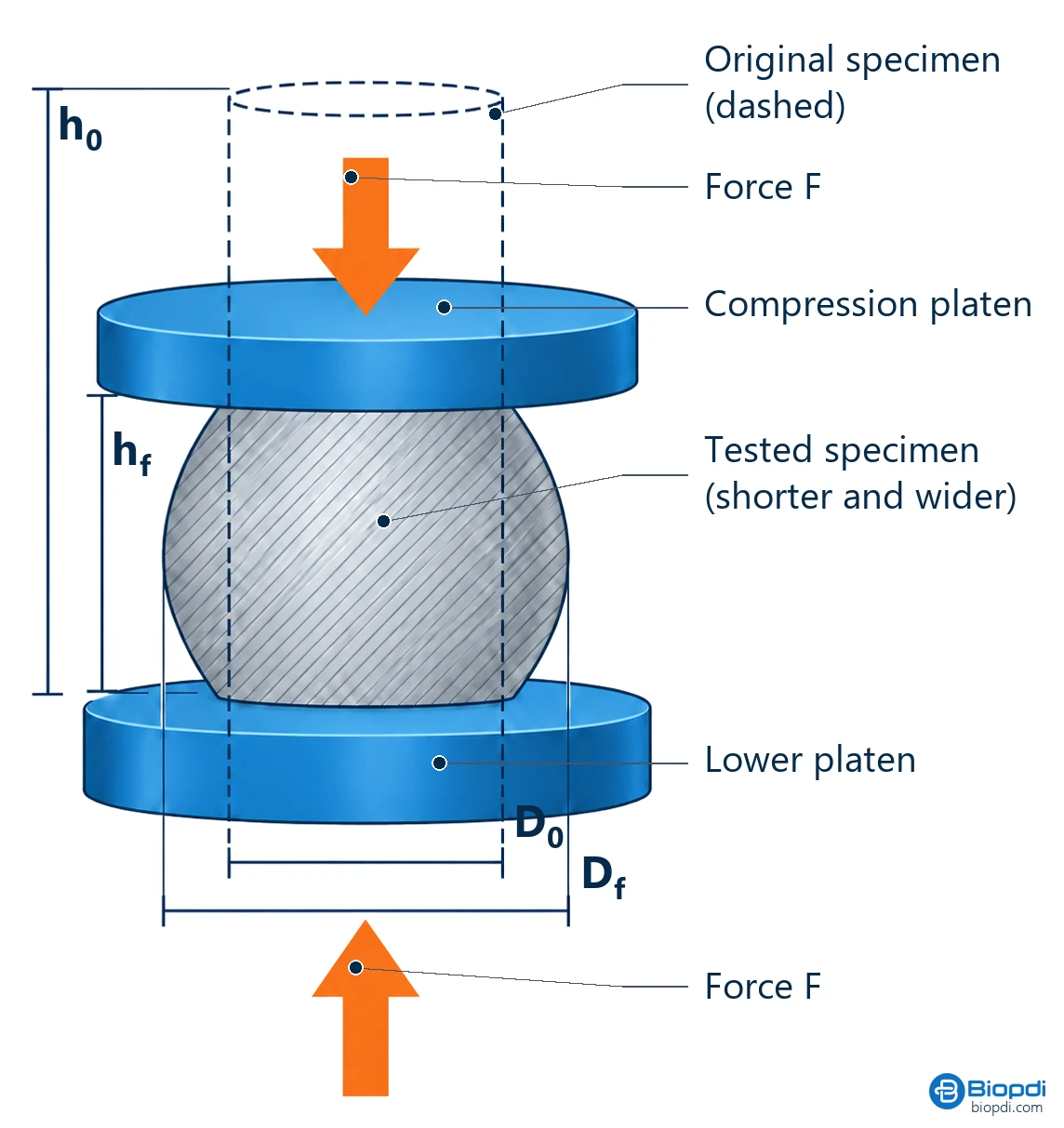
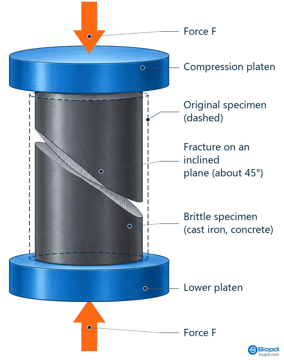
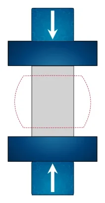
Compressive strength only makes sense for materials that fail at a clear force peak, such as concrete, cast iron and ceramics, which are brittle. Ductile metals do not fracture in compression: they flatten and barrel, that is, they shorten and bulge in the middle, taking a barrel shape. For these, ASTM E9 requires reporting the compressive yield strength or the stress at a specified strain, because a "strength" would depend only on how far the specimen was crushed. The two diagrams below show this difference: on the left, the specimen that shortens and widens, with the initial and final heights and diameters; on the right, the brittle material that fractures along an inclined plane between the platens.
Compression test diagram: the specimen shortens and widens
Compression of a brittle material: fracture along an inclined plane
Test specimen for compression testing
The test specimen is a sample with a shape and dimensions set by the material standard, so that different laboratories reach comparable results. The cylinder is the most common shape; plastics, wood and foams also use prisms and cubes. Three precautions apply to all of them:
- Height-to-diameter ratio (h/d). A tall, slender specimen tends to buckle, that is, to bend sideways before failing in compression. A very short specimen is more affected by friction with the platens, which prevents the end faces from expanding, and it fails at a higher force than the material actually withstands. That is why each standard sets the h/d: for concrete it is 2, and shorter specimens have their force corrected.
- Flat, parallel end faces perpendicular to the axis. Otherwise the load concentrates on one side and the specimen fails early. The faces are machined or ground; for concrete, capping (a thin layer that levels the face) or an unbonded neoprene pad is also used.
- Measured dimensions, not nominal ones. The area used in the calculation comes from the diameter or sides measured on the specimen itself.
The specimen must be free of cracks, voids and burrs, and it is identified with the material, the batch and the age or test condition. The dimensions required by each standard are given in the sections on concrete and on other materials, further on.
Stress-strain curve in compression
During the test, the software divides the force by the original area and the shortening by the original height and plots the stress-strain curve. Each class of material produces a curve of a different shape, and that shape decides what is reported. The graph below compares three cases: the ductile metal, whose curve rises without a peak because it flattens without breaking; concrete, which is brittle, reaches a peak and drops when it fails; and rigid foam, which forms a plateau after the elastic portion while the cells collapse.
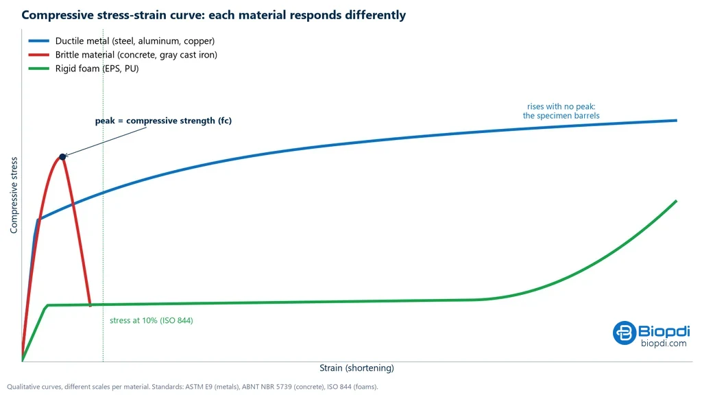
In metals, the initial portion is straight, as in tension, and yield is read by the 0.2% offset method, explained in "How to calculate" just below. In concrete and other brittle materials, the value of interest is the peak. In foam, which often has no peak, the stress at a fixed strain is reported. The table summarizes, material by material, how it deforms and fails, what is reported and the standard:
| Material | How it deforms and fails | What is reported | Standard |
|---|---|---|---|
| Ductile metals (steel, aluminum, copper) | barrels, does not fracture | 0.2% yield strength, modulus, curve | ASTM E9 |
| Gray cast iron | shear fracture along an inclined plane | maximum strength | ASTM E9 |
| Concrete | cones and shear (types A to G) | fc and the batch fck | ABNT NBR 5739 |
| Technical ceramics | shattering | maximum strength | ASTM C773 (whiteware ceramics) |
| Rigid plastics | yielding or crushing | strength, yield and modulus | ASTM D695, ISO 604 |
| Rigid foams | cell collapse | stress at 10% strain | ISO 844, ASTM D1621 |
| Wood | fiber crushing | fc0 parallel to the grain, at 12% moisture content | ABNT NBR 7190-3 (Brazilian timber test standard) |
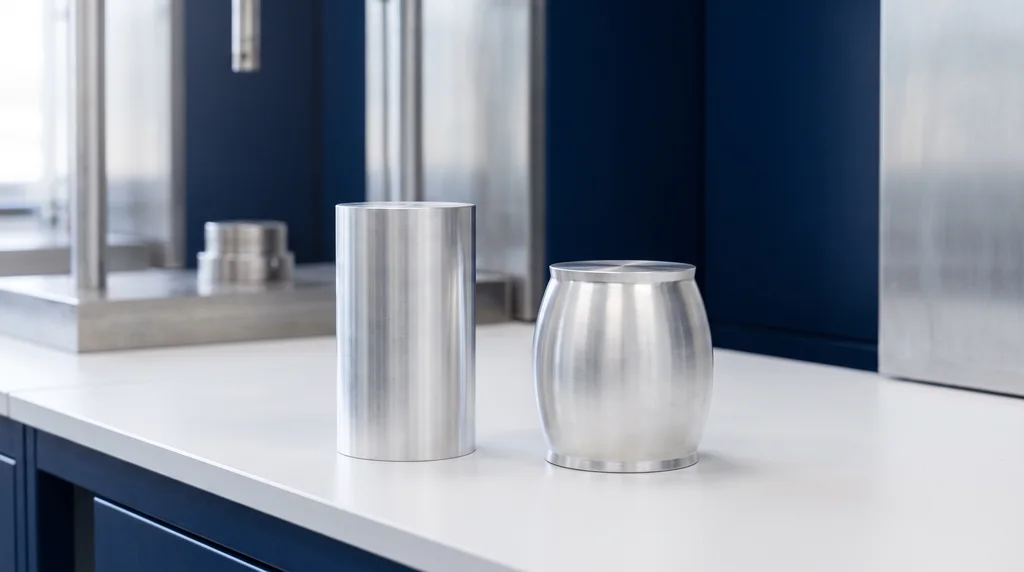
Why metals barrel. Friction with the platens keeps the end faces from expanding, while the middle of the specimen widens freely. The effect increases the apparent force; it is reduced with a lubricant on the faces (PTFE or paraffin) and with the height-to-diameter ratio set by the standard. The photo below shows the result on an aluminum cylinder: on the left, the original specimen; on the right, the same specimen after compression, shorter, wider in the middle and without a single crack.
Why brittle materials fail at an angle. In uniaxial compression, the maximum shear stress acts on planes at about 45° to the axis. Friction with the platens changes this angle, and in concrete it produces the characteristic cones.
Why concrete and cast iron are stronger in compression than in tension. Microcracks and graphite flakes open cracks when pulled and tend to close when compressed. Class 30 gray cast iron has about 752 MPa in compression versus 207 MPa in tension; alumina, about 2,100 MPa in compression versus 345 MPa in flexure; a concrete with 30 MPa compressive strength has a mean tensile strength of only 2.9 MPa according to ABNT NBR 6118 (the Brazilian code for the design of concrete structures), close to 10% of that.
How to calculate compressive strength
The calculation follows the same logic as in tension: stress is the force divided by the original area, and strain is the shortening divided by the original height. The modulus of elasticity requires measuring the shortening on the specimen itself, with a compressometer, which is an extensometer set up for compression; the platen displacement includes the deformation of the machine and would give a modulus lower than the real one. The table gathers the formulas:
| Quantity | Formula | Unit and note |
|---|---|---|
| Compressive stress | σ = F / A0 | MPa (N/mm²); A0 is the original area |
| Strength of a concrete cylinder | fc = 4F / (π·D²) | MPa, to 3 significant figures (NBR 5739) |
| Strain | ε = ΔL / L0 | shortening over the original height |
| Modulus of elasticity in compression | E = Δσ / Δε in the linear portion | GPa; requires a compressometer or extensometer |
| Compressive yield strength (metals) | 0.2% offset, as in tension | MPa (ASTM E9) |
Offset yield is read by drawing a line parallel to the straight portion of the curve, shifted 0.2% along the strain axis: where it crosses the curve is the yield strength. The fck formulas, which deal with the set of results from a batch of concrete, are in the section on fck, further on.
Example. A concrete specimen with a mean diameter of 100.2 mm failed at 248.6 kN at 28 days. The area is π × 100.2² / 4 = 7,885 mm², so fc = 248,600 / 7,885 = 31.5 MPa.
Concrete compression test: NBR 5739 step by step
ABNT NBR 5739:2018 is the Brazilian standard for testing cylindrical concrete specimens molded according to NBR 5738, and cores, which are cylinders drilled from the finished structure according to NBR 7680-1. On site, specimens are molded from the delivered concrete, cured and broken at a defined age, and each result goes into the batch control, covered in the section on fck. This control works with samples: under NBR 12655 (the Brazilian standard for concrete preparation, control and acceptance), each sample consists of two specimens from the same batch, tested at the same age, and the higher of the two results counts.
- Test specimen. A 10 × 20 cm or 15 × 30 cm cylinder, molded according to NBR 5738. The height-to-diameter ratio can never exceed 2.06; below 1.94, the force is corrected (table right after the steps).
- Curing. Moist or saturated until the test age: in a moist room at 23 ± 2 °C with humidity above 95%, or in a saturated calcium hydroxide solution, after at least 24 h in the molds.
- End preparation. Grinding, capping or an unbonded device (neoprene). Poorly prepared ends cause type F and G failures.
- Dimensions. Caliper with 0.1 mm resolution; diameter as the mean of two perpendicular measurements at mid-height.
- Age. The reference is 28 days, with a tolerance of ± 24 h. Specimens are also tested at 24 h (± 0.5 h), 3 days (± 2 h), 7 days (± 6 h), 63 days (± 36 h) and 91 days (± 48 h).
- Machine. Calibrated to ISO 7500-1 (ABNT NBR ISO 7500-1 in Brazil) at least every 12 months, with a range such that failure falls within the calibrated interval. The specimen is centered on the platen.
- Loading. Continuous and without shock, at 0.45 ± 0.15 MPa/s, which gives about 3.5 kN/s for the 10 × 20 and 8.0 kN/s for the 15 × 30. Loading stops only when the force drop indicates failure.
- Calculation. fc = 4F / (πD²), in MPa, to three significant figures.
- Failure type. Record the type, from A to G.
The correction compensates for the effect described in the section on the test specimen: a shorter cylinder fails at a higher force. The factor reduces the measured force to what a cylinder with h/d = 2 would have given:
| h/d | 2.00 | 1.75 | 1.50 | 1.25 | 1.00 |
|---|---|---|---|---|---|
| Force correction factor (NBR 5739, Table 2) | 1.00 | 0.98 | 0.96 | 0.93 | 0.86 |
Failure types (Annex A of NBR 5739). A: conical, and conical with the cone 25 mm away from the cap. B: conical and split, or conical with more than one split. C: columnar with cone formation. D: conical and sheared. E: sheared. F: fractures at the top or bottom, below the cap. G: similar to F, with fractures near the top. When the specimens of a single sample show high scatter, the failure is usually type F or G, a sign of a molding or end-preparation defect.
In the United States, ASTM C39 applies, with a loading rate of 0.25 ± 0.05 MPa/s, about half the Brazilian rate. Results obtained under the two standards should not be compared without care.
fck: what it is, formula and what fck 30 MPa means
Three symbols are easily confused. fc is the result of a single test specimen. fcm is the mean of the results. fck is the characteristic strength: the value with a 95 % probability of being exceeded at 28 days. The difference between the mean and fck depends on how much the results vary, measured by the standard deviation sd; the 1.65 in the formulas is the 5 % quantile of the normal distribution.
- In mix design (NBR 12655, the Brazilian standard for concrete preparation, control and acceptance): fcm = fck + 1.65·sd. With no history, the standard deviation is set by the preparation condition: 4.0 MPa (A), 5.5 MPa (B) or 7.0 MPa (C). For fck 30 MPa, the target mean is 36.6, 39.1 or 41.6 MPa.
- In lot control (20 or more samples): fck,est = fcm − 1.65·sd. The lot is accepted if fck,est ≥ fck.
- fck 30 MPa means the concrete was specified so that no more than 5 % of the 28-day results fall below 30 MPa.
The chart below shows this distribution for an fck 30 MPa concrete designed under condition A: the results are distributed around the mean of 36.6 MPa, and only the 5 % tail falls below 30 MPa.
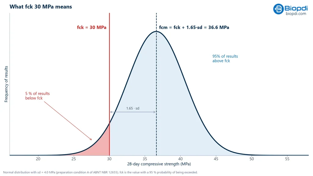
The most common mistake is comparing the mean with fck. A lot of 24 samples with a mean of 34.0 MPa and a standard deviation of 2.5 MPa has fck,est = 34.0 − 1.65 × 2.5 = 29.9 MPa: it does not meet an fck of 30 MPa, even though the mean is 4 MPa higher. fck also names the strength classes: under NBR 8953 (the Brazilian standard for concrete strength classes), the number after the C is the fck in MPa, and group I classes range from C10 to C50. C20 is the minimum for reinforced concrete and C25 for prestressed concrete, under NBR 6118 (the Brazilian standard for the design of concrete structures). Try the numbers in the calculator below.
Interactive simulation
Try the test in your browser and watch the results being calculated.
Compression testing of metals, plastics, ceramics and other materials
Outside concrete, the standard, the test specimen and what is reported change with the material.
Metals (ASTM E9). The test is used on structural steel, aluminum and titanium alloys, among others. The standard provides short, medium and long cylindrical specimens; to measure the strength of high-strength materials, the best length-to-diameter ratios are 1.5 and 2.0. The risks are buckling, in a slender or misaligned specimen, and barreling. A spherically seated upper platen, which tilts to follow the specimen face, compensates for small lack of parallelism. Structural steel has a compressive yield strength practically equal to its tensile yield strength, 250 to 500 MPa in common steels.
Plastics (ASTM D695 and ISO 604). D695 uses a 12.7 × 12.7 × 25.4 mm prism or a 12.7 × 25.4 mm cylinder at 1.3 mm/min; ISO 604 uses 10 × 10 × 4 mm. The two do not give comparable numbers, because geometry and speed differ. As in tension, the result for plastics depends on temperature and humidity, and the specimen is conditioned before the test.
Ceramics. Alumina, silicon nitride and other technical ceramics fail all at once, shattering, with no plastic deformation, and the maximum strength is reported. Since any misalignment concentrates stress in a material that does not yield to relieve it, face parallelism is critical. In porous ceramics, used in filters and catalyst supports, strength drops as porosity increases.
Composites. In carbon or glass fiber composites, compressive strength depends on fiber direction, so the test is performed in the directions that matter for the design. Thin specimens tend to buckle, and the result also changes with temperature and humidity.
Rigid foams (ISO 844, ASTM D1621 and EN ISO 29469, which replaced EN 826). Since many have no peak, the standard requires reporting the stress at 10 % strain. EPS insulation falls in the range of 100 to 500 kPa, depending on density.
Wood (ABNT NBR 7190-3, the Brazilian standard for timber testing). Strength parallel to the grain is measured at 12 % moisture content; in species used in structures, it is typically between 30 and 70 MPa.
Components. Springs, packaging, corrugated board and plastic pipes are also tested in compression, with platens, measuring force at a defined displacement. Corrugated board and boxes have their own tests (ECT, FCT, RCT and BCT), covered in the article on the crush test; flexible mattress and seat foams are evaluated by indentation force, in the IFD test.
Unconfined compression and triaxial testing of soils are a different family of tests, with their own standards; see triaxial test.
Axial compression and diametral compression
In axial compression, the cylinder stands upright and compressive strength is measured (NBR 5739). In diametral compression, the "Brazilian test" of ABNT NBR 7222:2011 (equivalent to ASTM C496), the cylinder lies on its side and the load along a generatrix produces tension on the diametral plane: fct,sp = 2F / (π·d·L), at 0.05 ± 0.02 MPa/s. A 10 × 20 C30 concrete cylinder that breaks lying down at 100 kN has 3.18 MPa of indirect tensile strength; standing upright, it would need 236 kN to reach 30 MPa.
Solved compression test exercises
1. Core with low h/d. A core 100 mm in diameter and 175 mm high (h/d = 1.75) failed at 200 kN. Since h/d < 1.94, the force is multiplied by 0.98: 196.0 kN. fc = 4 × 196,000 / (π × 100²) = 25.0 MPa. Without the correction, it would be 25.5 MPa.
2. Mix design. For fck = 30 MPa under condition B (sd = 5.5 MPa): fcm = 30 + 1.65 × 5.5 = 39.1 MPa.
3. Metal, ASTM E9. Steel specimen of 12.7 × 25.4 mm (A0 = 126.7 mm²). In the linear region, the force went from 5 kN to 25 kN while the compressometer read from 0.000197 to 0.000986 strain. Stresses: 39.5 and 197.3 MPa. E = (197.3 − 39.5) / (0.000986 − 0.000197) ≈ 200 GPa. The 0.2 % offset yield occurred at 40.0 kN: σe = 40,000 / 126.7 = 316 MPa. As the test continues, the specimen barrels and the force rises with no peak.
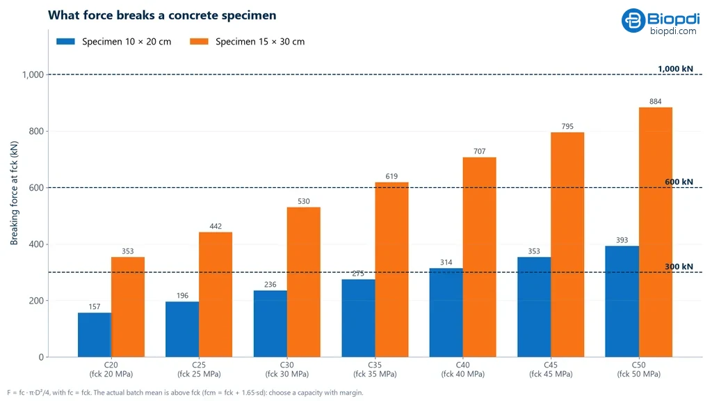
4. Machine capacity. A lab breaks 15 × 30 cylinders up to C40, with a mix design mean of 46.6 MPa. The expected force is 46.6 × 17,671 mm² = 823 kN. A 600 kN machine will not do; a 1,000 kN one will. For the 10 × 20 cylinder of the same class, the force is 366 kN, and 600 kN is more than enough.
Common mistakes in the compression test
- Citing the old NBR 5739. The current edition is from 2018.
- Non-parallel or poorly prepared ends. They concentrate stress and produce type F and G fractures.
- Off-center specimen. It causes bending and lowers the result.
- Wrong loading rate. Loading too fast overestimates strength.
- Forgetting the h/d correction below 1.94, or testing above 2.06.
- Age outside the tolerance (28 days ± 24 h).
- Confusing fc, fcm and fck. Comparing the mean with fck accepts lots that do not comply.
- Confusing slump with strength. "Slump 12 ± 2" is the slump of fresh concrete, 100 to 140 mm: it measures consistency, not strength.
- Reporting the "ultimate strength" of a ductile metal. It does not exist: the yield strength is reported.
- Measuring the modulus from platen displacement. It includes machine deformation and underestimates the modulus.
Compression test standards
The standard depends on the material and, for concrete, also on the stage: molding, testing, lot control and classification each have their own standards. The table lists the most widely used:
| Standard | Application | Edition |
|---|---|---|
| ABNT NBR 5739 | concrete, cylindrical specimens | 2018 |
| ABNT NBR 5738 | molding and curing of specimens | 2015 |
| ABNT NBR 12655 | preparation, control and acceptance of concrete (fck) | 2022 |
| ABNT NBR 8953 | concrete strength classes | 2015 |
| ABNT NBR 7680-1 | cores drilled from the structure | 2015 |
| ABNT NBR 7222 | splitting tensile strength (diametral compression) | 2011 |
| ASTM C39/C39M | concrete (USA) | |
| ASTM E9 | metals | E9-19 (reapproved 2025) |
| ASTM D695 and ISO 604 | rigid plastics | ISO 604:2002 |
| ISO 844, ASTM D1621, EN ISO 29469 | rigid foams (EN ISO 29469:2022 replaced EN 826, withdrawn) | ISO 844:2026 |
| ABNT NBR 7190-3 | wood | 2022 |
| ABNT NBR ISO 7500-1 | machine calibration (ISO 7500-1) | 2023 |
Compression testing machine: press or universal testing machine
The compression press is dedicated: high capacity and compression only, ideal for routine concrete testing. The universal testing machine with compression platens also performs tensile, flexural and shear tests, with speed control and extensometry, and is the choice for labs that also test steel, plastics or wood.
In both cases the parts are the same: a rigid frame, which must not deform along with the specimen; the drive system that brings the platens together at a controlled speed; the load cell, which measures force; strain measurement, by a compressometer on the specimen or by corrected crosshead displacement; and the software, which controls the test, plots the curve and issues the report. The Biopdi universal testing machine is electromechanical: a motor drives the screws that move the crosshead.
The capacity must cover the actual mean of the lot with margin, not just the fck, and specimen size matters as much as the class: the 10 × 20 cylinder requires about 44 % of the force of the 15 × 30 for the same strength. The chart below shows the force that breaks both cylinders in each class, from C20 to C50, compared with capacities of 300, 600 and 1,000 kN.
The panel below shows the universal testing machine, the role of each part in the compression test and the platens used.
The universal testing machine in the compression test
The M2 line has single-column models, from 200 N to 10 kN, and dual-column models, from 5 kN to 1,000 kN. Each part of the machine has a function in the test:
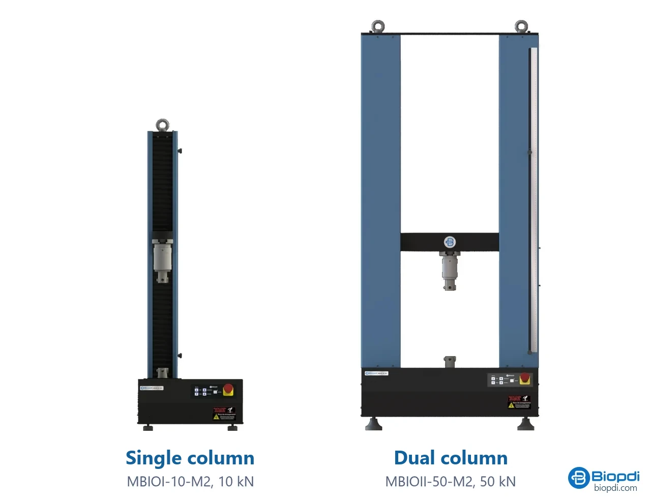
- Moving crosshead brings the platens together at the rate set by the standard
- Load cell measures force, class 1
- Compression platens flat, with a spherical seat for concrete
- Strain extensometer or corrected crosshead travel
- BioLab software strength (F/A), curve and report
- Control panel and emergency stop positions and stops the test
Fixtures for the compression test
The fixtures below are mounted on the same machine, according to the specimen and the standard:
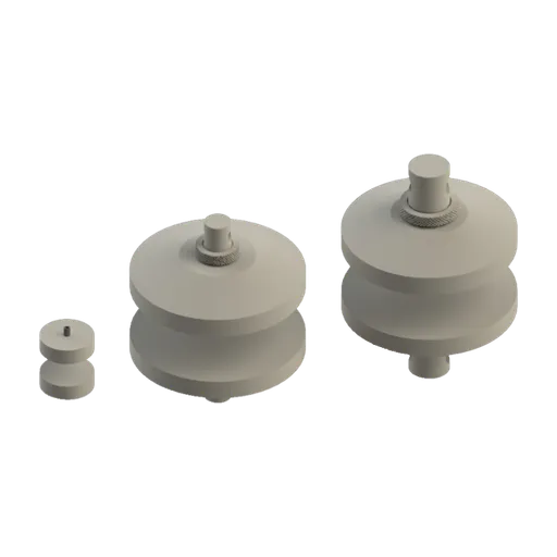
The table links each application to the force range and the Biopdi equipment:
| Compression application | Range | Biopdi equipment |
|---|---|---|
| Foams, small springs, light packaging | 200 N to 10 kN | MBIOI-1P-M2 and MBIOI-10-M2 |
| Plastics (D695), wood, small metal parts | 5 to 50 kN | MBIOII-50-M2 |
| Concrete 10 × 20 up to C25 (at C30, only the mean fits) | 300 kN | MBIOII-300-M2 |
| Concrete 10 × 20 up to C50; 15 × 30 up to about C30 | 600 kN | MBIOII-600-M2 |
| Concrete 15 × 30 of high classes | 1,000 kN | MBIOII-1000-M2 |
| Dedicated routine compression testing | on request | Electric and hydraulic concrete compression testing machine |
Operating details in universal testing machine. For soils, Biopdi offers the CBR and Marshall test press.
Compression test videos
Compression tests on Biopdi universal testing machines, including spring compression on the portable version.
Other tests and technical references
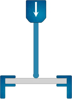
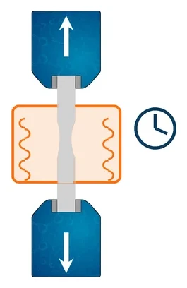
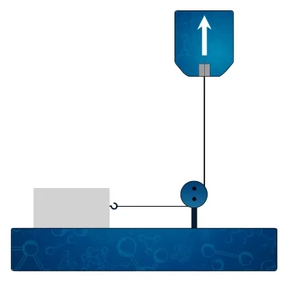
Tests performed on the Biopdi universal testing machine


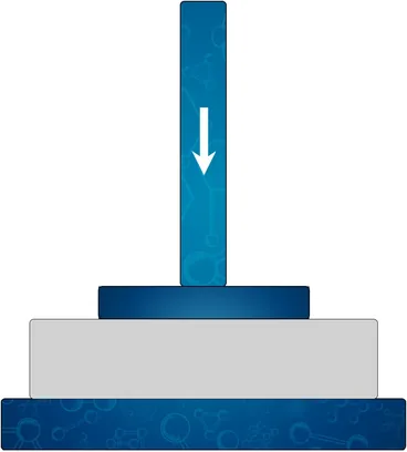
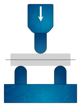







Related technical references
NBR 5739 concrete compression test: fc calculation and the NBR 7222, NBR 12142 and NBR 6136-2 standards
ABNT NBR 5739:2018 (the Brazilian standard for concrete compression testing), reaffirmed in 2023, covers compression testing of cylindrical concrete specimens: continuous loading at 0.45 ± 0.15 MPa/s until failure and fc = 4F/(πD²), in MPa, to three significant figures. See what it requires of the machine and the specimen, the h/d correction, failure types A to G and the related standards: NBR 7222 (splitting tensile test), NBR 12142 (flexural tensile strength) and NBR 12118, withdrawn in February 2026 and replaced by NBR 6136-2:2026.
Flexural test: 3-point and 4-point bending, how to calculate flexural strength, and standards
In a flexural test, a bar supported at two points is loaded until it fails. Learn 3- and 4-point setups, flexural strength and modulus formulas, NBR 12142 and ASTM D790.
ASTM D695: compression testing of rigid plastics (test specimen, 1.3 mm/min and calculations)
ASTM D695-26 measures compressive strength, yield and modulus of rigid plastics: a 12.7 × 12.7 × 25.4 mm prism at 1.3 mm/min. Calculations and ISO 604.
Frequently asked questions
What is a compression test?
It is the mechanical test that applies an increasing axial force to shorten a test specimen and measure strength, yield, modulus and the stress-strain curve. For concrete it follows ABNT NBR 5739:2018 (the Brazilian standard for compression testing of cylindrical concrete specimens), for metals ASTM E9 and for plastics ASTM D695 or ISO 604.
How is a compression test performed?
The test specimen, with flat and parallel faces, is centered between the machine platens, and the force is applied at a controlled rate until fracture or until the strain limit set by the standard, recording force and displacement. For concrete, the loading rate is 0.45 ± 0.15 MPa/s.
How do you calculate compressive strength?
Divide the maximum force by the initial cross-sectional area: σ = F / A0, in MPa. For a concrete cylinder, NBR 5739 uses fc = 4F / (πD²). A 100 mm specimen that fails at 236 kN has 30.0 MPa.
What does NBR 5739 specify?
It defines the test of cylindrical concrete specimens: height/diameter ratio up to 2.06, with a correction below 1.94; machine calibrated to NBR ISO 7500-1 every 12 months; loading at 0.45 ± 0.15 MPa/s until the force drops; result in MPa to 3 significant figures; and 7 fracture types, from A to G. The current edition is the 2018 one.
What is the fck formula?
In mix design, fcm = fck + 1.65·sd, with sd of 4.0, 5.5 or 7.0 MPa depending on preparation condition A, B or C (NBR 12655, the Brazilian standard for concrete preparation, control and acceptance). In the control of lots with 20 or more samples, fck,est = fcm − 1.65·sd. The 1.65 corresponds to a 5% probability of falling below fck.
What does fck 30 MPa mean?
That the concrete was specified so that no more than 5% of the results at 28 days fall below 30 MPa. To ensure this, the mix design targets a higher mean: 36.6 MPa under condition A. A 10 × 20 cylinder at 30 MPa fails at about 236 kN, and a 15 × 30 at about 530 kN.
What is the compressive strength of steel?
Ductile steel does not fracture in compression: it flattens and barrels. That is why the compressive yield strength is used, practically equal to the tensile one, from 250 to 500 MPa for common structural steels.
Why is concrete stronger in compression than in tension?
Because microcracks open into cracks under tension and tend to close under compression. According to NBR 6118 (the Brazilian design standard for concrete structures), the mean tensile strength of a C30 concrete is about 2.9 MPa, close to 10% of its compressive strength.
What is the difference between axial compression and diametral compression?
In axial compression, the cylinder stands upright and the compressive strength is measured (NBR 5739). In diametral compression, or the Brazilian test, the cylinder lies on its side and the load produces tension on the diametral plane: fct,sp = 2F / (π·d·L), according to NBR 7222 (the Brazilian splitting tensile test standard).
Which concrete test specimen should I use, 10 × 20 or 15 × 30?
Both are standard under NBR 5738 (the Brazilian standard for molding and curing concrete specimens), with a height equal to twice the diameter. The 10 × 20 requires about 44% of the force of the 15 × 30 for the same strength and allows smaller presses; the 15 × 30 is used with larger aggregates.
At what age are concrete specimens tested?
The reference age for fck is 28 days, with a tolerance of 24 hours. NBR 5739 also provides for 24 hours, 3, 7, 63 and 91 days, each age with its own tolerance.
What machine is used for the compression test?
A compression testing machine or a universal testing machine with compression platens, a load cell calibrated to ABNT NBR ISO 7500-1 and software. The capacity must be above the expected force: 300 kN corresponds to about 38 MPa on a 10 × 20 cylinder, which covers up to C25 with margin, but with C30 some cylinders exceed this value, and the 600 kN machine is the one recommended; 15 × 30 specimens of high strength classes call for 1,000 kN.