
The coefficient of friction (μ) is the dimensionless number that expresses how much of the normal force is needed to make two surfaces slide over each other: μ = Fat / N. It is a property of the pair of surfaces, not of a single material, and it has two values: the static coefficient (μs), which measures the resistance to starting motion, and the kinetic coefficient (μk), which measures the resistance to keeping it going. Below we go from the physics (formula, inclined plane, table and worked examples) to film testing under ASTM D1894 and ISO 8295.
In short:
- Formula: μ = Fat / N. On a horizontal plane, N = m·g; on an inclined plane, N = m·g·cos θ.
- Quick reading: μ = 0.4 means a tangential force equal to 40% of the normal force is needed to overcome friction.
- Measurement: a sled of known mass is pulled over the material at constant speed; the force peak gives μs and the average during sliding gives μk.
- Film standards: ASTM D1894 (150 mm/min) and ISO 8295 (100 mm/min). Results from the two are not interchangeable.
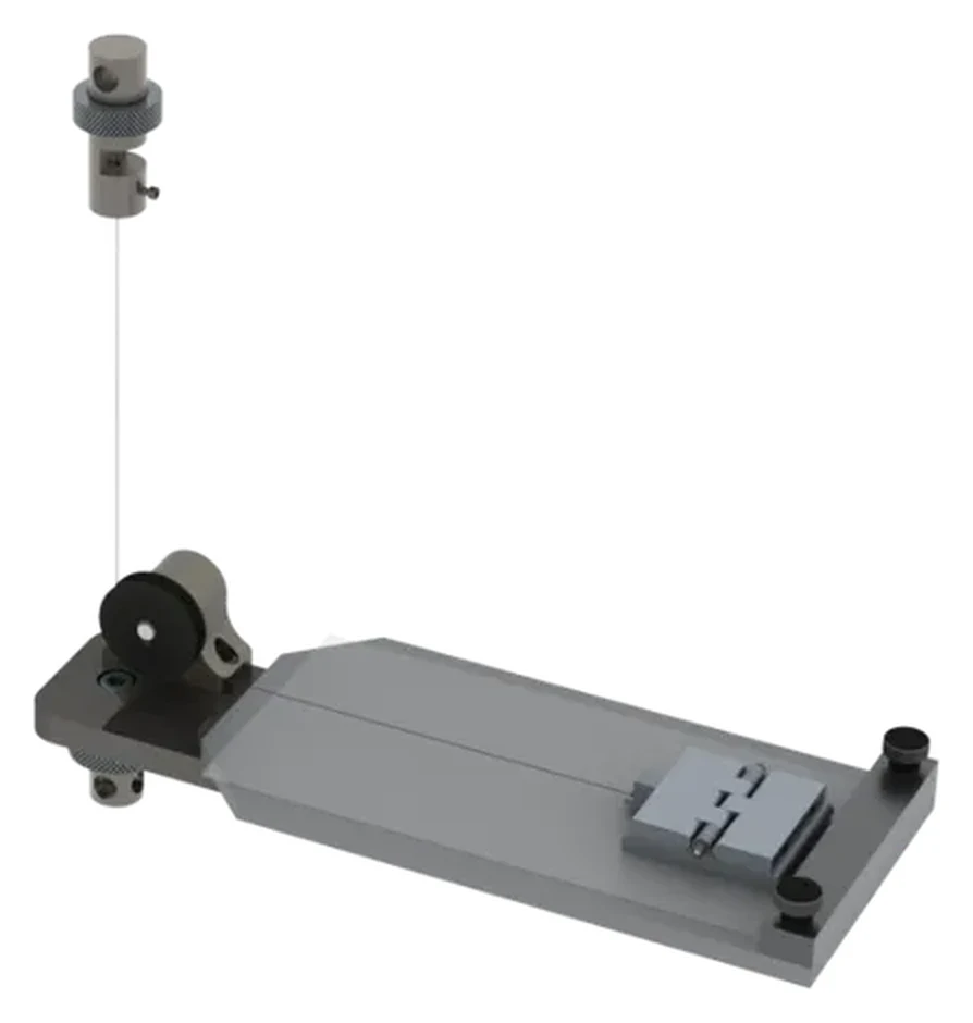
The photo shows the Biopdi coefficient of friction fixture mounted on the universal testing machine. One of the test specimens lies on the horizontal table; the sled, covered with the other, slides over it; and a cable, redirected by the pulley, connects the sled to the load cell, which measures the pulling force as the crosshead moves.
What the coefficient of friction is and its formula
Friction is the force that opposes sliding between two surfaces in contact. It acts tangent to the interface, against the motion or the tendency to move, and arises from the asperities and adhesion between the faces. ISO 20808 defines the coefficient of friction as the dimensionless ratio between the friction force, Ff, and the applied normal force, Fp. ISO 8295, for plastic films, applies the same ratio to both regimes: μs = Fs / Fp for static and μd = Fd / Fp for dynamic, which is the same as kinetic.
Three consequences follow from the definition:
- It is dimensionless. It is the ratio of two forces (N/N), so it has no unit.
- It belongs to the pair, not the material. ASTM D3108 points out that it measures the interaction between two bodies: steel against steel, against PTFE or against rubber gives very different values. The condition of the surfaces (clean, lubricated, wet), the temperature and, for polymers, the speed and contact time also matter.
- It can exceed 1. Clean, identical metals with strong adhesion between the faces exceed 1: dry aluminum on aluminum reaches 1.05 to 1.35 static.
It is one of the surface mechanical properties most used in design and quality control. The table summarizes the formulas used throughout the text:
| Quantity | Formula | Note |
|---|---|---|
| Coefficient of friction | μ = Fat / N | dimensionless |
| Maximum static friction | Fat,e ≤ μs·N | equality only at the onset of sliding |
| Kinetic friction | Fat,c = μk·N | during sliding |
| Normal force on a horizontal plane | N = m·g | g = 9.80665 m/s² (standard value) |
| Normal force on an inclined plane | N = m·g·cos θ | θ is the angle of the plane |
| Inclined plane at the onset of sliding | μs = tan θc | θc: angle at which sliding begins |
| Sled test, static | μs = Fs / (mtrenó·g) | Fs: initial force peak |
| Sled test, kinetic | μk = F̄k / (mtrenó·g) | F̄k: average force during uniform sliding |
Static friction and kinetic friction
While the force applied to a body at rest is small, static friction grows with it and cancels it: if a box pushed with 20 N does not move, friction equals 20 N. This adjustment has a ceiling, μs·N. Beyond it, the body slides and the resistance becomes kinetic friction, μk·N. As TAPPI T 549 puts it, static friction resists the start of motion and kinetic friction resists its continuation.
In general μs is greater than μk: clean, dry steel on steel has μs of 0.5 to 0.8 and μk of 0.42. The rule is not a law: in brake materials, μs at room temperature can be 40 to 50% of the stated average μk (Engineering ToolBox). In a force record, static friction appears as the peak that precedes sliding and kinetic friction as the plateau that follows, as the curve in the test section shows.
Amontons-Coulomb laws and where they fail
Leonardo da Vinci studied friction around 1493, without publishing. Amontons published the laws in 1699, Euler distinguished static from kinetic friction in 1750, and Coulomb consolidated them in 1785 (Popova and Popov, Friction, 2015). The classical statement says that:
- the friction force is proportional to the normal force;
- it does not depend on the apparent contact area;
- kinetic friction is practically independent of sliding speed.
These are approximations that work for rigid solids at moderate pressures. At extreme pressure, friction rises faster than the load and the surfaces can seize; speed independence only holds at low speeds; with a lubricant, friction varies with speed and temperature. Polymers and elastomers depart further from the rule: ISO 8295 warns that films generally do not behave ideally, which is why it fixes all test parameters, and ASTM D1894 notes that the static peak depends strongly on the loading rate and on the contact time before motion.
How to calculate the friction force and the coefficient
The calculation starts from the normal force, which presses one surface against the other: Fat = μ·N or, when measuring the friction force, μ = Fat / N. What changes from one problem to another is how to find N.
On a horizontal plane
For a block resting on a horizontal plane, with no other vertical forces, the normal force equals the weight: N = m·g. A 10 kg block has N = 10 × 9.81 = 98.1 N. With μk = 0.4, the friction force during sliding is Fat = 0.4 × 98.1 = 39.2 N.
This same number answers a frequent question: what does a coefficient of friction of 0.4 mean? It means a tangential force equal to 40% of the normal force is needed to overcome friction. On a horizontal plane, that is 40% of the weight: about 39 N for a 10 kg object. The same μ corresponds to a 21.8° ramp, on which the object would start sliding by itself, because tan 21.8° = 0.4.
On an inclined plane
On an inclined plane, the weight splits into two components: the one parallel to the ramp, m·g·sin θ, tends to make the block slide down; the perpendicular one, m·g·cos θ, is balanced by the normal force, so N = m·g·cos θ (taking N as the full weight is a common mistake). By gradually increasing the angle, you reach the critical angle θc, at which the block starts to slide and the downhill component equals the maximum static friction:
m·g·sin θc = μs·m·g·cos θc, therefore μs = tan θc.
The mass cancels out: the sliding angle depends only on the pair of surfaces. The diagram below brings both cases together. On the left, the block on the horizontal plane, with the weight P, the normal force N, the applied force F and the friction Fat at the interface, opposite to F. On the right, the block on the ramp, with the weight resolved into its two components and friction pointing up the ramp, against the tendency to slide down.
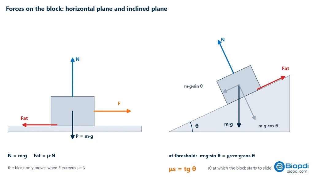
This is the principle of the inclined plane method, which TAPPI T 815 uses to measure the slide angle of packaging materials. The method gives only the static coefficient, because what is read is the angle at which motion begins. ASTM D4918, which applied the same principle to writing and printing paper, was withdrawn in 2010 with no replacement.
Rolling friction is not sliding friction
The rolling resistance of a wheel is a different phenomenon, with a different and much smaller coefficient: for a steel wheel it is on the order of 0.001. It should not be confused with the sliding μ discussed here.
Coefficient of friction table
Coefficient of friction tables compile values from handbooks and serve as an order of magnitude: since μ depends on surface finish, cleanliness, humidity, temperature and method, the same pair varies from one source to another. To specify a material or accept a batch, the value must come from testing the actual pair, according to the product standard.
Some patterns stand out: lubrication lowers the coefficient (steel on steel drops to 0.16 with grease), PTFE has low friction against almost everything, which explains its use in bearings and guides, and ice shows the effect of temperature. The following table comes from the Engineering ToolBox compilation (accessed in 2026); "n/a" indicates a value not available in the source.
| Surface pair | Condition | Static μ | Kinetic μ |
|---|---|---|---|
| Steel × steel | clean and dry | 0.5 to 0.8 | 0.42 |
| Steel × steel | greased | 0.16 | n/a |
| Steel × steel | light mineral oil | 0.23 | n/a |
| Aluminum × mild steel | clean and dry | 0.61 | 0.47 |
| Aluminum × aluminum | clean and dry | 1.05 to 1.35 | 0.4 |
| Brass × steel | clean and dry | 0.51 | 0.44 |
| Copper × steel | clean and dry | 0.53 | 0.36 |
| Rubber × asphalt | dry | 0.9 | 0.5 to 0.8 |
| Rubber × asphalt | wet | n/a | 0.25 to 0.75 |
| Rubber × concrete | dry / wet | n/a | 0.6 to 0.85 / 0.45 to 0.75 |
| Wood × wood | clean and dry | 0.25 to 0.5 | n/a |
| Oak × oak | dry, parallel to the grain | 0.62 | 0.48 |
| PTFE × steel | clean and dry | 0.05 to 0.2 | n/a |
| PTFE × PTFE | clean and dry | 0.04 | 0.04 |
| Polyethylene × steel | clean and dry | 0.2 | n/a |
| Nylon × steel | clean and dry | 0.4 | n/a |
| Glass × glass | clean and dry | 0.9 to 1.0 | 0.4 |
| Ice × ice | 0 °C | 0.1 | 0.02 |
| Ice × ice | −12 °C | 0.3 | 0.035 |
| Ice × steel | clean | 0.03 | n/a |
The method also changes the number: in the ASTM G99-23 interlaboratory study (ball-on-disk, 28 laboratories), steel on steel gave μ of 0.60 ± 0.11, above the 0.42 in the table, because the geometry and contact regime are different.
Worked examples
The three examples below apply the physics formulas, with g = 9.81 m/s². The calculations for the laboratory test appear after the test is presented.
Example 1: block on a horizontal plane
A 10 kg box rests on the floor, with μs = 0.5 and μk = 0.4. (a) What is the minimum force to start motion? (b) And to keep it moving at constant speed? (c) With a 45 N push, what is the friction force?
- Normal force: N = 10 × 9.81 = 98.1 N.
- (a) Fat,e,máx = 0.5 × 98.1 = 49.05 N.
- (b) Fat,c = 0.4 × 98.1 = 39.24 N.
- (c) Since 45 N is less than 49.05 N, the box does not move, and static friction equals 45 N: it adjusts to the applied force up to the limit.
Example 2: inclined plane
A block starts to slide when the ramp reaches 22°. What is the μs of the pair?
- μs = tan 22° = 0.404.
- Conversely, a pair with μs = 0.4 starts to slide at θ = arctan 0.4 = 21.8°.
Example 3: what μ = 0.4 means for a pallet
A pallet with a total mass of 25 kg sits on a floor with μs = 0.4. What horizontal force starts it sliding?
- N = 25 × 9.81 = 245.25 N.
- F = 0.4 × 245.25 = 98.1 N, that is, 40% of the weight.
Coefficient of friction test for films: ASTM D1894 and ISO 8295
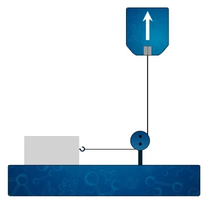
In the laboratory, the friction of plastic film and sheeting is measured on a horizontal plane. ASTM D1894 determines the static and kinetic coefficients of film and sheeting sliding over itself or over another material; ISO 8295 does the same for non-blocking films up to about 0.5 mm thick. It is a quality control test: ISO 8295 warns that it does not fully evaluate how the film behaves on a packaging machine. Both standards allow a tensile testing machine, with the crosshead motion redirected to the horizontal by a pulley, as in the fixture in the photo at the top. It is one of the mechanical tests performed on a universal testing machine with a dedicated accessory.
Test procedure, step by step
- Condition the samples in the atmosphere specified by the standard: per ASTM D618 for D1894; for at least 16 h at 23 °C and 50% relative humidity (ISO 291) for ISO 8295.
- Cut the test specimens without touching the face to be tested. In D1894, the sled film is about 120 mm long; in ISO 8295, the pairs are 80 × 200 mm, in the machine direction.
- Fix one specimen to the horizontal table and wrap the sled with the other, noting which faces are in contact.
- Connect the sled to the load cell with the cord running over the pulley, keeping the cord horizontal and aligned with the direction of motion.
- Pull the sled at constant speed: 150 ± 30 mm/min in D1894; 100 ± 10 mm/min in ISO 8295.
- Record the force with data acquisition fast enough to capture the initial peak.
- Calculate μs from the peak and μk from the average of the uniform sliding portion, and repeat on the remaining specimens (5 in D1894; at least 3 pairs in ISO 8295).
D1894 also allows the reverse arrangement, with the sled stationary and the plane moving, which gives the same results, and provides for a heated or cooled plane as an option.
How to read the force vs. displacement curve
As in the stress-strain curve of a tensile test, each portion of the curve corresponds to a regime. In the sled test there are three:
- Ramp: the force rises while the cord (or the spring, in ISO 8295) stretches; the sled has not moved yet.
- Initial peak: this is the static friction force Fs. ISO 8295 states explicitly that the first force peak is caused by static friction.
- Plateau: after the peak, the force drops and oscillates around a steady value; this is the kinetic regime. D1894 averages over at least 130 mm of sliding, discarding the peak.
The graph below shows these portions in a D1894 test with a 200 g sled. In the upper trace, in orange, the 0.78 N peak and the plateau averaging 0.55 N within the 130 mm blue window. In the lower trace, the same test on a pair that shows stick-slip.
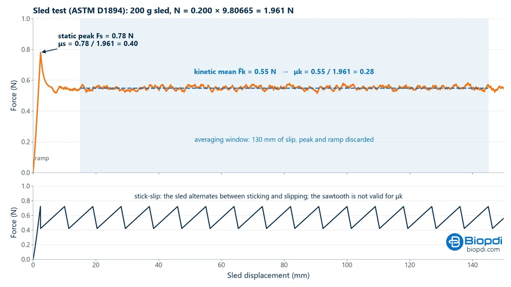
Stick-slip is the regular sawtooth pattern produced when the sled alternates between sticking (force rises) and slipping (force drops suddenly). ISO 8295 does not accept this portion for the dynamic coefficient and requires repeating the test with a rigid connection instead of the spring; the rigid measurement, in turn, is not valid for the static coefficient because of the inertia error. The peak also grows with the time the faces remain at rest in contact, which is why ISO 8295 sets a 15 s rest before pulling.
Worked example: calculation per ASTM D1894
A PE film is tested against itself with the 200 g sled at 150 mm/min. The software records an initial peak of 0.78 N and an average of 0.55 N over the uniform sliding portion (130 mm, peak discarded), which are the values in the graph above.
- Normal force: N = 0.200 kg × 9.80665 m/s² = 1.961 N.
- μs = 0.78 / 1.961 = 0.40.
- μk = 0.55 / 1.961 = 0.28.
Since the sled mass is fixed, every 0.1 N of force corresponds to about 0.05 of coefficient. How to interpret this result for packaging is covered in the section on films, just ahead.
ASTM D1894 or ISO 8295
Both standards use the same principle, a sled of about 200 g pulled over the film, but they change parameters that affect the result: speed, sled-to-load-cell connection, rest time, averaging portion and conditioning. The comparison below shows where they differ:
| Parameter | ASTM D1894-24 | ISO 8295:1995 |
|---|---|---|
| Sled | 200 g, 63.5 mm face | 200 ± 2 g (1.96 N), 40 cm² base (63 mm) with felt |
| Speed | 150 ± 30 mm/min | 100 ± 10 mm/min (500 mm/min for special films, to be reported) |
| Static measurement | initial force peak | initial peak, with a 2 ± 1 N/cm spring and 15 s rest |
| Kinetic average | at least 130 mm, excluding the peak | portion following the peak, about 6 cm |
| Test specimens | 5 | at least 3 pairs of 80 × 200 mm |
| Conditioning | ASTM D618 | at least 16 h at 23 °C and 50% RH (ISO 291) |
That is why the results are not interchangeable: a film with μk = 0.28 under one standard will not necessarily give 0.28 under the other. The test report and the purchase specification must state the standard.
Coefficient of friction in packaging
In flexible packaging, the coefficient of friction determines how the film runs through filling machines and how bags stack: too much friction makes the film stick on forming collars and guides; too little makes the stack slide off the pallet. According to ISO 8295, the COF of films ranges from about 0.2 to 1, and the industry classifies it as low (up to 0.20), medium (0.20 to 0.40) and high (above 0.40), according to Mazo (Plastics Engineering, 2025). A COF of 0.4 to 0.7 is high: typical of film without slip additive or of an anti-slip face, which for stacking targets μs above 0.45.
On vertical form-fill-seal (VFFS) machines, the reference is a COF of 0.200 to 0.300 on the inner face and 0.300 to 0.400 on the outer face, with the outside about 0.100 higher (Viking Masek, 2020). The static coefficient matters for stacked bags; the kinetic one, for the roll running over the metal parts. Since the faces may differ (treated or untreated, inner or outer), ISO 8295 requires identifying them and testing the combination of interest: 1 against 1, 2 against 2 or 1 against 2. The PE film in the worked example, with μk = 0.28, has a medium COF, within the VFFS inner-face range; the value for each line, however, should be agreed with the machine manufacturer.
The COF of polyolefins is controlled by amide slip additives, such as erucamide and oleamide, which migrate to the surface after extrusion: with 200 to 2000 ppm in the film, the COF falls between 0.1 and 0.4 (Plastics Technology, 2006). Since migration depends on time and temperature, the age of the film changes the result. Lamination can undo the effect: in the same source, films with erucamide jumped from about 0.2 to 0.68 to 0.85 after being laminated to PET with a polyurethane adhesive. The table summarizes these references:
| Reference | Value | Source |
|---|---|---|
| Typical COF range of films | 0.2 to 1 | ISO 8295:1995 |
| Low / medium / high | up to 0.20 / 0.20 to 0.40 / above 0.40 | Mazo, Plastics Engineering, 2025 |
| Anti-slip for stacking | μs above 0.45 | Mazo, 2025 |
| VFFS: inner / outer face | 0.200 to 0.300 / 0.300 to 0.400 | Viking Masek, 2020 |
| Amide additives | COF 0.1 to 0.4, with 200 to 2000 ppm | Plastics Technology, 2006 |
| Non-migratory slip additive | COF 0.20 to 0.40 | Plastics Technology, 2006 |
| Erucamide after lamination to PET | from about 0.2 to 0.68 to 0.85 | Plastics Technology, 2006 |
COF is rarely the only test run on a film. The same universal testing machine performs the tensile test of films (strength and elongation per ASTM D882) and the peel test of tapes and laminates, which measures adhesion between layers.
Coefficient of friction standards by material
Beyond films, each family of materials has its own method, and the setup changes with it. Since the value depends on the method, the standard is part of the result.
- Paper and board: ISO 15359 and TAPPI T 549 use the horizontal plane, like films; ISO 15359 measures the static coefficient before, and the static and kinetic coefficients after, a specified wear. TAPPI T 815 measures the slide angle on an inclined plane. This matters for feeding printers and converting machines.
- Ceramic floor tiles: ABNT NBR 16919:2020 (a Brazilian standard) determines the dynamic coefficient of friction of ceramic floor tiles, related to slip safety. For floors and pavements the British pendulum, described in ASTM E303, is also used; it measures slip resistance by a different principle.
- Textiles: ASTM D3108 measures the friction of yarn against a solid surface, such as guides and needles; D3412, of yarn against yarn.
- Tribology: ASTM G99 and ISO 20808 (advanced ceramics) measure friction and wear with a pin or ball on a rotating disk. ASTM G115 guides the choice of method and the minimum content of the report.
The table lists the standards cited, with the current edition:
| Standard | Material | Method |
|---|---|---|
| ASTM D1894-24 | plastic film and sheeting | sled on horizontal plane, static and kinetic |
| ISO 8295:1995 | plastic film and sheeting | sled on horizontal plane, static and kinetic |
| ISO 15359:1999 | paper and board | horizontal plane, static and kinetic |
| TAPPI T 549 om-25 | writing and printing paper | horizontal plane, static and kinetic |
| TAPPI T 815 om-24 | packaging materials | inclined plane (slide angle), static |
| ABNT NBR 16919:2020 | ceramic floor tiles | dynamic coefficient of friction |
| ASTM D3108/D3108M-13(2020) | yarn against solid | kinetic friction of running yarn |
| ASTM D3412/D3412M-13(2020) | yarn against yarn | yarn-to-yarn friction |
| ASTM G99-23 | materials in general | pin or ball on disk, friction and wear |
| ISO 20808:2016 | advanced ceramics | ball on disk, dry |
| ASTM G115-24 | solids in general | guide for measuring and reporting friction coefficients |
Common errors in the coefficient of friction test
With forces ranging from tenths of a newton to a few newtons, setup and handling details weigh on the result. The most frequent errors:
- Load cell too large for forces of a few newtons (see the calculation in the example in the machine section).
- Cord not horizontal or misaligned: a force component enters the reading (ISO 8295).
- Table or sled out of level. The normal force is no longer equal to the sled weight.
- Touching the test face: grease, dust and creases change the friction.
- Mixing standards: 150 mm/min is D1894; 100 mm/min is ISO 8295.
- Slow data acquisition: flattens the peak and underestimates μs; ISO 8295 requires a response time of 0.5 s or less.
- Not discarding the ramp and the peak when calculating μk.
- Uncontrolled rest time: inflates the peak; ISO 8295 sets 15 s.
- Using the sawtooth stick-slip portion for μk.
- Not identifying the faces and the combination (1/1, 2/2, 1/2; film against film or film against metal).
- Ignoring the age of the film and the migration of slip additive.
- Short conditioning, below the 16 h of ISO 8295 or what ASTM D618 specifies.
- Forgetting the inertia error: in ISO 8295 it raises μ by about 0.005, or 2.5% of a μ of 0.2.
How to run the test on the Biopdi universal testing machine
At Biopdi, the coefficient of friction test is run on the universal testing machine (UTM) with the coefficient of friction fixture per ASTM D1894. The horizontal table with the sled and the pulley replaces the grips, the crosshead pulls the sled at constant speed and the load cell measures the force. The panel below shows the machine, what each part does in the friction test and the fixture used.
The universal testing machine in the coefficient of friction test
The M2 line includes single-column models from 200 N to 10 kN and dual-column models from 5 kN to 1,000 kN. Each part of the machine has a job in the test:
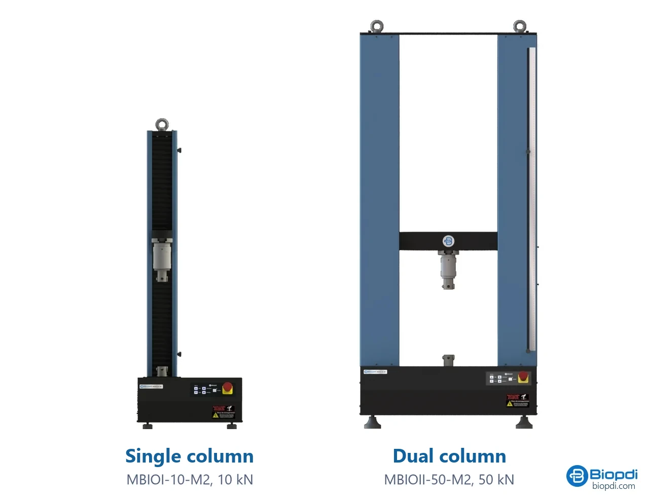
- Moving crosshead pulls the sled at constant speed
- Load cell small, for forces of a few newtons
- Friction fixture horizontal table, sled and pulley
- Sled 200 g and 63.5 mm in ASTM D1894
- BioLab software static peak, kinetic average and report
- Control panel and emergency stop positions and stops the test
Fixtures for the coefficient of friction test
The fixture below mounts on the same machine, in place of the grips:
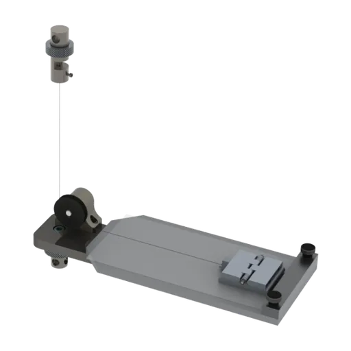
For films, tapes and paper, the recommended model is the MBIOI-1P-M2 portable universal testing machine, from 200 N to 1 kN, with load cells from 50 N to 1 kN. Its speed range covers the 150 mm/min of D1894 and the 100 mm/min of ISO 8295, and the BioLab software calculates the static peak and the kinetic average over the window set by the operator, with a report and curve export. The report should state the standard, the faces in contact, the sled mass, the speed, the conditioning and the age of the film.
Worked example: choosing the load cell
In the example test, the forces stay below 1 N (peak of 0.78 N). Compare a 1 kN load cell with a 50 N one.
- 0.78 N is 0.078% of 1 kN and 1.56% of 50 N.
- With the 1 kN load cell, the measured force falls far below the low end of the working range. The accuracy class from verification per NM ISO 7500-1 (the Mercosur/Brazilian adoption of ISO 7500-1) only applies within the verified range of the load cell, so the measurement loses reliability.
- Answer: use the smallest load cell that covers the maximum force with margin, here the 50 N one, with fast data acquisition to capture the static peak.
The same machine runs tensile tests on films and tapes and peel tests on adhesives, changing only the fixture. To configure the machine for your material, request a quote.
Other tests and technical references
Tests performed on the Biopdi universal testing machine









Related technical references
Fracture toughness testing (KIc): test, formula, standards and values
Fracture toughness (KIc) is the resistance to crack propagation. See the formula, the ASTM E399 test with a clip gauge, J, CTOD and typical values.
Vickers hardness test and microhardness: HV formula, force ranges, case depth profile and conversion to HRC
Vickers and microhardness testing: HV = 0.1891·F/d², ISO 6507-1:2023 force ranges, case depth profile at 550 HV, HRC conversion and what hardness can't tell you.
Tear test: tear strength testing, standards and calculation
The tear test measures the force to start or grow a tear in rubber, film, fabric and leather. ASTM D624, ISO 34-1, D1938, D2261 standards and calculation.
Frequently asked questions
What is the formula for the coefficient of friction?
μ = Ff / N: the friction force divided by the normal force. Since it is the ratio of two forces, it has no unit. In film testing, the static coefficient is the peak force divided by the sled weight (m·g) and the kinetic coefficient is the average force during sliding divided by the same weight, as defined in ASTM D1894 and ISO 8295.
What does a coefficient of friction of 0.4 mean?
It means a tangential force equal to 40% of the normal force is needed to overcome friction. A 10 kg object on the floor needs about 39 N. The same value corresponds to a 21.8° ramp, where the object starts to slide, because tan 21.8° = 0.4.
What does a COF of 0.4 to 0.7 mean for plastic film?
It is a high COF, above 0.40 in the classification used by the film industry (Plastics Engineering, 2025). It is typical of film without slip additive or with an anti-slip outer face, and it can make the film stick in packaging machines.
How do you calculate the friction force (Ff)?
Ff = μ·N. On a horizontal plane, N = m·g; on an inclined plane, N = m·g·cos θ. Example: a 10 kg block with μk = 0.4 on a horizontal plane has Ff = 0.4 × 98.1 = 39.2 N during sliding.
What is the difference between static and kinetic friction?
Static friction prevents motion from starting and grows with the applied force up to the maximum μs·N; kinetic (or dynamic) friction acts during sliding and equals μk·N. In general μs is greater than μk (dry steel on steel: 0.5 to 0.8 versus 0.42), but there are exceptions, such as brake materials.
Can the coefficient of friction be greater than 1?
Yes. Clean, identical metals exceed 1 because of adhesion between the faces: dry aluminum on aluminum has a static coefficient of 1.05 to 1.35. There is no theoretical limit at 1.
How do you measure the coefficient of friction in the lab?
A sled of known mass is pulled over the test specimen at constant speed and the force is recorded, on a universal testing machine with a friction fixture. For plastic films, the standards are ASTM D1894 (150 mm/min) and ISO 8295 (100 mm/min). There are also the inclined plane method (TAPPI T 815) and the pin-on-disk method (ASTM G99).
What is the difference between ASTM D1894 and ISO 8295?
Both use a sled of about 200 g on a horizontal plane, but D1894 pulls at 150 ± 30 mm/min and averages the kinetic force over at least 130 mm, while ISO 8295 pulls at 100 ± 10 mm/min, uses a spring for the static measurement and sets a 15 s rest time. The results are not interchangeable: the report must state the standard.
How do you find the coefficient of friction on an inclined plane?
The plane is tilted until the block starts to slide, and μs = tan θ is calculated. TAPPI T 815 uses this principle for packaging materials. The method gives only the static coefficient.
What is stick-slip in a friction test?
It is the regular sawtooth pattern in the force curve, with the sled alternating between sticking and slipping. ISO 8295 does not accept the oscillating section for the dynamic coefficient and requires the measurement to be repeated with a rigid connection in place of the spring.
What COF does a film need for a packaging machine?
For VFFS machines, the market reference is 0.200 to 0.300 on the inner face and 0.300 to 0.400 on the outer face, with the outside higher (Viking Masek, 2020). The right value depends on the machine and should be agreed with the equipment manufacturer.
Is there a Brazilian standard for the coefficient of friction?
Yes. ABNT NBR 16919:2020 (Ceramic tiles: determination of the coefficient of friction) is the Brazilian standard that measures the dynamic coefficient of friction of ceramic floor tiles. For plastic films, ASTM D1894 or ISO 8295 is used.