
The impact test is a dynamic test in which a pendulum breaks a notched test specimen with a single blow. The energy absorbed in the fracture, in joules (KV), measures notch toughness and shows whether the material behaves in a ductile or brittle manner at that temperature. There are two pendulum methods. In the Charpy test the specimen is supported at both ends (ISO 148-1:2016, ABNT NBR ISO 148-1:2021 in Brazil, and ASTM E23). In the Izod test the specimen is clamped as a cantilever, and the method is used mostly for plastics (ASTM D256 and ISO 180). When the Charpy test is repeated at several temperatures, it reveals the ductile-to-brittle transition temperature of steels.
The impact test exists because a steel that elongates a lot in a slow tensile test can shatter like glass under a sudden blow in the cold. This guide covers how the pendulum works, the difference between Charpy and Izod, the test specimen, what is measured besides energy, the step-by-step procedure, the transition curve, acceptance criteria, worked examples, drop-weight tests, impact testing of each class of material and the standards. It also includes a calculator.
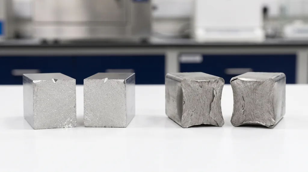
The photo shows two steel Charpy specimens after the blow. The one on the left failed in a brittle manner: the surface is flat and shiny, and the edges barely deformed. The one on the right failed in a ductile manner: the surface is fibrous and dull, and the edges spread out. The test turns this difference into a number, the absorbed energy.
What is the impact test
ISO 148-1 describes the Charpy test as the method for determining the energy absorbed in an impact test of metallic materials. The notched specimen, supported at both ends, is broken by a single pendulum blow on the side opposite the notch. Besides the energy, lateral expansion and fracture appearance are often determined as well, and both are explained later in this article. ASTM E23 notes that, for some materials and temperatures, the result, when correlated with service experience, is a good predictor of the likelihood of brittle fracture.
The test measures notch toughness at a high strain rate. That is the ability of the material to absorb energy when a notch concentrates the stress and the load arrives all at once, within milliseconds. It does not measure static strength, does not give a direct design value and does not provide the fracture toughness KIC, which requires a specimen with a real crack and a fracture mechanics test. It is a comparative and acceptance test. Static toughness, the area under the tensile test curve, is a different measure, and the two complement each other.
In industry, the impact test is used to accept lots of steel plates, sections, pipes and forgings against an energy requirement at a given temperature, as in structures, pressure vessels and piping. It is also used to qualify welding procedures, by testing the weld metal and the heat-affected zone, and to select materials for low-temperature service. In plastics and composites development, it is used to compare formulations for resistance to impact.
A bit of history: S. B. Russell used a pendulum to measure the work of fracture in 1898, and Georges Charpy standardized the notched specimen and the method in 1901, with a machine very similar to today's in 1905. ASTM published the first E23 in 1933.
How the pendulum works and how the energy is calculated
The impact testing machine is a pendulum: an arm that rotates on an axis, with a hammer at the end. The edge of the hammer that strikes the specimen is the striker, with a radius of 2 mm or 8 mm. The supports, where the specimen is placed, sit at the base (in the Izod test, a vise is used instead). A release mechanism holds the hammer at the starting angle and lets it go without adding any push. A dial with a drag pointer, or an encoder on the axis, records how high the pendulum rose after the blow. A guard around the strike area keeps the operator out of reach of the hammer and of flying fragments.
The principle is conservation of energy. The hammer is raised to an angle α, measured from the vertical, and released. It breaks the specimen at the lowest point and keeps rising to an angle β. If nothing had been broken, it would rise again to nearly α. The energy missing to get there is the energy the specimen absorbed in the fracture.
In the simplified model used for the calculations in this article, the mass m of the pendulum is concentrated at a distance R from the axis. The product m·g·R is the pendulum moment, M. Falling from α to the lowest point, the hammer drops a height h0 = R·(1 − cos α), and the energy available at impact is Kp = M·(1 − cos α). After the fracture, the remaining energy is what carries the hammer up to β, M·(1 − cos β). The difference between the two is the absorbed energy, K = M·(cos β − cos α). The impact velocity comes from the same drop: v = √(2·g·h0). In a real pendulum the mass is distributed, and the moment M is determined directly when the machine is verified.
The table summarizes the formulas:
| Quantity | Formula | Note |
|---|---|---|
| Pendulum moment | M = m·g·R | simplified model: mass concentrated at R from the axis |
| Available energy | Kp = M·(1 − cos α) | α measured from the vertical |
| Absorbed energy | K = M·(cos β − cos α) | no friction; K = m·g·(h0 − h1) |
| Impact velocity | v = √(2·g·h0) | h0 = R·(1 − cos α) |
On a real machine, friction at the axis and air resistance also consume energy, and that loss would be read as if the specimen had absorbed it. This is why ISO 148-1 requires friction losses to be checked every day and limits their total to 0.5% of the nominal energy. The pendulum capacity must also match the material: under ASTM E23, a reading above 80% of the available energy is inaccurate and must be reported as approximate, and in that case a larger pendulum is used. In metals laboratories, 300 J is the typical capacity. The calculator below does the pendulum calculations and checks the acceptance of a set of three specimens, using the rule explained later in "Acceptance criteria".
Interactive simulation
Try the test in your browser and watch the results being calculated.
Difference between the Charpy and Izod impact tests
Both tests use the same pendulum. What changes is how the specimen is held and which side is struck. In the Charpy test, the specimen lies on two supports, like a simply supported beam, and the striker hits it in the middle, on the side opposite the notch: the notch is on the side placed in tension by bending. In the Izod test, the specimen stands upright, clamped in a vise up to the notch, like a cantilever beam, and the hammer strikes it above the vise, on the notch side. The diagram below compares the two setups.
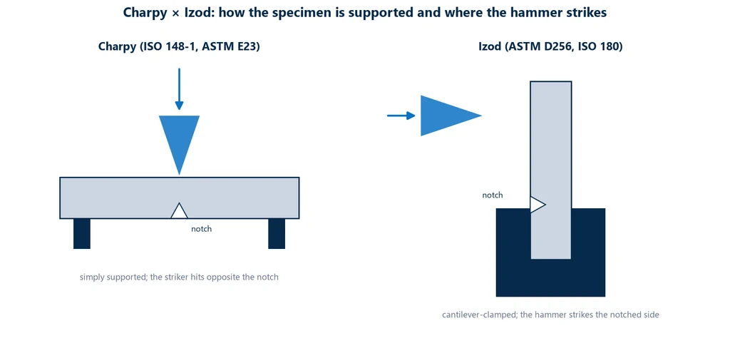
In practice, Charpy dominates for metals and Izod is more common for plastics. The result is also expressed differently: for metals, energy in joules; for plastics, energy divided by the specimen width (J/m, in ASTM D256) or by the area under the notch (kJ/m², in ISO 179-1 and ISO 180). For tests below room temperature, Charpy has the advantage: the specimen just has to be taken out of the bath and placed on the supports within a few seconds, while Izod requires clamping it in the vise. The table summarizes the differences:
| Aspect | Charpy | Izod |
|---|---|---|
| Fixture | simply supported, horizontal | clamped as a cantilever, vertical |
| Blow | on the side opposite the notch | on the notch side, above the vise |
| Main use | metals (ISO 148-1, ASTM E23); plastics (ISO 179-1) | plastics (ISO 180, ASTM D256); rare for metals |
| Result | KV or KU in J (metals); kJ/m² (ISO 179-1) | J/m (ASTM D256); kJ/m² (ISO 180) |
| Low-temperature testing | easy: the specimen just has to be positioned in less than 5 s | harder, because it has to be clamped in the vise |
Charpy and Izod results cannot be converted into each other. It is also an oversimplification to say that "Charpy is for metals and Izod is for plastics": there is a Charpy test for plastics (ISO 179-1), and ASTM E23 covers Izod testing of metals.
Charpy test specimen and notch
The notch is what makes the test severe and reproducible. It concentrates the stress at a known point, creates a stress state at the root that restrains plastic deformation and forces the fracture to start there. Because the result depends heavily on this geometry, the standard fixes the dimensions of the specimen and the notch. In ISO 148-1:
- Standard specimen: 55 mm long with a 10 × 10 mm square cross section.
- V-notch: 45°, 2 mm deep, with a 0.25 mm root radius, leaving an 8 mm ligament, which is the section of material below the notch, the part that actually breaks.
- U-notch: 5 mm deep with a 1 mm radius.
- Subsize specimens: 7.5, 5 or 2.5 mm thick, when the material does not allow the standard size. ISO 148-1 warns that comparisons only make sense between specimens of the same shape and size.
- Preparation: machine and notch after the final heat treatment, with the notch root free of machining marks. The notch plane must lie within 0.5 mm of the midpoint between the supports.
For plastics, the ISO 179-1 and ISO 180 specimens are smaller bars. In the type used in example 5, the thickness is 4 mm and 8 mm of width remain below the notch.
The striker radius, 2 mm or 8 mm, also changes the result, and the two can give different energies for the same material. This is why the result notation includes the notch type and the striker radius: KV2, KV8, KU2 and KU8, where V or U is the notch and 2 or 8 is the radius in mm. ISO 148-1 requires stating which striker was used; ASTM E23 uses the 8 mm striker as standard. In Europe, the 2 mm striker is the most common.
Results beyond absorbed energy
Energy is not the only result. The fracture surface and the deformation of the specimen show how it broke, and a few measurements complement the figure in joules:
- Fracture appearance (%): the percentage of the area that failed by shear, estimated by visual comparison or measurement. The part that failed by shear, in a ductile manner, is fibrous and dull. The part that failed by cleavage, the brittle fracture that splits the grains along crystal planes, is flat, shiny and crystalline. These are the two surfaces in the photo at the beginning of the article.
- Lateral expansion (mm): the maximum increase in specimen thickness on the compression side, measured on both halves (ASTM E23). The more the material deforms before breaking, the greater the expansion, so it indicates ductility and serves as a criterion for the transition temperature.
- Instrumented test (ISO 14556:2023): a force sensor in the striker records the force × displacement curve during the blow and separates the initiation energy from the propagation energy. The standard warns that the result is not to be used directly in safety calculations.
- Old unit in J/cm²: energy divided by the area below the notch (0.8 cm² for the standard V-notch). ISO 148-1 reports in joules, and J/cm² does not convert between notch geometries.
The Charpy test does not provide KIC: the notch is blunt (0.25 mm, not a crack), the loading rate is much higher and the specimen is small. Empirical correlations exist, such as Barsom and Rolfe's (1970), but validation studies show errors of 6% to 18%: they serve as estimates, never as design values.
How to perform the Charpy test, step by step
- Machine and notch the specimens after heat treatment, in the specified orientation (longitudinal or transverse to the rolling direction).
- Condition them at the test temperature: ±2 °C in ISO 148-1 and ±1 °C in the bath in ASTM E23. At room temperature, 23 ± 5 °C (ISO) or 20 ± 5 °C (ASTM).
- Check the friction of the pendulum before the first test of the day.
- Position the specimen on the supports, centered, within 5 seconds of taking it out of the bath. If it takes longer, it goes back into the bath.
- Release the pendulum and read the absorbed energy.
- Measure lateral expansion and fracture appearance, when required.
- Report the energy with the notch and striker type (KV2 or KV8), the temperature, the orientation and the specimen size. A specimen that did not break is reported as "unbroken".
Ductile-to-brittle transition temperature
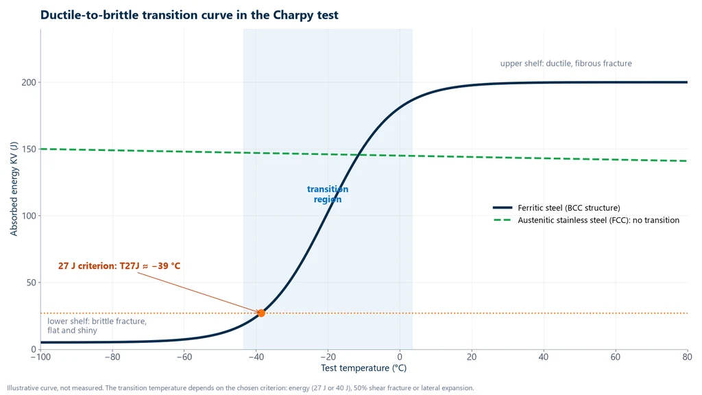
When specimens of the same ferritic steel are tested at several temperatures, the absorbed energy traces an S-shaped curve: high in the warm range, low in the cold, with a transition region between the two. The graph below shows this curve, the 27 J criterion applied to it and, for comparison, the nearly flat curve of an austenitic stainless steel.
Each part of the curve corresponds to a type of fracture:
- Upper shelf: high energy, shear fracture, fibrous and dull, with large lateral expansion.
- Transition region: a mix of cleavage and shear, with wide scatter between specimens.
- Lower shelf: low energy, cleavage fracture, shiny and crystalline, with no lateral expansion.
The transition temperature is not a single number: it depends on the criterion. ISO 148-1 uses Tt27 (27 J energy), Tt50%US (50% of the upper shelf), Tt50%SFA (50% shear fracture, also called FATT) and Tt0.9 (0.9 mm lateral expansion). The same steel can have transition temperatures 25 °C apart depending on the criterion, as example 4 shows later on.
Why does ferritic steel have a transition while austenitic stainless steel does not? Metals with a body-centered cubic (BCC) structure, such as ferritic steel, have a yield stress that rises sharply in the cold, and they start to fail by cleavage. Metals with a face-centered cubic (FCC) structure, such as austenitic stainless steel, aluminum, copper and nickel, do not undergo this change: the energy drops only slightly with temperature, which is why they are used in cryogenic service. Carbon content also matters: in a study of steels with 0.11% to 0.80% carbon, the midpoint of the transition rose from −46 °C to 131 °C.
Two historical cases show what is at stake. The hull steel of the Titanic had a transition temperature (27 J) of +40 °C in the longitudinal direction and +70 °C in the transverse direction, and the water at the time of the collision was at −2 °C (Foecke, NIST, 1998); a modern A36 structural steel is around −15 °C. In the World War II Liberty ships, mass-produced with welded hulls, only 8 of the 83 samples from 48 ships analyzed by the National Bureau of Standards had a transition below 7 °C.
Acceptance criteria: JR, J0, J2 and K2
When steel is purchased, the impact test shows up as a requirement of the product specification: a minimum energy at a defined temperature. For the structural steels of EN 10025-2, this requirement is part of the steel name itself, as a subgrade suffix. An S355J2, for example, is a structural steel with a minimum yield strength of 355 MPa (up to 16 mm) and at least 27 J at −20 °C in the Charpy V-notch test. The table shows the four subgrades:
| Subgrade (EN 10025-2) | Minimum energy KV | Temperature |
|---|---|---|
| JR | 27 J | +20 °C |
| J0 | 27 J | 0 °C |
| J2 | 27 J | −20 °C |
| K2 | 40 J | −20 °C |
Because the energy varies from one test specimen to another, especially near the transition, acceptance is based on a set of specimens. Typically 3 specimens are tested per condition. Under the EN 10025 rule, the lot is accepted if the average of the 3 reaches the minimum, no more than one value falls below it and none falls below 70% of the minimum. If not, 3 more are tested, and the average of the 6 must reach the minimum, with no more than 2 values below it and no more than 1 below 70%. ASTM A673 uses a different criterion.
Impact test solved examples
Example 1: energy from the pendulum angles. A pendulum with m = 20.0 kg and R = 0.800 m is released from α = 150° and rises to β = 60° after breaking the test specimen. Neglect friction.
M = 20.0 × 9.81 × 0.800 = 156.96 N·m. Kp = 156.96 × (1 − cos 150°) = 292.9 J. K = 156.96 × (cos 60° − cos 150°) = 156.96 × 1.366 = 214.4 J, which is 73% of the available energy, below 80%: valid reading. Impact velocity: h0 = 0.800 × 1.866 = 1.493 m, v = √(2 × 9.81 × 1.493) = 5.41 m/s.
Example 2: the old J/cm² unit. A standard V-notch specimen absorbed 64 J. The area below the notch is 10 × 8 mm = 0.80 cm², so 64 / 0.80 = 80 J/cm². With a U-notch (5 mm ligament, 0.50 cm²), the same energy would give 128 J/cm². That is why ISO 148-1 reports in joules.
Example 3: acceptance of an S355J2 (27 J at −20 °C).
Lot A: 35, 24 and 30 J. Average of 29.7 J ≥ 27 J; one value below 27 J (24 J), but above 0.70 × 27 = 18.9 J. Accepted. Lot B: 32, 17 and 34 J. Average of 27.7 J ≥ 27 J, but 17 J is below 18.9 J. Retest with 3 more test specimens.
Example 4: reading the transition curve. Hypothetical KV2 data: −60 °C: 8 J; −40 °C: 15 J; −20 °C: 45 J; 0 °C: 120 J; +20 °C: 180 J; +40 °C: 190 J (upper shelf of about 190 J).
Tt27, interpolating between −40 and −20 °C: −40 + 20 × (27 − 15)/(45 − 15) = −32 °C. Tt50%US: 0.5 × 190 = 95 J, between −20 °C and 0 °C: −20 + 20 × (95 − 45)/75 = −6.7 °C. The same steel has "transition temperatures" 25 °C apart depending on the criterion. With 45 J at −20 °C, it meets J2 and also K2 (40 J).
Example 5: Izod on plastic. Under ASTM D256, 0.30 J on a specimen 3.20 mm wide gives 0.30 / 0.00320 = 93.8 J/m. Under ISO 180, with 4 mm thickness and 8 mm width below the notch, 0.30 J / 32 mm² = 9.4 kJ/m². The same material gives different numbers under the two standards: do not compare J/m with kJ/m².
Drop-weight impact tests
Not every impact test uses a pendulum. In drop-weight tests, a mass falls from a known height onto the test specimen. They allow larger specimens than Charpy, in steels at the full thickness of the plate or pipe, and flat plastic plaques, which better represent the blow the part receives in service. The table summarizes the four most widely used:
| Test | Standard | What it measures |
|---|---|---|
| Pellini | ASTM E208 | nil-ductility transition temperature (NDT) of ferritic steels 15.9 mm and thicker, with a weld bead that initiates the crack |
| DWTT | ASTM E436 | fracture appearance of propagation in pipeline steels from 3.18 to 19.1 mm |
| Gardner | ASTM D5420 | falling-weight energy that cracks flat, rigid plastic plaques |
| Instrumented puncture | ASTM D3763 | force, deflection and puncture energy of rigid plastics at high speed |
Impact testing by material
The principle is the same in any material, but the method, the test specimen and what is sought in the result change from one class to another.
Metals
In carbon and low-alloy steels, such as SAE 1020 and the high-strength low-alloy (HSLA) steels used in structures, vehicles, construction equipment and offshore platforms, the Charpy V-notch test is the acceptance test. These are ferritic steels, with a ductile-to-brittle transition, so the requirement always comes with a temperature. In austenitic stainless steels and in aluminum, copper and nickel alloys, with an FCC structure, there is no transition: the test is performed when the specification calls for it, for example in equipment for cryogenic service or in weld qualification.
Polymers
Plastics follow their own standards: Charpy under ISO 179-1 and Izod under ISO 180 and ASTM D256, with smaller test specimens and pendulums of much lower energy than those for metals. This is how materials such as polypropylene (PP), high-density polyethylene (HDPE), ABS and polycarbonate (PC), used in automotive parts, packaging, piping, home appliances and protective equipment, are compared. Polymers are sensitive to the notch and to temperature: a plastic that absorbs a lot of energy at room temperature can become brittle in the cold, which is why the test temperature goes into the report. For plaques and flat parts, the drop-weight tests seen above, Gardner and instrumented puncture, better reproduce the real blow.
Composites
Polymer matrix composites reinforced with glass, carbon or aramid fiber, used in aircraft, vehicles, boats, sporting goods and armor, can also be Charpy tested under ISO 179-1, which covers reinforced plastics. But the typical damage of a laminate under impact is not a single fracture: it is delamination between plies and matrix cracking, often invisible from the outside. For this reason, in composite plates, the drop-weight test, which strikes the whole plate, usually represents the behavior of the part better.
Ceramics
Ceramics such as alumina (Al2O3), silicon nitride (Si3N4) and yttria-stabilized zirconia are hard but brittle. In a pendulum, they absorb very little energy, and the result depends more on the flaws of each test specimen than on the material. That is why they are rarely tested by pendulum impact: the strength of ceramics is generally measured by flexural testing, and toughness by fracture mechanics methods.
Common mistakes in impact testing
- Taking more than 5 s between the bath and the blow: the specimen warms up and the energy is overestimated in the transition region.
- Poorly machined notch: tool marks or a radius outside 0.25 ± 0.025 mm change the result.
- Comparing a subsize specimen with the standard one: the proportional reduction of the requirement is a specification rule, not a physical conversion.
- Mixing KV2 and KV8 without stating the striker.
- Accepting a reading above 80% of the scale instead of switching to a larger pendulum.
- Not checking the friction of the pendulum.
- Using the Charpy energy as a design property or as KIC.
- Converting J/m into kJ/m² or into joules: the standards use different bases.
- Ignoring specimen orientation: in the Titanic, the transition in the transverse direction was 30 °C higher than in the longitudinal direction.
- Confusing it with "impact assessment": the analysis of the environmental or social effects of a project has nothing to do with materials testing.
Impact testing standards
The standard depends on the material and the method. For metals, Charpy follows ISO 148-1, published in Brazil as ABNT NBR ISO 148-1, or ASTM E23; for plastics, ISO 179-1, ISO 180 or ASTM D256. The set is completed by the pendulum verification standards, the drop-weight test standards and the product specifications, which define the minimum energy required. The table lists the main ones:
| Standard | Subject |
|---|---|
| ISO 148-1:2016 and ABNT NBR ISO 148-1:2021 | Charpy test of metallic materials |
| ISO 148-2:2016 and ABNT NBR ISO 148-2:2021 | verification of Charpy pendulums |
| ASTM E23 | Charpy and Izod of metallic materials |
| ISO 14556:2023 | instrumented Charpy V-notch |
| ASTM A370 and ASTM A673 | testing of steel products; impact sampling and retest for structural steel |
| ISO 179-1:2026 and ISO 179-2:2020 | Charpy of plastics (conventional and instrumented) |
| ISO 180:2023 and ASTM D256 | Izod of plastics |
| ISO 13802:2025 | verification of pendulums for plastics |
| ASTM E208 and ASTM E436 | drop-weight testing of ferritic steels (Pellini and DWTT) |
| ASTM D5420 and ASTM D3763 | falling-weight and instrumented puncture testing of plastics |
| EN 10025-2 | structural steels: subgrades JR, J0, J2 and K2 |
Impact testing machine
Impact testing uses dedicated equipment: the Charpy or Izod pendulum described at the beginning of this guide, verified to ISO 148-2 (metals) or ISO 13802 (plastics), and drop-weight towers. Biopdi does not manufacture impact pendulums.
The impact test, however, rarely comes alone. An S355J2 must meet the 355 MPa yield strength and the 27 J at −20 °C: the first part is the tensile test, performed on the universal testing machine, which also measures static toughness from the area under the curve and records the complete curve in the software. Preparation and analysis of the fracture surface, including checking the notch radius under the microscope, are handled by the metallography equipment. For needs outside the catalog, see our special projects.
Other tests and technical references
Tests performed on the Biopdi universal testing machine



















Related technical references
Weld test specimen: tensile and bend tests per ASME IX, AWS and ISO
Weld test specimen: how to cut, machine and run tensile and bend tests per ASME IX and ISO 15614-1, with the 3 mm and 95% criteria and examples.
Compression test: what it is, how to calculate it, concrete (NBR 5739 and fck) and standards
A compression test shortens a specimen until it fractures or yields. Learn to calculate compressive strength, plus NBR 5739, concrete fck and standards.
ASTM D790: three-point flexural test of plastics (procedures A and B, support span and calculations)
ASTM D790-25 measures the flexural strength and flexural modulus of plastics using a bar on two supports loaded at midspan. The support span is 16 times the thickness. The strain rate is 1%/min (procedure A) or 10%/min (procedure B), and the test runs until the specimen breaks or reaches 5% strain. Covers the crosshead speed R = ZL²/6d, the formulas, the large-deflection correction, a comparison with ISO 178 and D6272, and worked examples.
Frequently asked questions
What is an impact test?
It is a dynamic test in which a pendulum breaks a notched test specimen in a single blow. The absorbed energy is measured in joules and indicates the notch toughness and whether the fracture was ductile or brittle.
What is the Charpy impact test?
It is the method in which the 55 × 10 × 10 mm test specimen, with a 2 mm V-notch, is simply supported and struck on the side opposite the notch. The result is reported as KV2 or KV8, depending on the striker radius (ISO 148-1).
What is the difference between Charpy and Izod?
In Charpy the test specimen is simply supported and struck on the side opposite the notch. In Izod it is clamped as a cantilever beam and struck on the notch side. The results cannot be converted into each other.
What does the Charpy test specimen look like?
It is 55 mm long with a 10 × 10 mm cross section. The V-notch has a 45° angle, 2 mm depth and 0.25 mm radius; the U-notch has 5 mm depth and 1 mm radius. When the material does not allow the standard size, subsize specimens of 7.5, 5 or 2.5 mm are used.
What is a Charpy impact testing machine?
It is a pendulum with a 2 or 8 mm radius striker, supports for the test specimen and readout by dial or encoder. It measures the difference between the potential energy before and after the blow.
What are the types of impact tests?
The pendulum tests, Charpy and Izod, and the drop-weight tests: Pellini (ASTM E208) and DWTT (ASTM E436) for steels, Gardner (ASTM D5420) and instrumented puncture (ASTM D3763) for plastics.
What is the ductile-to-brittle transition temperature?
It is the temperature range in which ferritic steels stop absorbing much energy and start to fail by cleavage. It is defined by a criterion, such as 27 J, 50% shear fracture or 0.9 mm lateral expansion.
Why does austenitic stainless steel have no transition?
Because metals with an FCC structure, such as austenitic stainless steel and aluminum, do not switch to cleavage fracture when cooled. The energy drops little with temperature, which is why they are used in cryogenic service.
What do JR, J0, J2 and K2 mean in steel?
They are toughness subgrades of EN 10025-2. JR, J0 and J2 require 27 J at +20 °C, 0 °C and −20 °C; K2 requires 40 J at −20 °C.
How many specimens are tested in the Charpy test?
Typically 3 per condition. Under EN 10025, the average must reach the minimum, and only one value may fall below it, provided it is at least 70% of the minimum. If not, 3 more are tested.
Does the Charpy test give the fracture toughness KIC?
Not directly. There are empirical correlations, such as Barsom and Rolfe's, with errors of 6% to 18%. KIC requires a fracture mechanics test with a precracked test specimen.
What is an impact assessment?
It is a different concept: the analysis of the environmental, social or regulatory effects of a project. It has nothing to do with the impact testing of materials.