
The puncture resistance test measures the force (N), displacement (mm) and energy (J) needed for a standardized probe to pass through a material clamped in a ring. The result is an index value: it can only be compared with specimens tested to the same standard, with the same probe and at the same speed. Puncture testing applies to films and packaging, geomembranes and geotextiles, protective gloves and clothing, and tires.
The standard depends on the material: for film, ASTM F1306-21(2025) and ASTM D5748-26; for geomembrane, ASTM D4833/D4833M-07(2026); for geotextile, the CBR puncture test of ASTM D6241-22a and ISO 12236:2026; for gloves, EN 388 and ANSI/ISEA 105-2024; for heavy vehicle tires in the United States, the plunger test of 49 CFR 571.119. This guide covers what the test measures and in what units, how it works, the difference between static and dynamic puncture, a table of standards with editions checked on October 13, 2026, the test for each material, the formulas, five worked examples, the most common mistakes and the equipment.
Three similar terms point to other tests. In Portuguese, "perfuração" (puncture) also names soil boring (SPT), a geotechnical field test covered by our line of soil testing equipment; punching sheet metal to measure formability is the cupping test. In English, "puncture test" is also the popular name for a lumbar puncture, a medical procedure. This article covers only puncture testing of materials.
What is puncture resistance
Puncture resistance (also called puncture strength) is the ability of a material to prevent a pointed or round-tipped object from passing through it, and its value is always the result of a defined test method. Wikipedia sums up the idea well: puncture resistance is relative and defined by a test method, a regulation or a specification. There is no single puncture resistance of a film; there is the maximum force of that film under ASTM F1306, which is a different thing from its maximum force under ASTM D5748.
What sets puncture apart from tension is the stress state. In tension, the force stretches the test specimen in one direction only. In puncture, the probe pushes the center of a membrane clamped at its edge, and the material is stretched in all directions at once, in a biaxial state concentrated under the tip. ASTM D5748 explains that this is why the test exists: this biaxial state is what packaging film meets in service when a box corner or a product tip pushes against it. The same standard describes puncture resistance as a measure of the film's ability to absorb energy while resisting protrusion.
The geosynthetics standards make the index nature explicit. ASTM D4833 and ASTM D6241 present themselves as index tests, suited to comparing products and accepting commercial lots, not to providing a design value. ASTM D5748 adds that the method does not reproduce every field situation, because the speed, mass and shape of the puncturing object vary widely, but it does allow a reliable comparison between specimens. In practice, "puncture resistant" does not mean "puncture proof": it means the material exceeded a minimum value in a defined test.
Units: N, mm and J
The puncture test yields three quantities, and each standard chooses which ones to report. The maximum force is the peak of the curve, in newtons. The penetration (or displacement at break) is how far the probe has traveled from contact to puncture, in millimeters. The energy is the area under the force-displacement curve up to break, in joules. In PPE, the force becomes a performance level on a scale. The conversions below are a Biopdi calculation, with 1 lbf = 4.448 N and 1 in = 25.4 mm:
| Quantity | Symbol | Unit | Conversion |
|---|---|---|---|
| Maximum force | Fmax | N (kN in CBR puncture) | 1 lbf = 4.448 N |
| Force at break | Fr | N | same as above |
| Penetration at break | P | mm | 1 in = 25.4 mm |
| Puncture energy | W | J (1 J = 1,000 N·mm) | 1 in·lbf = 0.1130 J |
| Hole in cone drop test | Ø | mm (smaller is better) | not applicable |
| Glove level | level | EN 388: 1 to 4; ANSI/ISEA 105: 0 to 5 | force ranges in N |
Factors that change the result
The result of a puncture test depends as much on the test conditions as on the material. ASTM F1306 lists the factors that change a film's response to penetration: thickness, modulus of elasticity, penetration speed, temperature, and the shape and type of probe. That is why it recommends following the method's conditions when comparing materials. On the material side, the factors are:
- Thickness and grammage: more material under the tip requires more force, but the relationship is not proportional, which is why the force is not divided by thickness as if it were a stress.
- Ductility and toughness: a film that stretches a lot before breaking absorbs more energy, even with a lower maximum force; a stiff, brittle material can have a high peak and low energy. This is toughness seen under biaxial load.
- Fabric construction: in fabrics, weave density, yarn type and coating change the resistance, because the yarns can move apart and let the tip pass between them instead of breaking (Wikipedia, on protective fabrics). That is why high-strength fibers help little if the weave is open, while laminates and coatings help a lot.
- Layers: in laminates and multilayer gloves, each layer breaks at a different moment, and the face turned toward the probe changes the result.
- Temperature and speed: polymers become stiffer and less ductile in the cold and at high speed; a test at 25 mm/min and another at 500 mm/min do not measure the same response.
In PPE there is a practical caveat: more puncture protection usually comes with more thickness and less dexterity, and 212 Performance, a glove manufacturer, points out that the highest level is not always the best for the task. The choice should follow the real risk, as assessed by the person responsible for safety.
How the puncture test works
In the quasi-static puncture test, the test specimen is clamped between two rings, a probe attached to the load cell advances against its center at constant speed, and the machine records force and displacement until puncture. The ring leaves a circular free area of diameter D; the probe has a diameter d and a tip defined by the standard (hemispherical, rounded, beveled, flat or needle). The machine is a constant-rate-of-extension (CRE) testing machine: ADMET, an equipment manufacturer, describes the setup with the probe on the crosshead and closed-loop control. The diagram below shows the setup in cross-section, with the film already deformed by the probe within the ring opening.
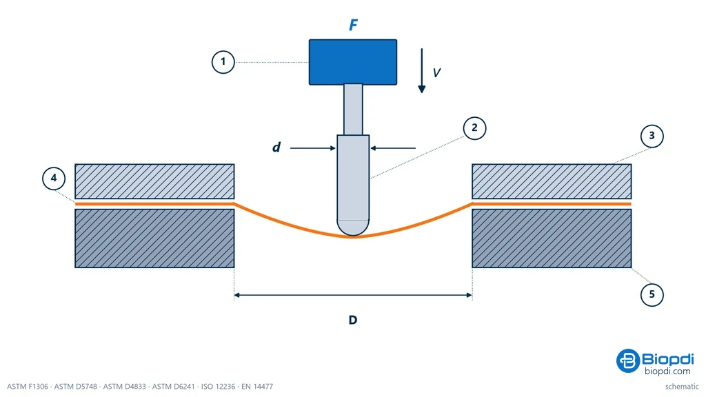
The ratio between D and d matters. With a ring that is too small relative to the probe, the material has no room to stretch and the test turns into a cut at the ring edge; with a large ring, the test measures the membrane more than the tip. F1306, for example, allows another probe as long as the ratio of ring diameter to probe diameter is at least 10:1 (standard text reproduced by fixture suppliers). The general step by step, which each standard details:
- Condition the test specimens at the temperature and humidity of the standard. For film, 23 °C and 50% relative humidity are the usual conditions in plastics laboratories.
- Cut specimens larger than the ring, with no folds or marks in the central region, and note the face that will be turned toward the probe.
- Clamp the specimen between the rings, flat and without pretension, tightening enough that it does not slip during the test.
- Center the probe over the ring and bring it almost into contact with the specimen; zero the force and displacement.
- Set the speed required by the standard and start the advance, recording the force-displacement curve.
- Stop at puncture, identified by the sudden drop in force, and remove the specimen.
- Discard any test with slippage beyond what the standard allows or with failure at the ring edge, and test another specimen.
- Repeat for the number of specimens required by the standard and report the individual values, the mean and the scatter, together with the standard, probe, speed and face tested.
The force-displacement curve
The force-displacement curve of a puncture test starts gently, rises as the material stretches under the probe, reaches a peak and drops sharply when the tip passes through. At first the membrane only flexes and the force increases little per millimeter; then the material starts to be stretched biaxially, the force rises faster, and break occurs at the peak or just after it. In laminates, the curve may show more than one drop, one for each layer that breaks. The graph below shows the curve from Example 1 in this article: the force rises to 18 N at 12 mm and drops at puncture. The shaded area under the curve is the energy W; the dashed triangle is the F·P/2 approximation, which overestimates the energy when the curve starts below the straight line.
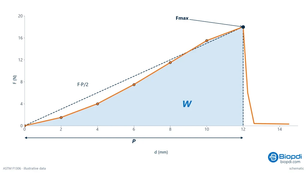
Two details of the curve help diagnose the test. A force that rises and suddenly stops rising, with no sharp drop, while displacement continues, is usually slippage in the ring, not break. A drop in force partway up, followed by a new rise, indicates the break of a layer or a group of fibers, not the end of the test.
Results: maximum force, force at break, penetration and energy
Puncture standards report maximum force, force at break, penetration and energy, but each one chooses its own set. ASTM D5748 determines all four: maximum force, force at break, penetration distance and energy to break. ASTM F1306 determines force, energy and penetration to failure. D4833 and D6241 report the maximum puncture force as an index, and the CBR puncture test also records the plunger displacement. EN 388 uses only the maximum force, converted into a level. Maximum force and force at break can differ: in a very ductile film, the force can drop slightly before the tip passes through, and break occurs below the peak.
Penetration is the answer to searches for "resistance to penetration measuring": it is the probe displacement, measured by the machine crosshead, from contact to break. The test does not use an extensometer, because there is no gauge length on the specimen; the local strain under the tip is not measured, and the result is neither a stress nor a modulus.
Static vs. dynamic puncture
Static puncture pushes the probe slowly, at constant speed in a universal testing machine, and measures force and energy; dynamic puncture drops a dart, a cone or a striker and measures failure energy, the impact curve or the hole diameter. The two families answer different questions. Static puncture compares the resistance of materials under controlled conditions, at speeds of 25 to 500 mm/min. Dynamic puncture reproduces an impact, such as a stone falling onto a geotextile on site or an object striking a film as it falls, at speeds measured in meters per second. The diagram below compares the two setups: on the left, the probe attached to the crosshead of the universal testing machine; on the right, the steel cone of ISO 13433 released from 500 mm.
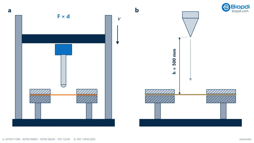
Dynamic tests for films and plastics use other apparatus: the free-falling dart test (ASTM D1709-24 and ISO 7765-1), which looks for the mass or energy that breaks half of the specimens; instrumented impact, in which a striker with a force sensor passes through the specimen at high speed and records the curve (ASTM D3763-23 for rigid plastics, ASTM D7192-26 for films, ISO 6603-2:2023 and ISO 7765-2:2025); and the pendulum (ASTM D3420-21(2026) for film and ISO 3036:2025 for board). In geosynthetics, the dynamic test is the cone drop test of ISO 13433:2025. The table summarizes the differences:
| Aspect | Static | Dynamic |
|---|---|---|
| Equipment | universal testing machine, load cell, ring and probe | drop tower (dart, cone, striker) or pendulum |
| Speed | 25 to 500 mm/min, constant | impact velocity, in m/s |
| Result | Fmax (N), P (mm), W (J) | failure energy or mass, impact curve, hole in mm |
| Standards | F1306, D5748, D4833, D6241, ISO 12236, EN 14477, EN 388, F1342, F2878 | D1709, D3763, D7192, D3420, ISO 6603-2, ISO 7765, ISO 13433, ISO 3036 |
Numbers from the two families do not convert into each other. The DDL laboratory points out that results from different puncture methods do not correlate, and this holds even more between static and dynamic tests, where the strain rate changes the behavior of the polymer. Impact puncture of rigid plastics is covered in more detail in the article on impact testing.
Puncture resistance test standards by material
The puncture resistance test standard depends on the material: F1306 or D5748 for film, D4833 for geomembranes, D6241 or ISO 12236 for geotextiles, EN 388 or ANSI/ISEA 105 for gloves, F1342 or F2878 for protective clothing, and 49 CFR 571.119 for heavy vehicle tires in the United States. What changes from one to another is the probe, the clamp ring opening, the speed and the reported result. The diagram below shows, at the same scale and with a 10 mm scale bar, the profiles of the most widely used probes: from the 0.8 mm tip of EN 14477 to the 50 mm plunger of the CBR puncture test, including the hypodermic needle of F2878.
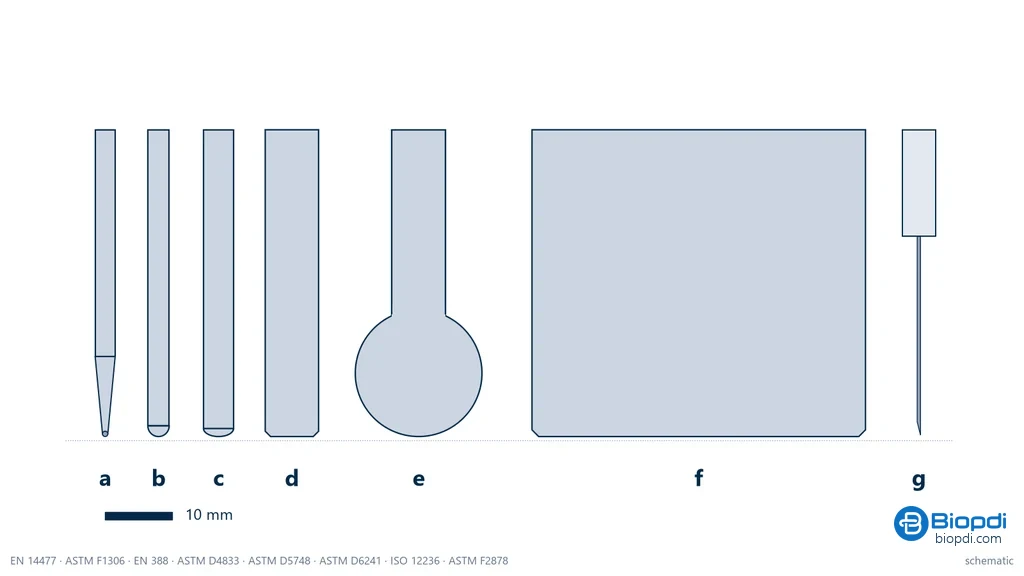
The table lists the main standards, with the edition and status checked in the ASTM store and the ISO catalog on 10/13/2026. Parameters marked with an asterisk come from fixture suppliers, laboratories and agencies that published the values (ZwickRoell, ADMET, Universal Grip, wrapfilmtest, Wisconsin DOT, SATRA, 212 Performance), not from the text of the standard; check them against the purchased standard before setting up the test.
| Standard and edition | Material | Probe and free opening | Speed and result |
|---|---|---|---|
| ASTM F1306-21(2025) | flexible barrier films and laminates | 3.2 mm hemispherical*; 34.9 mm ring* | 25 mm/min*; force, energy and penetration |
| ASTM D5748-26 | stretch wrap film | 19 mm pear-shaped, PTFE-coated*; 102 mm opening* | 250 mm/min*; maximum force, force at break, penetration and energy |
| EN 14477 (2004) | flexible packaging | 0.8 mm tip* | maximum penetration force |
| ASTM D4833/D4833M-07(2026) | geomembranes and related products | 8 mm with 45° chamfer*; 45 mm ring* | 300 mm/min*; maximum force (index) |
| ASTM D6241-22a | geotextiles and related products | 50 mm flat plunger; 150 mm ring* | 50 mm/min*; maximum force and displacement (index) |
| ISO 12236:2026 and ABNT NBR ISO 12236:2013 | geosynthetics with apertures up to 10 mm | 50 mm flat-ended plunger | puncture force (CBR puncture) |
| ISO 13433:2025 | geosynthetics | steel cone dropped from 500 mm | dynamic; hole diameter, mm |
| EN 388:2016+A1:2018 | protective gloves, palm | rounded-tip probe | 100 mm/min*; lowest of 4 results, level 1 to 4 |
| ANSI/ISEA 105-2024 | protective gloves | blunt tip and 25G needle | levels 0 to 5 (blunt tip); needle at 500 mm/min* |
| ASTM F2878-19(2024) | protective clothing | 21, 25 and 28 G hypodermic needles | force for the needle to penetrate |
| ASTM F1342/F1342M-05(2022) | protective clothing | probes A, B and C (methods A, B and C) | force for the probe to penetrate |
| ASTM D5602/D5602M-18(2022) and D5635/D5635M-18(2022) | roofing membranes | as specified in the standard | static (D5602) and dynamic (D5635) |
| 49 CFR 571.119 (FMVSS 119) | tires for heavy vehicles, light trucks, special trailers and motorcycles | hemispherical plunger of 19.05 to 38.10 mm (7.94 mm for motorcycles) | 50 mm/min; breaking energy, J |
On status: ISO 12236:2026 was published in May 2026 and replaced the 2006 edition, now withdrawn; ISO 13433:2025 replaced the 2006 edition, withdrawn in June 2025, and has an amendment under development; at ASTM, D5748 received a new edition in 2026, and D4833/D4833M and F1306 were reapproved in 2026 and 2025. Texts that still cite ISO 12236:2006, ISO 13433:2006 or D5748-95(2019) are out of date. EN 14477 and EN 388 are listed by the edition that suppliers cite; their status at CEN had not been confirmed at the date of this article.
Brazilian standards. ABNT NBR ISO 12236:2013 (CBR puncture), the Brazilian adoption of the 2006 edition of ISO 12236, is listed as current in the Target catalog (a Brazilian standards distributor). ABNT NBR ISO 13433 (cone drop) is cited in its 2013 edition by Booklet 14 of the Geosynthetics Technical Committee of ABINT (the Brazilian nonwovens and technical textiles association) and by DNIT (Brazil's federal transportation infrastructure agency); its current status in the ABNT catalog has not been confirmed. For films, gloves and tires, laboratories in Brazil use the ASTM, ISO and EN standards in the table.
Films and flexible packaging
For film and flexible packaging, slow-rate puncture resistance is measured by ASTM F1306 (barrier films and laminates), ASTM D5748 (stretch wrap film) or EN 14477 (flexible packaging), and the result is reported in N and J. All three drive a probe at constant speed into the film clamped in a ring, but with probes of very different sizes: 3.2 mm, 19 mm and 0.8 mm. For this reason, the values from one cannot be compared with those from another. According to Mecmesin, an equipment manufacturer, packaging films punctured at slow rates typically fall in the 5 to 20 N range, which already points to the load cell: a few tens of newtons, not kilonewtons. Tensile testing of the same film follows ASTM D882, covered in the guide ASTM D882 (tensile testing of plastic films).
ASTM F1306: barrier films and laminates
ASTM F1306-21(2025) characterizes the resistance of flexible barrier films and laminates to slow-rate penetration by a probe, at room temperature, up to puncture, and determines force, energy and penetration. The rationale of the standard is packaging: a product with a sharp edge can breach the barrier and let in gases, odors and contaminants, shortening shelf life. According to ZwickRoell and Universal Grip, the probe has a 3.2 mm diameter hemispherical tip (1.6 mm radius), the ring leaves a 34.9 mm opening (about 35 mm), and the speed is 25 mm/min (1 in/min). Packaging laboratories such as PCL use F1306 to compare medical packaging materials and to evaluate the effect of sterilization and aging on the barrier.
In laminates, the side facing the probe changes the result, and the report must state which side was tested. Battery separators (also searched as "diaphragm") are thin porous films and are also evaluated by slow-rate probe penetration; since none of the standards checked here is a product-specific puncture standard for them, the method, probe and speed should follow the customer's specification and be stated in the report.
ASTM D5748: stretch wrap film
ASTM D5748-26 measures the resistance of stretch wrap film (the stretchable film used to wrap pallets) to penetration by a probe at a single low speed, under biaxial stress, and determines maximum force, force at break, penetration distance and energy to break. The probe is large: in the 95(2019) edition, according to ADMET and wrapfilmtest, fixture suppliers, it is a 19 mm PTFE-coated pear-shaped probe, over a 102 mm opening, with a 152 × 152 mm specimen, a speed of 250 mm/min and at least 5 specimens at 23 °C and 50% relative humidity. The PTFE coating reduces friction, and the wide probe stretches the film biaxially before it breaks, as a box corner does on a pallet. Whether the 2026 edition changed any of these parameters has not been confirmed: check the current standard.
EN 14477: 0.8 mm tip
EN 14477 evaluates the puncture resistance of flexible packaging materials with a fine 0.8 mm tip, which ZwickRoell associates with the "Parker" test, and reports the maximum penetration force. The fine tip represents sharp objects, such as bone fragments in meat packaging or sharp corners of parts; F1306 and D5748, with larger tips, represent rounded objects. A film can perform well in one and poorly in the other, which is why the specification must state which method applies.
Paper, board and films under impact
Paper and board do not follow the film standards. The puncture resistance of board is measured with a pendulum, according to ISO 3036:2025, a dynamic energy test. For film, when the risk is impact (product drop, rough handling), the standards are the ASTM D1709-24 dart drop test and the ASTM D7192-26 instrumented impact test. None of these values can be compared with F1306 or D5748.
Geomembranes and geotextiles
In geosynthetics, static puncture testing of geomembranes follows ASTM D4833, that of geotextiles follows the CBR puncture test (ASTM D6241, ISO 12236 and ABNT NBR ISO 12236), and dynamic puncture testing follows the ISO 13433 cone drop test. The reason there are two static tests is the difference between the products: a geomembrane is a continuous polymer sheet that stretches under a small probe; a geotextile is a woven or nonwoven fabric of fibers, which needs a wide plunger so that many fibers work together and the result is representative. ASTM D4833 makes this explicit: it recommends D6241 for geotextiles and warns that D4833 itself may not be suitable for products with large openings. The name "CBR puncture" comes from the 50 mm piston of the CBR test for soils, from which the plunger inherited its diameter.
ASTM D4833: index puncture test for geomembranes
ASTM D4833/D4833M-07(2026) is an index test for the puncture resistance of geomembranes and related products, which the standard itself considers suitable for acceptance testing of commercial lots. According to the Wisconsin Department of Transportation (WisDOT) report that compared D4833 and D6241, and according to ADMET, the probe is an 8 mm rod with a flat tip and a 0.8 mm 45° chamfer, the ring has a 45 mm opening, the speed is 300 mm/min, 15 tests are run per sample, and no specimen slippage in the ring is allowed. The result is the maximum force.
The most widely used specification for high-density polyethylene (HDPE) geomembrane is GRI-GM13, from the Geosynthetic Institute, which sets a minimum average roll value for D4833 puncture by thickness. The table gives the values for smooth HDPE published by EFI USA, a distributor, based on GRI-GM13; confirm them against the current revision of the specification before using them in a contract:
| Thickness | Minimum puncture (N) | Minimum puncture (lbf) |
|---|---|---|
| 0.75 mm | 196 | 44 |
| 1.00 mm | 267 | 60 |
| 1.50 mm | 400 | 90 |
| 2.00 mm | 534 | 120 |
| 2.50 mm | 667 | 150 |
The force increases in proportion to thickness, about 267 N per millimeter in these values (Biopdi calculation), and stays in the range of hundreds of newtons: a 1 kN to 2 kN load cell is sufficient for the test.
CBR puncture: ASTM D6241, ISO 12236 and ABNT NBR ISO 12236
In the CBR puncture test, a 50 mm flat-ended cylindrical plunger is pushed through the geotextile clamped between two rings, and the maximum force and displacement are recorded. ASTM D6241-22a presents itself as an index test for geotextiles and related products, suitable for lot acceptance. According to WisDOT, the ring has a 150 mm opening, the speed is 50 mm/min, 10 tests are run per sample, and up to 5 mm of slippage is allowed. ISO 12236:2026 measures the force to push the flat-ended plunger through the geosynthetic, on dry and conditioned specimens, and does not apply to products with apertures larger than 10 mm, such as geogrids. In Brazil, ABNT NBR ISO 12236:2013 describes the same test, and Costa and co-authors (Polímeros, 2008) summarize it as a 50 mm piston applying increasing force until the circular specimen clamped between rings breaks.
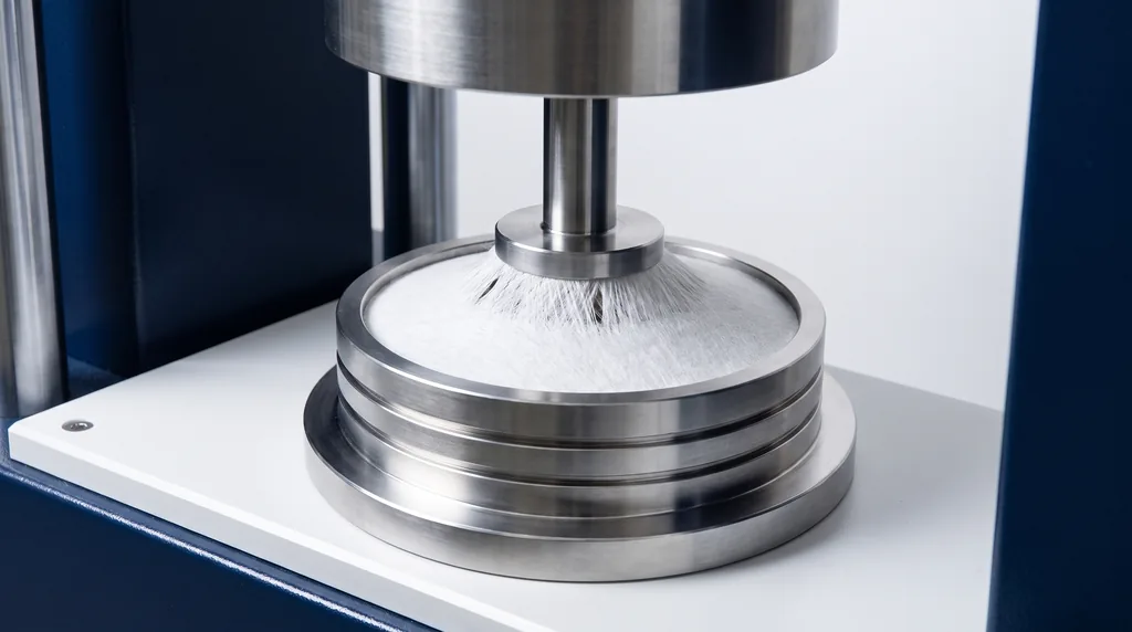
The photo below shows the moment when the 50 mm plunger stretches the nonwoven geotextile clamped in the rings, just before the fibers break: around the plunger, the fibers align in the radial direction, and it is their strength that the test measures.
CBR puncture values are in the kilonewton range. The data sheet of a 305 g/m² polypropylene nonwoven geotextile (Nophadrain ND FV-300) declares a CBR puncture above 3.5 kN per EN ISO 12236. WisDOT studied precisely the correlation between D4833 and D6241 because older geotextile specifications called for D4833; today, ASTM's own recommendation is D6241 for geotextiles.
Cone drop: ISO 13433
ISO 13433:2025 determines the resistance of geosynthetics to dynamic penetration by a steel cone dropped from a fixed height. According to Booklet 14 of the ABINT Geosynthetics Technical Committee, based on NBR ISO 13433, the cone falls from 500 mm onto the specimen clamped in a ring, and the result is the hole diameter in millimeters: the smaller, the better. The test represents sharp stones falling onto the geotextile during placement of fill and crushed stone. The same Nophadrain data sheet declares a hole of about 15 mm in the cone drop test for the 305 g/m² geotextile. ISO warns that the applicability to some products, such as geogrids, geocells, geostrips and geosynthetic barriers, must be evaluated carefully.
Roofing membranes
Roofing waterproofing membranes have their own standards: ASTM D5602/D5602M-18(2022), for static puncture, and ASTM D5635/D5635M-18(2022), for dynamic impact puncture. These are pass/fail tests at a given load or energy level, used to evaluate the membrane against maintenance foot traffic and tools dropped on the roof.
Protective gloves, clothing and footwear
In PPE, the puncture resistance of gloves is rated under EN 388 (levels 1 to 4) or ANSI/ISEA 105 (levels 0 to 5), and that of protective clothing under ASTM F1342 (blunt probe) or ASTM F2878 (hypodermic needle). These scales turn the measured force into a level, which is what appears on the product marking. One caveat applies to all of them: the PPE distributor Magid points out that a laboratory test does not reproduce every real hazard of the workplace, so the level is a basis for comparison, not a guarantee.
EN 388: levels 1 to 4
According to SATRA, a UK PPE testing laboratory, EN 388:2016+A1:2018 measures puncture resistance by pushing a standardized round-tipped probe against specimens taken from the palm of the glove, at 100 mm/min, in a compression testing machine, and records the maximum force. Gloves with several unbonded layers are tested with the layers together, as in use. Four tests are run, and the level comes from the lowest result, not the average: level 1 from 20 N, level 2 from 60 N, level 3 from 100 N and level 4 from 150 N. Level 4 is the maximum in EN 388. Suppliers describe the probe as a 4.5 mm rod with a rounded tip; the exact tip geometry is given in the standard.
ANSI/ISEA 105-2024: levels 0 to 5
The American standard ANSI/ISEA 105-2024 has a blunt-probe puncture scale with six levels, unchanged from the previous edition, according to the brochure of PIP, a glove manufacturer. The table compares the two scales; the limits of ANSI levels 0 to 3 come from PIP, and those of levels 4 and 5 from 212 Performance:
| Level | EN 388 (minimum force) | ANSI/ISEA 105 (range) |
|---|---|---|
| 0 | below 20 N | below 10 N |
| 1 | 20 N | 10 to 19 N |
| 2 | 60 N | 20 to 59 N |
| 3 | 100 N | 60 to 99 N |
| 4 | 150 N (maximum) | 100 to 149 N |
| 5 | does not exist | 150 N or more |
The same level number does not mean the same force in the two standards: a glove reaching 120 N is level 3 under EN 388 and level 4 under ANSI. Texts claiming that EN 388 level 1 goes "up to 20 N" or that level 4 starts "above 100 N" are mixing up the two scales.
Hypodermic needle: ASTM F2878
ASTM F2878-19(2024) measures the force needed for a hypodermic needle to pass through protective clothing material, with three possible needles (21, 25 and 28 G), perpendicular to the surface and with no support behind the specimen. The standard warns that it does not simulate all conditions of use: support stiffness, lubricants and tension in the material change the result. ANSI/ISEA 105 has its own scale for a 25G needle at 500 mm/min, in 2 N steps, with level 5 from 10 N, according to 212 Performance. The order of magnitude is much lower than for the blunt probe: Wikipedia notes that a 25G needle goes through resistant materials with 2 to 10 N, and that needle resistance has little or no correlation with blunt-probe resistance. A glove rated level 4 for blunt puncture can be weak against needles.
ASTM F1342: protective clothing
ASTM F1342/F1342M-05(2022) measures the force needed for a pointed probe to pass through protective clothing material, perpendicular to the surface and with no support behind it, using three protocols: method A uses probe A, for elastomers, textiles and coated materials; method B uses probe B, for textiles and coated materials; method C completes the set. The standard refers snag-type puncture to ASTM D2582-21, a puncture-propagation tear test, and ASTM F2878 refers non-cutting puncture to F1342 itself.
Cut is not puncture: ISO 13997
ISO 13997 measures resistance to cutting by a sharp blade, not to puncture. According to SATRA, a new blade is drawn once across the specimen, over a 20 mm stroke, under several contact loads, to find the force that cuts through; the result becomes the letters A to F in EN 388. It is a cut test and does not assess penetration by points such as needles and thorns. The current edition is 2024. A glove can have a high cut level and a low puncture level, and vice versa.
Footwear with puncture-resistant insoles
To find out whether a boot is puncture resistant, look at the marking of conformity with the safety footwear standard (ISO 20345 series), which states whether the footwear has a puncture-resistant insert and of what type. The insert test pushes a standardized nail against the sole: according to SATRA, a 4.5 mm nail with a conical tip, and EN ISO 22568-4:2021 also allows a 3 mm nail for non-metallic inserts, representing thinner objects.
Tires: the plunger test
The standardized tire puncture resistance test in the United States is the strength test of 49 CFR 571.119 (FMVSS 119), in which a steel plunger with a hemispherical tip is pushed against the tread at 50 mm/min until the tire breaks or the plunger reaches the rim. The standard applies to tires for vehicles with a gross weight above 4,536 kg, to light truck tires with a tread depth of 18/32 in or more, to special trailer tires and to motorcycle tires. The plunger diameter depends on the tire: 19.05 mm for light truck tires, for 17.5 rim diameter or smaller and for 12 rim diameter or smaller; 31.75 mm or 38.10 mm for larger rims, depending on the load range; and 7.94 mm for motorcycle tires.
The tire is mounted on a test rim, inflated to the maximum-load pressure and conditioned at 21 °C for 3 hours. The plunger is applied to a tread element near the centerline, at five points spaced 72° apart (three points 120° apart for tires of rim diameter 12 or smaller). At each point, the force F and the penetration P just before breaking are recorded, and the breaking energy is calculated as W = (F × P / 2) × 10-3, in joules, with F in newtons and P in millimeters. The average of the points must reach the minimum in the standard's table for the tire size and load range.
The test measures the resistance of the tire carcass to a blunt object, not the ability to run while punctured. A "puncture resistant tire", in the bicycle and car markets, is a product claim, based on protective layers or sealant, and not a standardized class. To evaluate a tire, the objective data is the test declared by the manufacturer and the standard used.
How to calculate the puncture test result
The result of a puncture resistance test is calculated directly from the curve: the maximum force is the peak, the penetration is the displacement up to rupture and the energy is the area under the curve up to rupture. There is no "puncture resistance formula" that divides force by thickness; that division is an optional normalization, meaningful only for comparing similar thicknesses of the same material, and it is reported as force per thickness, in N/mm, never as a stress.
The energy is the integral of force over displacement:
W = ∫ F dx (from 0 to P)
With the curve recorded as data points, the integral is calculated with the trapezoidal rule, adding up the area of each interval:
W ≈ Σ (Fi + Fi+1) / 2 × (xi+1 − xi)
With force in N and displacement in mm, W comes out in N·mm; divide by 1,000 to get joules. When only the force and penetration at rupture are known, as in the tire test, the triangular approximation is used, which assumes the force rises in a straight line:
W = F × P / 2
The approximation is exact only if the curve is a straight line. For a film, where the curve starts below the line because the material first just bends, it overestimates the energy, as Example 1 shows. Maximum force and penetration need no calculation: they are read from the curve, and the machine's software reports them directly.
Worked examples of the puncture test
The examples below are illustrative, with numbers consistent with published ranges, and the calculations are Biopdi's.
1. Energy in an F1306-type test (film). The curve of a film, read every 2 mm, gave: 0 N at 0 mm; 1.5 N at 2 mm; 4.0 N at 4 mm; 7.5 N at 6 mm; 11.5 N at 8 mm; 15.5 N at 10 mm; and 18.0 N at 12 mm, where the force dropped sharply (puncture). Maximum force: 18.0 N; penetration: 12 mm. Energy by trapezoids, with 2 mm intervals: (0 + 1.5) + (1.5 + 4.0) + (4.0 + 7.5) + (7.5 + 11.5) + (11.5 + 15.5) + (15.5 + 18.0) = 1.5 + 5.5 + 11.5 + 19.0 + 27.0 + 33.5 = 98.0 N·mm (each term is already (Fi + Fi+1) / 2 × 2 mm) = 0.098 J. With the triangular approximation: 18.0 × 12 / 2 = 108 N·mm = 0.108 J, about 10% higher. The 18 N peak falls within the 5 to 20 N range that Mecmesin cites for packaging films; the right load cell is the smallest in the range, 0.05 kN (50 N), where the peak uses 36% of full scale, and not a 10 kN cell, where it would be 0.18% of full scale.
2. Glove rating under EN 388. Four palm specimens gave 92, 105, 98 and 110 N. The level comes from the lowest value, 92 N. Since 60 ≤ 92 < 100, the glove is level 2. Had the laboratory used the average, (92 + 105 + 98 + 110) / 4 = 101.25 N, it would have declared level 3, one level above the real one. On the ANSI/ISEA 105 scale, the same 92 N would fall in level 3 (60 to 99 N), which shows why the standard must always be stated with the level.
3. Geomembrane to GRI-GM13. The specification calls for 90 lbf of D4833 puncture resistance for 1.5 mm smooth HDPE. In SI: 90 × 4.448 = 400.3 N, that is, 400 N, as in the table. If the lot average in the D4833 test was 452 N, the lot meets the minimum average roll value, with a 13% margin. The full acceptance rule (number of rolls, test frequency) is set by the contract and the specification.
4. Tire to 49 CFR 571.119. At one test point, the tire broke at F = 8,000 N and P = 50 mm. W = (8,000 × 50 / 2) × 10-3 = 200 J. In US units: 200 / 0.1130 = 1,770 in·lbf; with the inch formula, 1,798.6 lbf × 1.969 in / 2 = 1,770 in·lbf, the same value. The tire result is the average of the five points, compared with the minimum in the standard for its size and load range.
5. Choosing the machine for CBR puncture. A geotextile with an expected CBR puncture strength above 3.5 kN calls for a 10 kN machine, where 3.5 kN uses 35% of capacity, with headroom for stronger lots. In the Biopdi line, this is the range of the MBIOI-10-M2 (2 to 10 kN). The D6241 speed, 50 mm/min, and the D4833 speed, 300 mm/min, are within the model's 0.01 to 500 mm/min range.
Puncture, tear, tensile, cupping and cut
Puncture, tear, tensile, cupping and cut tests are different because they load the material in different ways and give results in different units. In puncture, a point goes through a membrane clamped at its edge, in a localized biaxial state. In the tear test, an existing cut or notch propagates. In tension, the whole cross section is stretched in one direction. In cupping, a spherical punch deforms a metal sheet until it cracks, to measure formability. In cutting, a blade slides across the material. The table summarizes:
| Test | Loading | Typical result | Standards |
|---|---|---|---|
| Puncture | point against a membrane clamped in a ring, biaxial | N, mm and J | F1306, D5748, D4833, D6241, ISO 12236, EN 388 |
| Tear | propagation of a cut or notch | N or kN/m | D624, ISO 34-1, D1938, D2261 |
| Puncture followed by tear | point that punctures and tears | N | ASTM D2582-21 |
| Tensile | uniaxial, whole cross section | MPa and % | D882, D412, ISO 527 |
| Cupping | spherical punch on metal sheet | depth to crack, mm | Erichsen |
| Cut | sliding blade | N or level A to F | ISO 13997, EN 388 |
Puncture is also different from compression, even though the machine moves in the same direction: in compression, platens crush the whole specimen; in puncture, only the region under the point is loaded, and the material fails in biaxial tension. Another term that shows up in searches, "puncture voltage", is not even a mechanical test: it is the dielectric breakdown voltage of an insulator, such as a polymer film, measured in an electrical test. The electrical strength of films has its own methods, outside the scope of this article.
Common mistakes in puncture testing
The mistakes that most distort the result, or how it is read:
- Comparing results from different standards. Probe, opening and speed change the number, and different methods do not correlate.
- Using D4833 on geotextiles. ASTM itself recommends D6241 (CBR puncture) for geotextiles.
- Letting the specimen slip in the ring. Slippage lowers the force and increases the apparent penetration; D4833 allows no slippage and D6241 allows up to 5 mm.
- Not stating which face was tested in laminates and coextruded films.
- Testing outside the standard speed. Polymers respond to strain rate.
- Rating gloves by the average under EN 388, instead of the lowest of the four results.
- Mixing up the EN 388 and ANSI/ISEA 105 scales, which use the same level number for different forces.
- Treating ISO 13997 as a puncture test. It measures blade cut.
- Calling force per thickness "strength". Force divided by thickness is only a normalization, in N/mm.
- Using the F·P/2 approximation on a curve that is not straight, overestimating the energy.
- Using a load cell that is too large. An 18 N peak read on a 10 kN cell sits close to the measurement noise.
- Swapping lbf for N when reading US specifications: 90 lbf is 400 N, not 90 N.
- Citing a withdrawn edition, such as ISO 12236:2006, ISO 13433:2006 or D5748-95(2019).
- Reading the index as a design value. D4833 and D6241 are for comparing and accepting lots.
Puncture resistance testing on the Biopdi universal testing machine
The quasi-static puncture resistance tests in the standards table, from 25 to 500 mm/min, are run on a constant-rate-of-extension universal testing machine, with the probe mounted to the load cell on the crosshead and a puncture fixture (clamping ring and probe) built to the geometry of the standard. Biopdi supplies the puncture fixture, with clamping ring and probe, for its universal testing machine, which lists ASTM D4833 puncture testing among the standards it covers, in the compression test group, because the probe moves in the compression direction. The fixture configuration for each standard (probe diameter and tip, ring opening) is defined with our technical team through the contact page. Dynamic tests (falling dart, falling cone, instrumented impact and pendulum) require a drop tower or pendulum, which are not part of the line. The panel below shows the machine, the role of each part in the puncture test and the fixtures in the line related to it.
The universal testing machine in the puncture test
The M2 line has single-column models, from 200 N to 10 kN, and dual-column models, from 5 kN to 1,000 kN. Each part of the machine has a function in the test:
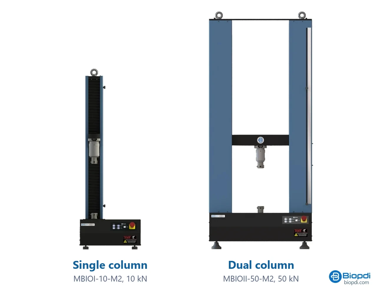
- Moving crosshead advances the probe at the speed set by the standard
- Load cell sized to the peak force, from 0.05 kN up
- Biopdi puncture fixture clamping ring and probe, configured to the standard
- Displacement from the crosshead, no extensometer needed
- BioLab software curve, maximum force and maximum position
- Control panel and emergency stop position and stop the test
Fixtures related to the puncture test
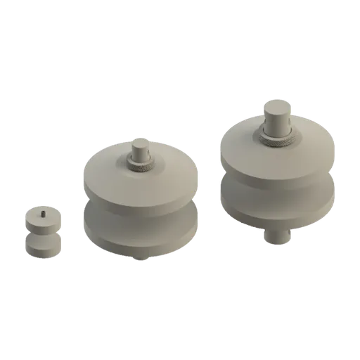
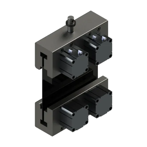
Besides the puncture fixture, the same machine accepts compression platens and the grip for tensile testing of the same geotextile:
The selection rule is to size the load cell to the expected force: tens of newtons for films and gloves, hundreds of newtons for geomembranes, kilonewtons for the CBR puncture test. The line has load cells from 0.05 kN. As for speed, all quasi-static standards in the table, from 25 mm/min (F1306) to 500 mm/min (ANSI needle test), fall within the range of the models, 0.01 to 500 mm/min (up to 600 mm/min on the portable model). Also check that the test space width of the machine (48 mm on the portable model and 150 mm on the MBIOI-10-M2, according to the model pages) accommodates the puncture fixture of the standard. To compare models and configurations, see how to choose a universal testing machine.
| Application | Range | Biopdi model |
|---|---|---|
| Films, packaging, gloves and needle | 200 N to 1 kN; 0.01 to 600 mm/min | MBIOI-1P-M2 portable |
| Geomembranes (D4833), stretch film (D5748) and geotextiles (CBR puncture) | 2 to 10 kN; 0.01 to 500 mm/min | MBIOI-10-M2 |
| Geotextiles and geocomposites with CBR puncture above 10 kN | 5 to 50 kN; 0.01 to 500 mm/min | MBIOII-50-M2 |
Puncture testing is one of the mechanical tests the same universal testing machine performs, alongside tensile, compression, flexural and tear tests; an overview of how the mechanical properties of materials relate to each other helps decide which tests to request along with it.
Other tests and technical references
Tests performed on the Biopdi universal testing machine


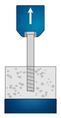


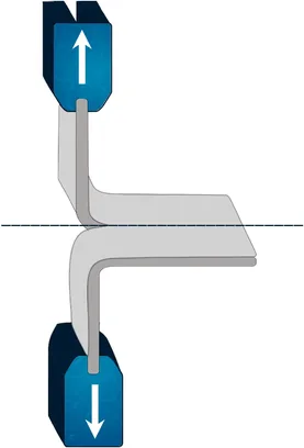
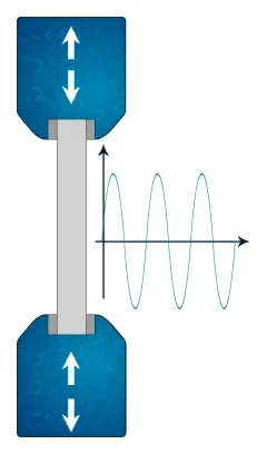

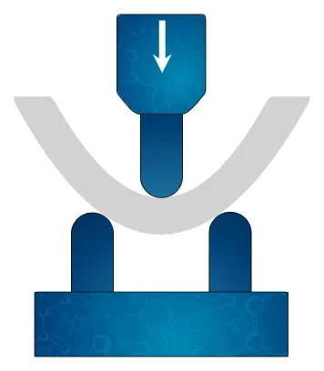


Related technical references
Peel test: 90°, 180°, T-peel and peel strength calculation
The peel test measures the force per unit width needed to separate bonded materials. See 90°, 180° and T-peel, formula, units and ASTM and ISO standards.
Tear test: tear strength testing, standards and calculation
The tear test measures the force to start or grow a tear in rubber, film, fabric and leather. ASTM D624, ISO 34-1, D1938, D2261 standards and calculation.
Axial-torsion test: combined tension and torsion, von Mises and standards
The axial-torsion test applies axial force and torque to the same specimen. See the tube stresses, von Mises, examples, ASTM E2207 and the machine.
Frequently asked questions
What is puncture resistance?
It is the ability of a material to prevent a sharp or round-tipped object from passing through it, measured by a standardized method as maximum force (N), penetration (mm) and energy (J). The value is only valid within the method: the same sample gives different numbers under ASTM F1306, D5748 or EN 388.
What is the unit of puncture resistance?
Newton for force, millimeter for penetration and joule for energy (1 J = 1,000 N·mm). In the United States, lbf (1 lbf = 4.448 N) and in·lbf (1 in·lbf = 0.1130 J) are also used; for gloves, the result becomes a level: 1 to 4 under EN 388 and 0 to 5 under ANSI/ISEA 105.
What is puncture resistance level 4?
Under EN 388, level 4 is 150 N or more, the top of the scale, based on the lowest of four results. Under ANSI/ISEA 105-2024, level 4 ranges from 100 to 149 N, and the maximum is level 5, from 150 N.
Which ASTM standard should be used for puncture resistance?
It depends on the material: ASTM F1306-21(2025) for flexible barrier films and laminates, D5748-26 for stretch film, D4833/D4833M-07(2026) for geomembranes, D6241-22a for geotextiles, F1342/F1342M-05(2022) and F2878-19(2024) for protective clothing, and D1709-24 or D7192-26 for impact puncture of film (editions checked on 10/13/2026).
How is a puncture resistance test performed?
The conditioned test specimen is clamped between two rings with no slack, and a probe attached to the load cell advances against its center at the speed set by the standard (25 to 500 mm/min), recording force and displacement until puncture. The test is repeated on the number of specimens required by the standard, and maximum force, penetration and energy are reported.
How is puncture energy calculated?
As the area under the force × displacement curve up to failure, summed by trapezoids: with force in N and displacement in mm, the result is in N·mm and is divided by 1,000 to give joules. The approximation W = F × P / 2, used in the US tire test, is only exact if the curve is a straight line.
What is the difference between static and dynamic puncture?
In static puncture, the probe advances slowly at constant speed on a universal testing machine, and force, penetration and energy are measured (F1306, D4833, D6241). In dynamic puncture, a dart, cone or striker falls on or strikes the material, and failure energy, impact curve or hole diameter is measured (D1709, D3763, ISO 13433). Results from the two cannot be converted into each other.
How is the puncture resistance of a tire evaluated?
In the United States, by the plunger test of 49 CFR 571.119 (FMVSS 119), for tires of heavy vehicles, light trucks, special trailers and motorcycles: a hemispherical plunger of 19.05 to 38.10 mm (7.94 mm for motorcycles) advances at 50 mm/min until the tire breaks, at five points, and the average breaking energy, W = (F × P / 2) × 10-3 J, is compared with the minimum in the standard.
Is puncture resistant the same as puncture proof?
No. "Puncture resistant" means the material reached a minimum value in a defined test, such as 150 N at EN 388 level 4; "puncture proof" suggests that nothing can pass through it, which no puncture standard guarantees. The same applies to paint protection films (PPF): no puncture standard specific to this product has been confirmed, and any declared value can only be compared with another value measured by the same film method.
What is ASTM F2183?
It was the small punch test standard for ultra-high molecular weight polyethylene used in surgical implants, withdrawn by ASTM in 2017. The current small punch method for this material is ASTM F2977-20; it is not a puncture test for films or PPE.
Does needle puncture resistance track blunt probe puncture resistance?
Little or not at all. A 25G needle goes through resistant materials with 2 to 10 N, while the blunt probe of EN 388 reaches 150 N at level 4; needles have their own test, ASTM F2878-19(2024), with 21, 25 and 28 G needles.
Which machine measures puncture resistance?
Static methods use a constant-rate-of-extension universal testing machine, with a load cell sized to the peak force and a puncture fixture (ring and probe) built to the geometry of the standard; Biopdi supplies both the machine and the puncture fixture. SATRA describes the EN 388 test on a compression testing machine. Dynamic methods use a drop tower or pendulum, which is different equipment.