
ASTM E8/E8M and ISO 6892-1 are the two standards for tensile testing of metallic materials at room temperature. The current editions are ASTM E8/E8M-25, ISO 6892-1:2019 and, in Brazil, ABNT NBR ISO 6892-1:2024, which received a corrected version in July 2026. Both measure the same properties (yield strength, tensile strength, elongation and reduction of area), but they require different things: the gauge length of the test specimen, how the testing speed is controlled and its tolerance, the symbols, the rounding, and the standards that qualify the testing machine and the extensometer. In practice, the strength values measured by the two standards agree, and the elongation values do not.
In short:
- Round specimen: the gauge length for elongation is 4 diameters in E8 (inch-pound), 5 diameters in E8M (SI) and 5.65 times the square root of the cross-sectional area in ISO, which also works out to 5 diameters.
- Speed: the nominal value before yield is the same in both standards; ISO allows ±20% and E8 Method B allows about ±40% (in E8/E8M-09, the edition we consulted).
- Machine and extensometer: ISO 7500-1 and ISO 9513 in the ISO family; ASTM E4 and ASTM E83 in the ASTM family.
What each standard is and where it applies
The test itself is the same in both families: a test specimen with a known original cross-sectional area, S0, is subjected to an increasing axial tensile force until it fractures, and the machine records force and extension. Before the test, two marks are made on the reduced section, separated by the original gauge length L0, the base over which elongation is measured. The maximum force gives the tensile strength; the beginning of the curve gives the yield strength; the marks, after fracture, give the elongation. The curve, the step-by-step procedure, the use of the extensometer and the basic calculations are covered in the article on the tensile test. Here the subject is what each standard requires and where they differ.
- ASTM E8/E8M-25 (active since August 26, 2025): test methods for tension testing of metallic materials in any form, between 10 and 38 °C. It is a dual-designation standard: E8 uses inch-pound units and E8M uses SI units.
- ISO 6892-1:2019: third edition of the international standard for tensile testing of metals at room temperature, between 10 and 35 °C (23 ± 5 °C when the test requires controlled conditions). It replaced the 2016 edition.
- ABNT NBR ISO 6892-1:2024: second edition, dated April 21, 2024, an identical Brazilian adoption of ISO 6892-1:2019, issued by committee ABNT/CB-004, 79 pages. It cancels and replaces the 2013 edition and received Erratum 1 and the corrected version on July 13, 2026. Anyone buying the standard in Brazil today should ask for the corrected version.
- ASTM A370-26 (active since May 21, 2026): test methods and definitions for mechanical testing of steel products, covered in its own section further on.
Test specimens and gauge length
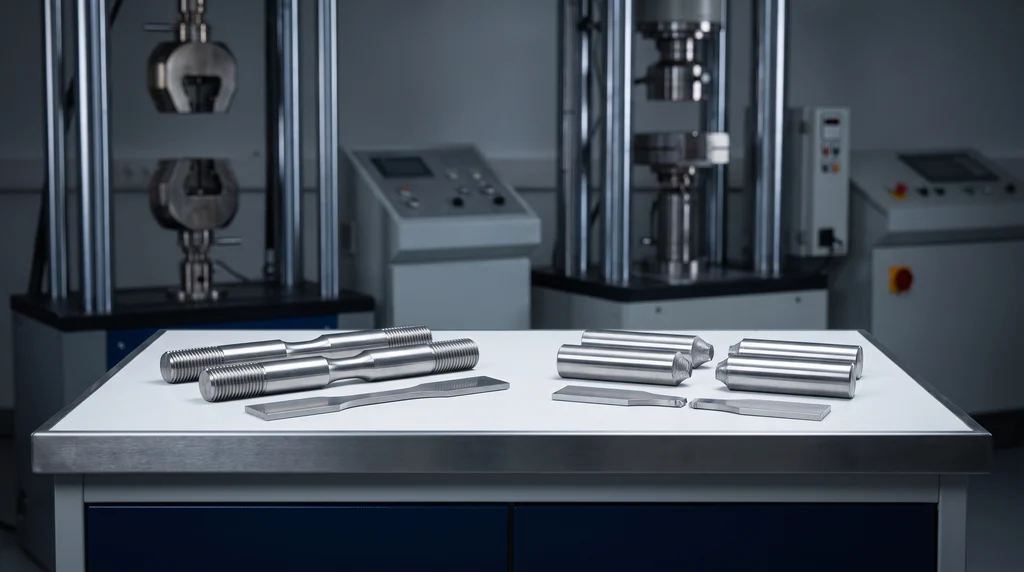
The photo shows machined metal test specimens: the round ones have threaded ends and a reduced section in the middle, and the flat one is cut from sheet. Both standards define the dimensions of these two types, and this is where the differences between them begin.
Round: 4D, 5D and 5.65√S0
ISO 6892-1 prefers the proportional test specimen, in which L0 grows with the cross section: L0 = k·√S0, with k = 5.65 and L0 of at least 15 mm. Since the area of a round specimen is π·d0²/4, the calculation 5.65·√S0 gives 5.01·d0: in practice, five diameters. When the cross section is too small for the 15 mm, k = 11.3 or a fixed L0, such as 80 mm, is used. Proportionality makes it possible to compare the elongation of test specimens of different sizes.
In E8/E8M, the gauge length of the round specimen depends on the unit system of the standard. The standard specimen is 12.5 mm in diameter; under E8, the gauge length is 50 mm (4D); under E8M, 62.5 mm (5D). ASTM itself states that the gauge length is the most significant difference between E8 and E8M test specimens. The smaller round specimens follow the same rule: diameters of 9 mm and 6 mm give gauge lengths of 36 and 24 mm in E8 and of 45 and 30 mm in E8M. These dimensions were checked in the 2009 edition (E8/E8M-09); the 4D and 5D rule is confirmed in the scope of E8/E8M-25.
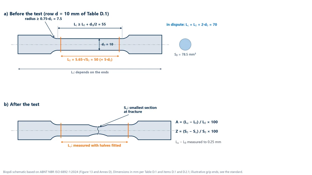
ISO also specifies what surrounds L0 on the machined round specimen, in Annex D: a parallel length of at least L0 + d0/2, or L0 + 2d0 in case of dispute, and a transition radius of at least 0.75·d0. The diagram below applies these rules to the 10 mm round specimen from the table in the standard (L0 = 50 mm and Lc of at least 55 mm) and shows, at the bottom, what is measured after fracture: Lu, with the halves fitted together, and the minimum cross section Su, which give A and Z.
Sheet: fixed width and gauge length
For sheet, both standards use a fixed L0, with no proportionality. In E8/E8M-09, the sheet-type specimen is 12.5 mm wide with a 50 mm gauge length, for thicknesses up to 19 mm, and the plate-type specimen is 40 mm wide with a 200 mm gauge length, for thick plate; check the dimensions in E8/E8M-25. ISO covers thin products, from 0.1 to 3 mm, in Annex B, and Type 2 in that annex is 20 mm wide, with an 80 mm gauge length and a 120 mm parallel length (recommended; the minimum is 90 mm). Above 3 mm, the proportional rule generally applies again (Annex D).
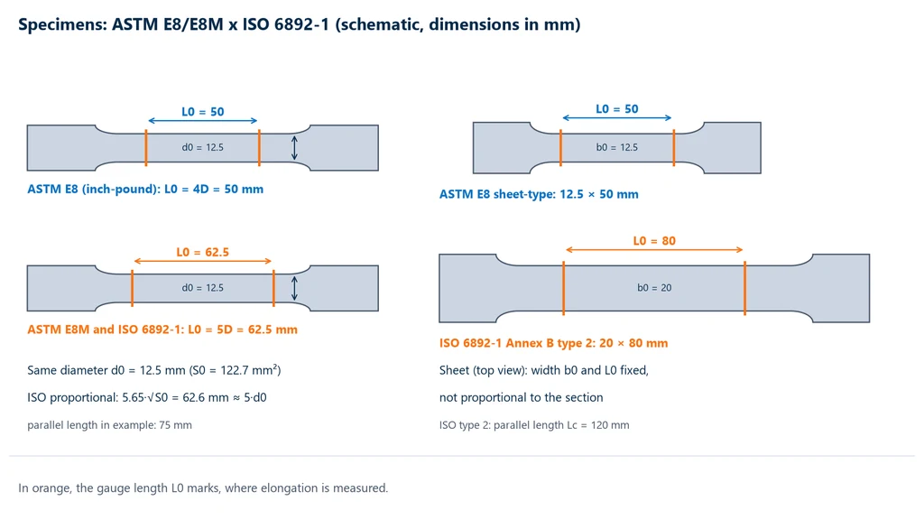
The diagram below compares the two pairs: on the left, the same 12.5 mm round specimen with the 50 mm gauge length of E8 and the 62.5 mm gauge length of E8M and ISO; on the right, the 12.5 × 50 mm sheet specimen of E8 and the 20 × 80 mm ISO Type 2. The orange marks delimit L0.
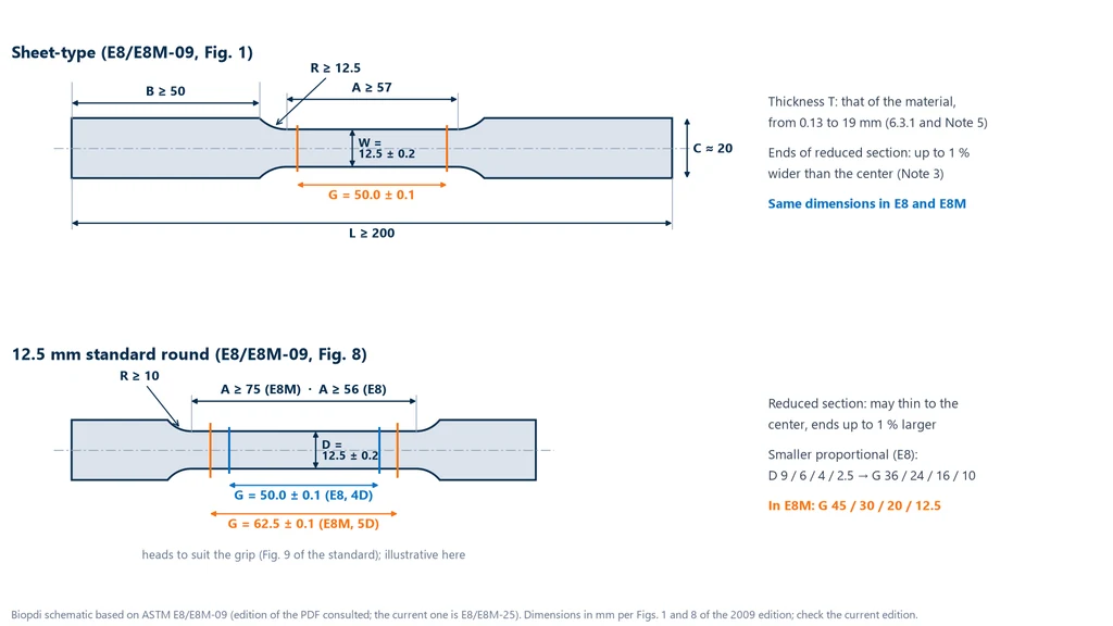
For those who machine the test specimen, the next diagram gives the complete dimensions, with tolerances, of the two standard E8 formats: the sheet-type specimen and the 12.5 mm round specimen, with the 50 mm gauge length of E8 and the 62.5 mm gauge length of E8M. They were taken from the 2009 edition of the standard, the one we consulted in PDF. The current edition is E8/E8M-25, and the dimensions should be checked against it before releasing a manufacturing drawing, as the footnote of the image below indicates.
In all cases, the area used is measured, not nominal. A 1% error in S0 becomes a 1% error in every stress value, so the diameter, or the width and thickness, is measured with a micrometer at more than one location.
Speed control: ISO methods A1, A2 and B and E8 methods A, B and C
The yield strength of many steels depends on the strain rate: speeding up the test increases the measured value. That is why both standards specify the speed up to yield more strictly than after it. They use different names for similar ideas, and the letters do not match.
ISO 6892-1 has two methods:
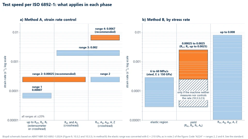
- Method A, strain rate control. In A1, the machine controls strain in closed loop, using the extensometer signal. In A2, it keeps the crosshead speed constant, calculated from the parallel length: vc = Lc × ė, where Lc is the parallel length and ė is the target rate. The rates come in ranges, all with a tolerance of ±20%: range 1, 0.00007 s⁻¹; range 2, 0.00025 s⁻¹; range 3, 0.002 s⁻¹; range 4, 0.0067 s⁻¹. For Rp and ReH, ranges 1 or 2 are used; for ReL and Ae, ranges 2 or 3, by crosshead; for tensile strength and elongation, ranges 2, 3 or 4 (range 2 recommended before yield and range 4 after).
- Method B, stress rate control. In the elastic range, 6 to 60 MPa/s for materials with a modulus of elasticity of at least 150 GPa, such as steel, and 2 to 20 MPa/s below that, such as magnesium, aluminum alloys, brass and titanium (examples given by the standard itself).
The ISO test report summarizes the choice in a code: "A224" means method A, range 2 for ReH or Rp, range 2 for ReL and range 4 for Rm and elongation.
In method A, range 2 is recommended up to yield and also during the yield plateau, when ReL is measured; after yield, range 4 is recommended, and range 3 can be used for both phases. In method B, the stress rate is only imposed in the elastic range: during yielding, the strain rate does not exceed 0.0025 s⁻¹ (for ReL, it stays between 0.00025 and 0.0025 s⁻¹) and, after yield, it goes up to 0.008 s⁻¹. The diagram below shows what applies in each phase of the test in both methods.
E8/E8M has three methods for the portion up to yield. The values below are those of E8/E8M-09, the edition we consulted; the current edition is E8/E8M-25, and the rates should be checked against it before setting up a test method:
- Method A, stress rate: 1.15 to 11.5 MPa/s.
- Method B, strain rate measured by the extensometer: 0.015 ± 0.006 mm/mm/min.
- Method C, crosshead speed: 0.015 ± 0.003 mm/mm/min multiplied by the length of the reduced section.
After yield, for materials with an expected elongation above 5%, E8/E8M-09 accepts 0.05 to 0.5 mm/mm/min.
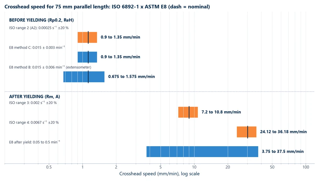
The comparison has a point few people notice: 0.015 min⁻¹ divided by 60 is exactly 0.00025 s⁻¹, ISO range 2. The nominal value is the same; what changes is the tolerance. In E8/E8M-09, method C allows ±0.003 min⁻¹, that is, ±20%, like ISO; method B allows ±0.006 min⁻¹, about ±40%. In terms of control, E8 method B corresponds to ISO A1, and method C to A2. The stress rate ranges, however, only overlap between 6 and 11.5 MPa/s: a steel test at 20 MPa/s meets ISO and does not meet E8.
The chart below shows the ranges converted into crosshead speed for a parallel length of 75 mm, the one in the worked example further on. Before yield, ISO range 2 and E8 method C fall in the same interval, and E8 method B is wider. After yield, ISO range 4, around 30 mm/min, fits within the E8 range. E8 method B is shown converted to crosshead speed for comparison only: in the standard, its rate is the one measured by the extensometer.
With crosshead control (A2 or method C), the actual rate in the test specimen is lower than the nominal rate, because part of the displacement is deformation of the machine and the grips; for rate-sensitive materials, closed-loop control by extensometer is more repeatable. Yielding itself is covered in the article on the elastic limit.
Yield, tensile strength and elongation: what each standard calls what
The properties are the same; the names and some criteria differ. ISO uses symbols (Rp0.2, ReH, A); ASTM uses spelled-out terms (offset yield strength, elongation).
Yield strength
In a material without a yield point, both standards use the offset method: draw a line parallel to the elastic portion, offset by a specified plastic strain, and read the stress where it intersects the curve. With 0.2%, ISO calls the result Rp0.2; E8 calls it the 0.2% offset yield strength. ISO also defines Rt, the stress at a specified total extension, which corresponds to the E8 extension-under-load method used in some tube and bar specifications.
In steel with a yield point, such as rolled low-carbon steel, the force drops after the first peak and fluctuates along a plateau. ISO defines two values: ReH, the upper yield strength, which is the stress at the peak before the first drop, and ReL, the lower yield strength, the lowest stress on the plateau, disregarding the initial transient effect. The length of the plateau is Ae. E8 has the same two values under other names: upper yield strength (UYS) and lower yield strength (LYS), read from the recorded diagram with the same logic (first peak; lowest value excluding transients), and the plateau length is the yield point elongation (YPE), per E8/E8M-09. Which value goes on the certificate is set by the product specification, not by the test standard.
Tensile strength, elongation and reduction of area
Tensile strength is the same in both standards: Rm = Fm/S0, the maximum force divided by the original cross-sectional area. Reduction of area, the percentage decrease in area at the neck, is Z in ISO and reduction of area in E8; the phenomenon is covered in the article on necking.
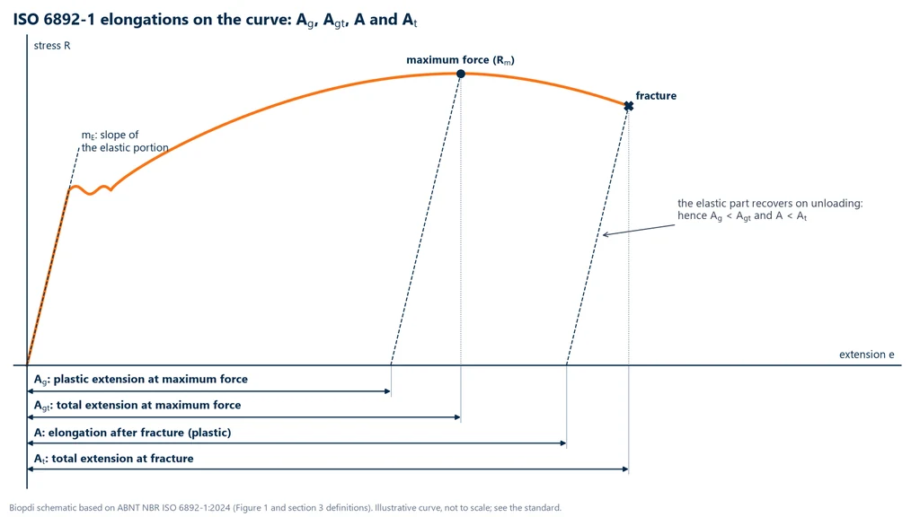
Elongation after fracture is A = (Lu − L0)/L0 × 100, with Lu measured by fitting the two halves together. ISO writes the gauge length into the symbol: A (proportional, 5.65√S0), A11.3, A50mm, A80mm. E8 reports "elongation in 50 mm" or "in 4D". ISO also defines elongation at maximum force: Agt, total, including the elastic part, and Ag, the plastic part only. Both measure ductility before necking and do not depend on the gauge length in the same way as A.
The two maximum-force values come from the same point on the curve: Agt is the total extension read there, and Ag is what remains after subtracting the elastic part, using a line parallel to the slope of the elastic portion. The same logic applies at fracture: At is the total extension at the moment of fracture, and A is the plastic part, the one measured by fitting the halves together. The diagram below locates all four on the curve.
Rounding
ISO 6892-1 recommends (section 22) rounding the results, unless the product standard says otherwise: stresses to the nearest whole MPa, Ae to 0.1%, other elongations to 0.5% and reduction of area to 1%. E8 says to follow the material specification and ASTM E29; in their absence, E8/E8M-09 recommends stresses to 1 MPa up to 500 MPa, to 5 MPa between 500 and 1,000 MPa and to 10 MPa above that, and reduction of area to 0.5% below 10% and to 1% above. Close to the specified minimum, the rounding rule decides acceptance and must be stated in the report.
Machine and extensometer: ISO 7500-1, ISO 9513, ASTM E4 and ASTM E83
The test standards refer to their own standards for force and strain measurement, and each family has its own: a calibration certificate from one family does not prove compliance with the other.
- Force, ISO family: ISO 6892-1 requires a machine verified to ISO 7500-1:2018 (ABNT NBR ISO 7500-1:2023 in Brazil), class 1 or better. The class applies only within the verified range of each load cell.
- Force, ASTM family: E8 requires a machine verified to ASTM E4-24, whose criterion is an error of up to ±1% within the verified range. E4 itself warns that, once calibration uncertainty is added, the actual deviation can exceed 1%.
- Extensometer, ISO family: ISO 9513:2012 (ABNT NBR ISO 9513:2013 in Brazil), with classes 0.2, 0.5, 1 and 2. ISO 6892-1 requires class 1 for Rp and Rt and accepts class 2 for properties at extensions above 5%, such as Agt (section 9). ReH and ReL are determined from force alone.
- Extensometer, ASTM family: ASTM E83-25, with classes A, B-1, B-2, C, D and E. E8/E8M-09 requires class B-2 or better for yield strength.
In both families, yield strength cannot be taken from crosshead displacement: it includes grip slack and machine deflection. The extensometer gauge length must also fit within the specimen gauge length: a 50 mm extensometer suits the 12.5 mm E8 round specimen; for the ISO 62.5 mm, yield is measured with a compatible extensometer and final elongation from the gauge marks. For Rp, ISO recommends an extensometer gauge length between half of L0 and about 90% of the parallel length; for properties at or after maximum force, close to L0 (8.3).
Summary: ASTM E8/E8M vs. ISO 6892-1 side by side
The table brings together what the previous sections explained, for quick reference when setting up the test method or reading a test report:
| Item | ASTM E8/E8M-25 | ISO 6892-1:2019 and NBR ISO 6892-1:2024 |
|---|---|---|
| Temperature | 10 to 38 °C | 10 to 35 °C (23 ± 5 °C controlled) |
| Units | E8: inch-pound; E8M: SI | SI |
| 12.5 mm round specimen | L0 = 50 mm (4D, E8) or 62.5 mm (5D, E8M) | L0 = 5.65√S0 ≈ 62.5 mm (5d0) |
| Sheet | 12.5 × 50 mm (sheet); 40 × 200 mm (plate) | up to 3 mm: Annex B, type 2, 20 × 80 mm |
| Speed up to yield | A: 1.15 to 11.5 MPa/s; B: 0.015 ± 0.006 min⁻¹; C: 0.015 ± 0.003 min⁻¹ (E8/E8M-09) | A1/A2: 0.00025 s⁻¹ ±20% (or 0.00007); B: 6 to 60 MPa/s (E ≥ 150 GPa) |
| Speed after yield | 0.05 to 0.5 min⁻¹ (E8/E8M-09) | A: 0.002 or 0.0067 s⁻¹ ±20% (range 4 recommended); B: up to 0.008 s⁻¹ |
| Yield | offset, extension under load, diagram | Rp, Rt, ReH, ReL |
| Elongation | with the gauge length stated (50 mm, 4D) | A, A11.3, A80mm, Ag, Agt |
| Rounding | per the specification; otherwise 1/5/10 MPa depending on the range (E8/E8M-09) | recommended: 1 MPa; Ae 0.1%; A 0.5%; Z 1% |
| Machine | ASTM E4 (±1%) | ISO 7500-1, class 1 |
| Extensometer | ASTM E83, class B-2 for yield (E8/E8M-09) | ISO 9513, class 1 for Rp and Rt; class 2 above 5% |
Worked example: the same test specimen under both standards
A lot of cold-drawn 1020 steel bar needs test reports for two customers, one requiring ISO 6892-1 and the other ASTM E8. The lab machines a round specimen with d0 = 12.50 mm (measured) and a 75 mm parallel length, scribes marks every 12.5 mm so both gauge lengths can be measured, and tests with an extensometer. Readings: force at the 0.2% offset of 42.95 kN and maximum force of 51.55 kN. After fracture, with the halves fitted together, the 62.5 mm gauge length measures 71.9 mm and the 50 mm one, centered on the fracture, measures 58.6 mm.
- Area: S0 = π × 12.50² / 4 = 122.72 mm².
- Gauge lengths: ISO, L0 = 5.65 × √122.72 = 5.65 × 11.078 = 62.59 mm, marked as 62.5 mm (5d0); E8M, 5D = 62.5 mm; E8, 4D = 50.0 mm.
- Yield: 42,950 / 122.72 = 349.99, rounded to 350 MPa, the same under both standards.
- Tensile strength: 51,550 / 122.72 = 420.07, rounded to 420 MPa, the same under both standards.
- Elongation per ISO (and E8M): A = (71.9 − 62.5) / 62.5 × 100 = 15.04, rounded to 15.0%.
- Elongation per E8 (4D): (58.6 − 50.0) / 50.0 × 100 = 17.2%, reported as elongation in 50 mm.
Stresses do not depend on the gauge length and come out identical, with values consistent with a cold-drawn 1020 steel. Elongation changes by 2.2 percentage points without any change in the material, for the reason explained in the next section.
Crosshead speed, for Lc = 75 mm. ISO range 2 (A2): 75 × 0.00025 = 0.01875 mm/s = 1.125 mm/min, with ±20%, from 0.90 to 1.35 mm/min. E8 method C: 0.015 × 75 = 1.125 mm/min, from 0.90 to 1.35 mm/min. After yield, ISO range 4 gives 75 × 0.0067 = 0.5025 mm/s, about 30 mm/min, and E8 accepts from 0.05 × 75 = 3.75 to 0.5 × 75 = 37.5 mm/min. A program of 1.125 mm/min up to yield and 30 mm/min afterward meets both standards, but each report cites its own. If the lab prefers stress rate, the range common to both standards is 6 to 11.5 MPa/s, which for this area gives 0.74 to 1.41 kN/s.
Machine capacity. The maximum force was 51.6 kN. A 50 kN machine has no margin even for rolled 1020 (380 MPa × 122.72 mm² = 46.6 kN, 93% of capacity), and the cold-drawn bar exceeds it. This specimen calls for the 100 to 200 kN range. If the lab only has the 50 kN machine, it can use the smaller 6 mm E8 round specimen (S0 = 28.27 mm²), which fractures at 420 × 28.27 = 11.9 kN, with a 24 mm gauge length under E8 and 30 mm under ISO (5.65 × √28.27 = 30.0 mm).
Why elongation under one standard is not valid under the other
Elongation after fracture has two components. The first is uniform: up to maximum force, the entire gauge section stretches evenly, and this component, as a percentage, is the same for any gauge length. The second is localized: after maximum force, deformation concentrates in the neck, which adds a few millimeters to the length, almost independently of the gauge length. Divided by a short gauge length, this fixed component weighs more; by a long one, it weighs less. That is why, in the same material, A50mm is greater than A62.5mm, which is greater than A80mm or A200mm.
The chart below shows this effect with the numbers from the example, using an illustrative model: a uniform component of 6.4% and a neck that adds about 5.4 mm. The curve passes through 17.2% at the 50 mm gauge length and 15.0% at 62.5 mm, and would drop to about 9% at a 200 mm gauge length.
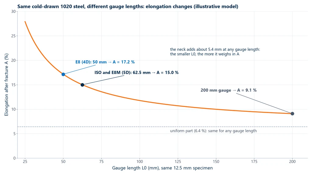
The consequence for buyers and inspectors is direct: an ASTM certificate showing 17% in 50 mm does not prove that the material meets an ISO specification requiring 15% in 5.65√S0, nor the other way around, because the two numbers measure different things. There is a conversion standard: ISO 2566-1:2021 converts elongations between gauge lengths for carbon and low-alloy steels with Rm from 300 to 700 MPa, and ISO 2566-2 covers austenitic steels. The conversion has limits: part 1 does not apply to cold-worked steel, such as the cold-drawn bar in the example, nor to quenched and tempered steel. Outside these limits, the safe route is to test to the standard the specification requires, or to mark both gauge lengths, as in the example.
ASTM A370: why the steel certificate cites it
Anyone receiving steel plate, tube, rebar or fasteners under an American specification sees A370 on the certificate, not E8. A370-26 brings together the methods and definitions for mechanical testing of steel, stainless steel and related alloy products: tension, bend, hardness (Brinell, Rockwell and portable) and impact. It has ten annexes for specific products, such as bar, tube, fasteners and wire, and ASTM product specifications cite it to demonstrate the required properties.
For tension, A370 works on the same principles as E8, which E8/E8M-25 itself lists as a related document; what A370 adds are the test specimens and rules for each steel product. For metals other than steel, such as aluminum, copper and titanium, A370 does not apply, and the tensile reference is E8/E8M.
Which standard to use
The choice is not technical, it is contractual: the test report follows the standard required by the material specification or the purchase order. In the absence of an explicit requirement, the practical rule is:
- ABNT specification (Brazilian standards), supply in Brazil or European specification: ABNT NBR ISO 6892-1:2024 (or ISO 6892-1:2019).
- Steel product under an ASTM specification (plate, tube, bar, fastener): ASTM A370, with tension by the E8 method.
- Other metal under an American standard, or a contract that cites E8: ASTM E8 or E8M, stating which.
- Customer requiring both: one test specimen with both gauge lengths marked and a speed program that satisfies both, as in the example; the reports are issued separately.
Common mistakes in applying the standards
Almost all application mistakes come from treating the two standards as interchangeable:
- Reading "E8" as always 4D. E8M is 5D; the report must state the gauge length.
- Comparing elongations from different gauge lengths (A50mm, A, A80mm) without conversion, or converting outside the limits of ISO 2566-1.
- Citing a superseded edition. E8-11, E8-13, ISO 6892-1:2009 and 2016 and NBR ISO 6892-1:2013 are still in circulation; the current ones are E8/E8M-25, ISO 6892-1:2019 and NBR ISO 6892-1:2024.
- Using the E8 method B tolerance in an ISO test. ±40% does not fit within the ISO ±20%.
- Measuring Rp0.2 from the crosshead or with an extensometer outside the required class (class 1 of ISO 9513; B-2 of E83).
- Changing the speed before yield has been determined. ReH and Rp change with the rate.
- Using A370 for a nonferrous metal. It covers steel products.
- Testing at 36 or 38 °C and reporting it as the ISO normal condition. Above 35 °C, ISO requires the temperature to be recorded and reported; in E8, the range goes up to 38 °C.
- Omitting the speed code and the rounding rule from the ISO report.
Testing equipment for both standards
Both standards are run on a universal testing machine: the crosshead applies the tensile force at the programmed speed, the load cell measures the force, the extensometer measures the strain over the gauge length, and the software calculates the results. For the Biopdi M2 line, the product page states a class 1 load cell per ISO 7500-1 (ABNT NBR ISO 7500-1:2023 in Brazil), and its list of metals standards includes ISO 6892-1 (ABNT NBR ISO 6892-1:2024 in Brazil) and ASTM E8/E8M-25. The panel below shows the machine, the role each part plays in testing metals, and the fixtures used.
The universal testing machine in tensile testing of metals
The M2 line includes single-column models from 200 N to 10 kN and dual-column models from 5 kN to 1,000 kN. In a test to ISO 6892-1 or E8, each part has a job:

- Moving crosshead speed in the ISO range or per the E8 method
- Load cell class 1, ISO 7500-1 (NBR ISO 7500-1:2023)
- Grips wedge grips for plain rounds and sheet; threaded grips
- Extensometer Rp0.2, Rt and Ae over the gauge length
- BioLab software phase-by-phase program, results and report
- Control panel and emergency stop positions and stops the test
Fixtures for tensile testing of metals
The fixtures below are mounted on the same machine, depending on the test specimen:
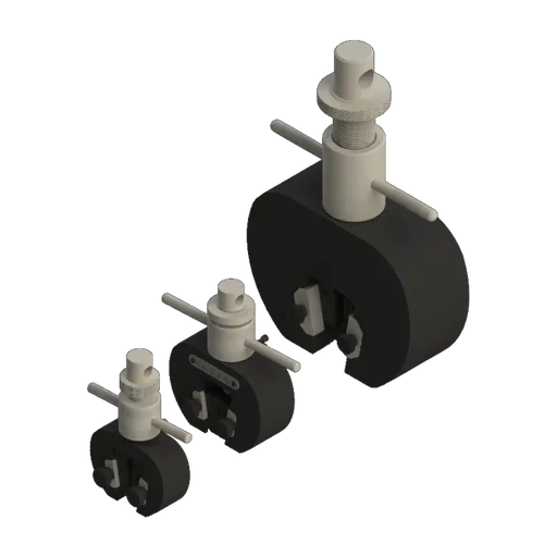
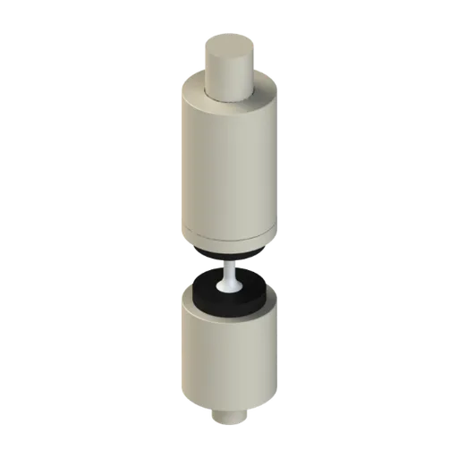
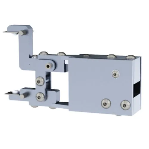
For thin sheet and small rounds, such as the 6 mm specimen in the example, the recommended range is the 5 to 50 kN machine; for the 12.5 mm steel round, bars and sections, the 100 to 200 kN range. The test method is set up in the BioLab software, which generates the report in PDF, HTML or CSV. How to size the machine in general is covered in our guide to the universal testing machine. To configure the machine for your standards, request a quote.
Standards cited
The table lists the standards in this guide with their current edition, checked on September 30, 2026 in the ASTM store, the ISO catalog and the Target (ABNT) listing:
| Standard | Subject | Current edition |
|---|---|---|
| ASTM E8/E8M | tension testing of metallic materials | E8/E8M-25 |
| ISO 6892-1 | tensile testing of metals at room temperature | 2019 |
| ABNT NBR ISO 6892-1 | Brazilian adoption of ISO 6892-1 | 2024, corrected version July 2026 |
| ASTM A370 | mechanical testing of steel products | A370-26 |
| ISO 7500-1 and ABNT NBR ISO 7500-1 | verification of machine force | 2018 and 2023 |
| ASTM E4 | verification of machine force | E4-24 |
| ISO 9513 and ABNT NBR ISO 9513 | calibration of extensometers | 2012 and 2013 |
| ASTM E83 | verification and classification of extensometers | E83-25 |
| ISO 2566-1 | conversion of elongation values, carbon and low-alloy steels | 2021 |
Other tests and technical references
Tests performed on the Biopdi universal testing machine



















Related technical references
Weld test specimen: tensile and bend tests per ASME IX, AWS and ISO
Weld test specimen: how to cut, machine and run tensile and bend tests per ASME IX and ISO 15614-1, with the 3 mm and 95% criteria and examples.
Extensometer and strain gauge: what they are, how they work, types and use in the tensile test
Extensometer and strain gauge: the bonded strain sensor (ΔR/R = GF·ε, GF ≈ 2), bridges, rosettes and the tensile test extensometer with ISO 9513 classes.
ASTM D412 and ISO 37: rubber tensile test, test specimens, speed and calculations
ASTM D412 and ISO 37 rubber tensile test: dumbbell or ring at 500 mm/min, tensile strength, elongation at break and stress at 100% and 300%.
Frequently asked questions
What is the ASTM standard for tensile testing of metals?
It is ASTM E8/E8M, edition E8/E8M-25, from August 2025. It covers metals in any form between 10 and 38 °C. For steel products under an ASTM specification, the certificate usually cites ASTM A370, whose tensile test follows the same method.
What is the difference between ASTM E8 and E8M?
E8 uses inch-pound units and E8M uses SI units. On a round specimen, the gauge length for elongation is 4 diameters in E8 and 5 diameters in E8M: 50 mm versus 62.5 mm on a 12.5 mm round. ASTM states that this is the most important difference between the two.
What is the difference between ISO 6892-1 and ASTM E8?
The gauge length (5.65√S0 in ISO; 4D or 50 mm in E8), the speed tolerance (±20% in ISO; ±40% in E8 method B, per E8/E8M-09), the temperature range (up to 35 °C in ISO; up to 38 °C in E8), the symbols, the rounding, and the machine and extensometer standards (ISO 7500-1 and ISO 9513 versus ASTM E4 and ASTM E83).
Is ABNT NBR ISO 6892-1 the same as ISO 6892-1?
It is the Brazilian adoption of it, by committee ABNT/CB-004. The current edition is the second, dated April 21, 2024, with Erratum 1 and the corrected version published on July 13, 2026. The current international edition is ISO 6892-1:2019.
What is the test speed under ISO 6892-1?
In method A, 0.00025 s⁻¹ ±20% up to yield (or 0.00007 s⁻¹) and then 0.002 or 0.0067 s⁻¹ ±20%, with 0.00025 and 0.0067 s⁻¹ recommended. In method B, 6 to 60 MPa/s in the elastic range for materials with E of at least 150 GPa, and 2 to 20 MPa/s below that; after yield, up to 0.008 s⁻¹.
What is the test speed under ASTM E8?
In E8/E8M-09, the edition we consulted: up to yield, 1.15 to 11.5 MPa/s (method A), 0.015 ± 0.006 mm/mm/min from the extensometer (method B) or 0.015 ± 0.003 mm/mm/min from the crosshead (method C); after yield, 0.05 to 0.5 mm/mm/min. Check the values in the current edition, E8/E8M-25.
Can I compare elongation from an ASTM certificate with an ISO specification?
Not directly. Different gauge lengths give different elongations on the same material: in the example in this guide, 17.2% in 50 mm and 15.0% in 62.5 mm. ISO 2566-1:2021 converts values for carbon and low-alloy steels with Rm from 300 to 700 MPa, but it does not apply to cold-worked steel or to quenched and tempered steel.
What is ASTM A370?
It covers the test methods and definitions for mechanical testing of steel, stainless steel and related alloy products: tension, bend, hardness and impact, with annexes for bar, tube, fasteners and wire. The current edition is A370-26. Its tensile test follows the same principles as E8.
When should I use E8, A370 or NBR ISO 6892-1?
Use the standard required by the material specification or the contract. In practice: an ABNT or European specification calls for ISO 6892-1 (NBR ISO 6892-1 in Brazil); a steel product under an ASTM specification calls for A370; any other metal under an American standard calls for E8 or E8M, with the gauge length stated.
What machine and extensometer class do the standards require?
Under ISO 6892-1, a class 1 machine per ISO 7500-1 (NBR ISO 7500-1:2023) and a class 1 extensometer per ISO 9513 for Rp and Rt, with class 2 accepted for properties above 5% extension; ReH and ReL are taken from force alone. Under E8, a machine verified to ASTM E4, with an error of up to ±1%, and, in E8/E8M-09, a class B-2 or better extensometer per ASTM E83 for yield.
What is "ASTM D"?
It is the ASTM series of standards for nonmetallic materials such as plastics, rubbers and composites: D638 is tensile testing of plastics and D3039, of polymer matrix composites. Test methods for metals, such as E8, are in the E series, and specifications for steel products are in the A series.