
A crush test compresses a specimen between two platens until it collapses and records the maximum force. Corrugated board packaging has five crush tests: ECT (edge, in kN/m or lbf/in), FCT (flat, in kPa), RCT (paper ring), CMT (corrugated medium) and BCT (whole box). The ECT goes into the McKee formula to estimate the BCT.
In this guide, "crush test" means a materials and packaging test. It is not a personality test, and it is not a test of a mining crusher. The guide covers what each of the five tests measures, the load direction, the formulas and the units in both systems, and what 32 ECT and 44 ECT mean. It also works through the McKee formula, covers the effect of moisture, and lists the ISO, TAPPI, ASTM and ABNT standards, with editions checked on 10/13/2026. Worked examples and the most common mistakes close the guide. The general concept of compressive loading, with stress, strain and barreling, is covered in the article on compression testing.
What is a crush test
A crush test is a compression test taken all the way to collapse of the part. The result is the maximum force the part withstands before it buckles, crumples or fractures. It differs from the compression test of a solid specimen in what is measured. In a classic compression test on concrete or metal, the goal is a material property: the compressive strength or the yield point, in MPa. In a crush test, the goal is usually the capacity of a structure, such as a fluted board panel, a paper ring, a box, a pipe or a honeycomb core. That is why the result is often given as a force (N, kN, lbf), a force per length (kN/m, lbf/in) or a force per area (kPa), rather than as a stress in the material.
Crush resistance is the maximum force the part withstands in this test, expressed the way the standard defines it. Packaging is the most common use: paper, corrugated board and boxes, which take up most of this guide. The same name is used for plastic and concrete pipes, sandwich panel cores and battery cells, covered in a separate section further on.
Crushing force, load and stress
Three terms are often mixed up in textbooks and searches, and each has a precise meaning:
- Crushing force is the maximum force recorded in the test, at the moment the part collapses. Unit: N or kN; in the United States, lbf (1 lbf = 4.448 N).
- Crushing load is the same value seen from the design side: the load that causes collapse when applied to the part in service. In packaging, it is the load a box withstands before it gives way in the stack.
- Crushing stress is the force divided by the resisting area, in kPa or MPa. In the FCT, the force is divided by the area of the board disc and the result is given in kPa. In the design of riveted and pinned joints, the same term refers to the contact pressure between the pin and the hole wall. It is calculated as the force divided by the projected area (diameter × plate thickness).
Crushing strength and compressive strength
In a brittle material, crushing strength is simply the compressive strength. A ductile metal has no single crushing value, so the compressive yield strength is used instead. Concrete, brick, ceramics, stone and gray cast iron fail by fracture under compression. The stress at fracture is the crushing strength, and older strength of materials texts use the two terms as synonyms. For example, the ASTM standard for concrete pipe uses "external load crushing strength" for the load at which the pipe fails.
A low-carbon steel behaves differently. Under compression it yields, shortens and barrels. The force keeps rising because the cross-section grows, and the specimen ends up as a disc without fracturing. So the question "what is the crushing strength of steel" has no answer in terms of fracture. The design value is the compressive yield strength, which in steel is close to the tensile value. In practice, a metal's resistance to crushing is its yield strength in compression, combined with its ability to deform without cracking. The article on mechanical properties of materials shows how these properties relate to each other.
The five crush tests for corrugated board
Corrugated board has five crush tests, each for one level of the package: RCT and CMT evaluate the paper, ECT and FCT the board, and BCT the finished box. Single-wall corrugated board consists of two flat liners with a fluted medium (the fluting paper) glued between them. The liners act like the flanges of a beam and the medium like the web. The medium keeps the liners apart, adds stiffness and resists flattening. Each test isolates one of these functions.
The table below summarizes what each test measures, the specimen and the result. The standards for each test, with edition and status, are in the standards section at the end of the guide.
| Test | What it measures | Specimen and load | Result |
|---|---|---|---|
| ECT (edge crush test), column strength | resistance of the board to compression on its edge | 100 × 25 mm strip standing upright, flutes vertical, load in the plane of the board | kN/m (lbf/in) |
| FCT (flat crush test) | resistance of the flutes to flattening | 100 cm² disc or square, load perpendicular to the board | kPa |
| RCT (ring crush test) | edgewise compressive strength of the paper | paper strip curled into a ring in a holder | N or kN/m |
| CMT (Concora medium test) | resistance of the fluted medium to flattening | medium fluted in the laboratory and taped to a strip | N |
| BCT (box compression test) | load the box withstands | whole box between platens | N or kN (lbf) |
From the sheet to the box
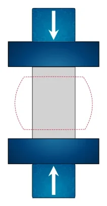
The five tests form a chain. The paper maker controls RCT and CMT, because they show how much the liner and the medium will contribute. The board maker controls ECT and FCT. The packaging user wants to know the BCT, which depends on the ECT of the board and on the box geometry. The diagram below shows the five tests side by side, with the specimen between the platens and the direction of the force. In the ECT the strip stands upright with the flutes vertical. In the FCT the board lies flat and the force tries to flatten the flutes. In the RCT the paper strip forms a ring held in a fixture. In the CMT the fluted medium is taped to a strip. In the BCT the whole box goes into the machine.
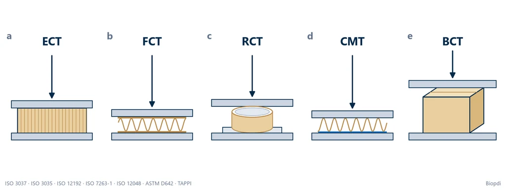
The chain works because a stacked box fails by vertical compression of its walls, with the flutes upright. That is exactly the loading in the ECT, which is why the ECT is the best predictor of the BCT. The FCT matters for a different reason. If the flutes are crushed during converting (printing, scoring, handling), the board loses caliper, and caliper also affects box strength.
Edge crush test (ECT): column strength
The edge crush test (ECT), known in Brazil as the column strength test, measures the maximum force per unit length that a strip of corrugated board withstands when compressed on its edge, with the flutes vertical. It is the most searched crush test and the one most used in specifications, because its result relates to the compressive strength of the box. It also goes by the names column crush test and edgewise crush resistance.
How the ECT is performed
Under ISO 3037:2022, the unwaxed-edge method, the procedure is as follows:
- Condition the samples according to ISO 187, and cut and test the specimens in the same atmosphere.
- Take the samples away from scores, joints and closures, free of folds, dents or machine marks. The standard points out the effect of liner waviness (washboarding).
- Cut the specimens 100.0 ± 0.5 mm long, perpendicular to the flutes, and 25.0 ± 0.5 mm high, in the flute direction. Use a high-speed saw or a parallel-blade cutter of the Billerud type. The loaded edges must be clean, straight, parallel and perpendicular to the liners.
- Stand the specimen on one of its 100 mm edges on the lower platen of a fixed-platen machine (the standard refers to ISO 13820, which sets the platen requirements). Two guide blocks, one on each side, keep it from tipping over at the start.
- Compress at 12.5 ± 0.25 mm/min and move the guide blocks away when the force reaches about 50 N.
- Record the maximum force to a resolution of 1 N, up to collapse.
- Reject any specimen that buckled (bowed into a "C") or tipped over, and test more specimens until there are 10 valid results.
Cutting quality is the largest source of error. ISO 3037 itself notes that the cutting device alone can change the result by up to 5%. ZwickRoell, a testing machine manufacturer, warns that knives and lever guillotines do not give good results. An edge crushed by the blade collapses before the rest of the strip and lowers the ECT.
Load direction in the ECT
The ECT force is vertical, with the flutes upright. It acts in the plane of the board, on the edge, along the flute axis (this is how ISO 3037 defines it). Each flute works like a small column, braced by the liners. Descriptions that say the ECT load is "perpendicular to the board" confuse the ECT with the FCT, because the load perpendicular to the board is the flat crush load. The diagram in the previous section shows the two cases side by side.
ECT formula and units
The ECT is the mean maximum force divided by the specimen length: R = F̄max / l. With force in newtons and length in millimeters, the result is in N/mm, which is the same as kN/m. ISO 3037 asks for the result to two decimal places, in kN/m. Since the length is always 100 mm, the calculation becomes ECT (kN/m) = 0.01 × F̄max (N). In the United States, ECT is given in lbf/in, and the conversion is 1 lbf/in = 4.448 N ÷ 0.0254 m = 175.1 N/m = 0.1751 kN/m (Biopdi calculation). A commercial range of 10 to 60 lbf/in therefore corresponds to 1.75 to 10.5 kN/m. Conversions that give "0.6 to 3.4 kN/m" for the same range are wrong.
The chart below shows the force vs. displacement curve of an ECT specimen, using the numbers from example 1 in this guide. The force rises almost linearly as the strip compresses, rounds off near the peak Fmax, and drops sharply when the liners buckle locally and the flutes collapse. Only the peak counts toward the result. The dotted line marks the 50 N at which the guide blocks are moved away. The part of the curve after the drop is not used in the result, as the chart below shows.
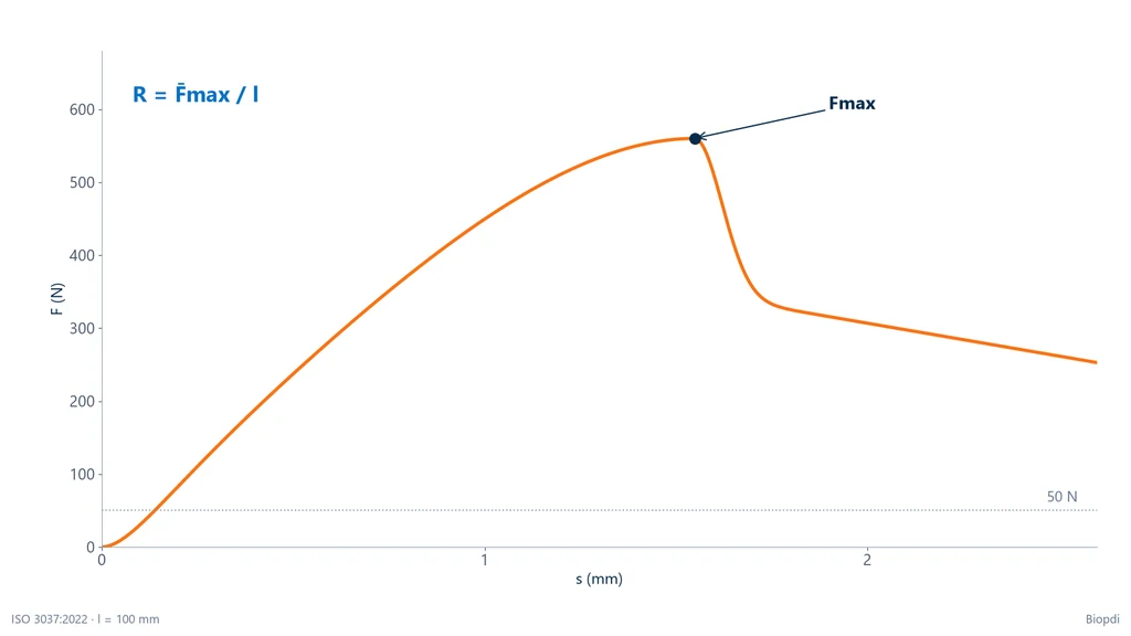
The displacement on the horizontal axis is the crosshead displacement of the machine, and it cannot be used to calculate board stiffness. Garbowski and co-workers (Materials, 2021) compared the stiffness obtained from the crosshead with the stiffness measured by digital image correlation on the specimen itself. The crosshead underestimated it by almost three times, because deformation of the platens, seating and edges all ends up in the crosshead displacement. The same study measured an ECT of 7.6 N/mm on a commercial board, consistent with the manufacturer's value. To get the stiffness, measure strain on the specimen, not at the machine.
What 32 ECT and 44 ECT mean
"32 ECT" means the board has an ECT of at least 32 lbf/in, or 5.60 kN/m. It does not mean the box holds 32 pounds. The number comes from the US motor freight packaging classification rule, Rule 41 (NMFC Item 222). The stamp printed on the box flap under this rule is the Box Maker's Certificate (BMC). For each ECT grade, the rule sets the maximum gross weight of the package and the maximum sum of outside dimensions (length + width + height). The table below lists the single-wall grades as reproduced by box manufacturers (Crown Packaging, 2023), with SI conversion by Biopdi:
| Grade (lbf/in) | Minimum ECT (kN/m) | Maximum gross weight | Maximum L + W + H |
|---|---|---|---|
| 23 ECT | 4.03 | 20 lb (9.1 kg) | 40 in (102 cm) |
| 26 ECT | 4.55 | 35 lb (15.9 kg) | 50 in (127 cm) |
| 29 ECT | 5.08 | 50 lb (22.7 kg) | 60 in (152 cm) |
| 32 ECT | 5.60 | 65 lb (29.5 kg) | 75 in (191 cm) |
| 40 ECT | 7.01 | 80 lb (36.3 kg) | 85 in (216 cm) |
| 44 ECT | 7.71 | 95 lb (43.1 kg) | 95 in (241 cm) |
| 55 ECT | 9.63 | 120 lb (54.4 kg) | 105 in (267 cm) |
For double wall, the same table runs from 42 ECT (80 lb) to 82 ECT (180 lb). For triple wall, it runs from 67 to 112 ECT (240 to 300 lb). Box retailers publish a different table of "maximum recommended load", which lists 32 ECT at 40 lb and 44 ECT at 65 lb. Both readings coexist: the BMC value is a shipping limit for the package, and the retail value is a conservative recommendation for the contents. Neither tells you how much a box holds when stacked. That depends on the box dimensions and is either estimated with the McKee formula or measured in the BCT.
ECT or Mullen (burst) test
Before the ECT, the US classification used the Mullen burst test. A rubber diaphragm presses on the board until it bursts, and the result is a pressure in kPa or lbf/in², written with the "#" sign (200# is 200 lbf/in²). The standards are ISO 2759 for board and TAPPI T 810. The Mullen test measures the board's resistance to puncturing and tearing under pressure. It is not a crush test and does not predict stacking performance. That is why the industry moved to the ECT, which measures the property the box relies on in a stack.
The usual market equivalents are 32 ECT for 200# and 44 ECT for 275#, single wall (Crown Packaging, The Boxery). The switch saves material: according to The Boxery, a 44 ECT board weighs 149 lb per 1,000 ft², against 175 lb for 275#, about 15% less paper for the same range of use. According to Safe Load Testing, UPS and FedEx accept 200# or 32 ECT for packages up to 30 lb (13.6 kg).
ECT methods that cannot be compared
There are four families of ECT methods, and the introduction to ISO 3037 warns that their results do not correlate. The first cuts a rectangle and tests it with no treatment at all; this is ISO 3037. The second dips the loaded edges in paraffin wax to keep them from collapsing before the rest of the specimen: ISO 13821:2020 and TAPPI T 811. The third narrows the specimen at mid-height to force failure away from the edges (JIS Z 0403-2). The fourth clamps the edges in grips: TAPPI T 839. ISO 3037 gives lower values than most of the others because of the edge effect. It was chosen as the quality method because it is the simplest and because it correlates with box compression.
In practice, an ECT can only be compared with another ECT from the same method. Any formula used to predict the BCT must also have been fitted with ECT values from that same method. A specification that says "minimum ECT of 7 kN/m" without naming the standard is incomplete.
Flat crush test (FCT): flat crush
The flat crush test (FCT) measures how well the flutes of corrugated board resist being flattened by a force perpendicular to the board surface. It evaluates the quality of the medium and of the flute formation. A low FCT points to poorly formed flutes or a weak corrugating medium, and it predicts caliper loss during printing and converting. ISO 3035:2025 applies to single-face and single-wall corrugated board. It does not apply to double-wall or micro-flute board, because with two flutes in series there is no way to know which one gave way first.
FCT formula
The FCT is the maximum force divided by the specimen area: FCT = Fmax / A, in kPa. With the usual 100 cm² (0.01 m²) specimen, the calculation becomes FCT (kPa) = Fmax (N) ÷ 10. A disc 112.8 mm in diameter has an area of π × 56.4² ≈ 9,993 mm², practically 100 cm², which is why circular FCT cutters have this size (Mecatécnica; Biopdi calculation). A 50 cm² specimen is also used. In US units, 1 psi = 6.895 kPa.
A common mistake on manufacturer pages is to give the FCT in kN/m. The FCT is force per area, so the unit is kN/m², which is the kPa; kN/m is the unit of the ECT. According to ZwickRoell, lower flutes give a higher FCT (there are more flutes per area and each one is shorter), micro-flutes can exceed 10 kN on the 100 cm² specimen, and a 5 kN machine covers grades of up to 500 kPa.
A curve with several peaks
The FCT curve does not have a single peak. The flutes of a real board are not all the same height: the tallest ones touch the platen first, give way, and the force drops slightly before the next ones take up the load. The result is a sequence of peaks and valleys, as described by ZwickRoell, and the test value is the collapse defined by the standard, not the highest peak after the flutes have already been flattened. This collapse pattern, with the flutes giving way in sequence, is also what you see when you inspect the specimen after the test, and it is what numerical models of corrugated board try to reproduce.
Rigid support and flexible beam
TAPPI has two FCT methods. T 825 compresses the specimen between rigid platens, like ISO 3035. T 808 uses a flexible beam in place of one of the platens, a classic method that gives significantly lower values than T 825. The two results are not comparable, and the specification must state which method applies.
Ring crush test (RCT) and CMT: paper tests
RCT and CMT are the crush tests for paper, carried out before it is converted into corrugated board: the RCT measures the edgewise compression strength of the liner or medium, and the CMT measures how well the already fluted medium resists flattening. These are the tests that let the papermaker predict the ECT and FCT of the board that will be produced.
Ring crush test (RCT)
In the ring crush test, a narrow strip of paper or paperboard (12.7 mm wide, according to ZwickRoell) is curled into a ring and fitted into a holder with a circular groove, so that only one edge is exposed. The upper platen compresses the ring edgewise until it collapses. The ring shape solves a problem: a straight strip of paper standing on edge would buckle before crushing; curled, it gains stability. The result is the maximum force, or that force divided by the strip length, with the machine direction and the cross direction of the paper tested separately.
ISO 12192:2011 applies to paper and paperboard from 100 µm to 580 µm thick and warns that below 280 µm the result mixes buckling and compression. TAPPI T 822 om-22 was developed for thicknesses from 0.28 to 0.61 mm. For thinner paper, the short-span compression test (SCT, ISO 9895 and TAPPI T 826) measures pure compression over a span of a few millimeters and is the alternative.
CMT (Concora medium test)
In the CMT, a strip of corrugating medium is fluted in the laboratory, in a corrugator with heated rolls, stuck to an adhesive tape to hold the flute pitch, and compressed flat, like an FCT without liners. The result is the maximum force, in N. ISO 7263-1:2018 covers A flute, and ISO 7263-2 covers B flute; TAPPI T 809 om-22 presents the CMT as an estimate of the FCT the medium will give in the board.
Box compression test (BCT) and the McKee formula
The BCT (box compression test) compresses the whole box between two platens until it collapses and measures the maximum load it withstands, in N or lbf; it is the test that tells you how much weight the box can take. The standards are ASTM D642-25, ISO 12048:1994, TAPPI T 804 and, in Brazil, ABNT NBR 6739 (the Brazilian standard for box compression testing). The box can be tested empty, erected and closed as it will be shipped, or filled, and the load can be applied to the faces, edges or corners, according to D642.
How the box compression test is done
The conditioned box is placed between two platens larger than the box, and the machine closes the platens at constant speed until the force passes through a maximum. In the photo, a closed corrugated box is being compressed between the steel platens: the side panel has bulged and the first buckling crease has appeared near the corner. This is the typical BCT pattern, because the corners are the stiffest regions of the box and concentrate the load; the panel between them buckles outward, and collapse starts where the panel meets the corner.
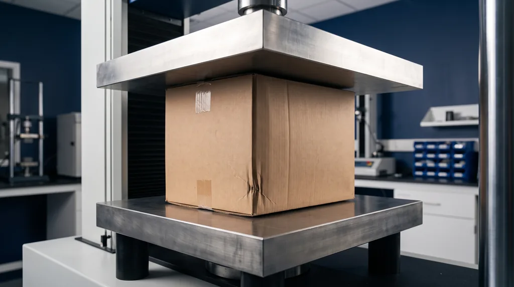
The type of platen changes the result. ASTM D642 notes that fixed platens, parallel and locked, tend to fail the box at its strongest point, while a floating (swiveling) platen, which can tilt, fails it at its weakest point. The report must state which one was used. ISO 12048 also covers the stacking test: the filled box is kept under a constant load for a period of time, which measures creep and not just the peak.
McKee formula
The McKee formula estimates the BCT of a box from the ECT of the board, the board caliper and the box perimeter: BCT = 5.87 × ECT × √(h × Z). In it, h is the board caliper and Z is the box perimeter, Z = 2 (C + L), with C the length and L the width. The constant 5.87 is dimensionless (Wikipedia gives it with one more decimal place, 5.876), so the formula works in any consistent system: ECT in lbf/in with h and Z in inches gives BCT in lbf; ECT in N/mm with h and Z in millimeters gives BCT in N. It is the simplified form of the equation published by McKee, Gander and Wachuta in 1963 (Paperboard Packaging, v. 48, no. 8), which in its full form uses the flexural stiffness of the board.
The diagram below shows the quantities of the formula on an RSC box (regular slotted container, the common box with flaps), with the numbers from example 4: the perimeter Z in blue at the base, the caliper h in the board detail and the result of 555 lbf (2.47 kN) for a 16 × 12 in box made of 32 ECT C-flute board. The height A does not enter the simplified form.
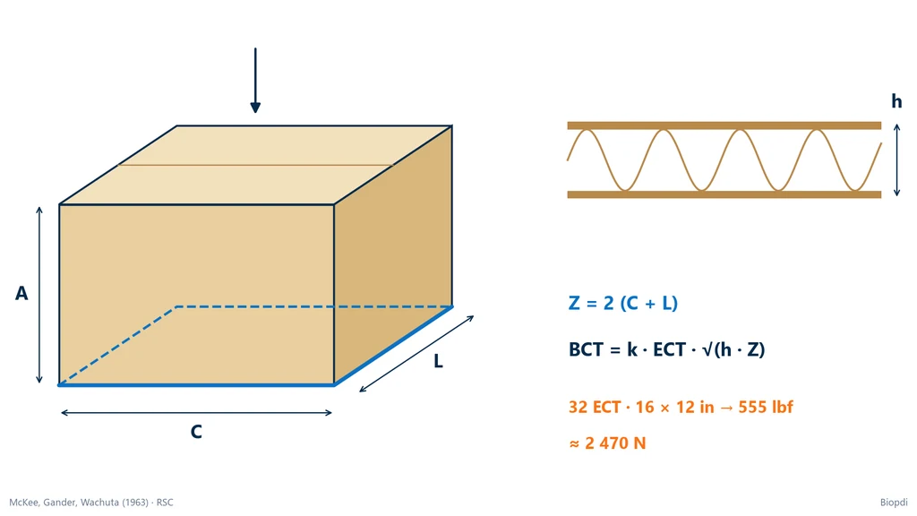
The formula has clear limits. It applies to RSC boxes with vertical flutes, in usual proportions; it does not account for holes, handles, heavy printing, misaligned flaps or misplaced scores. As Westpak, a packaging testing laboratory, points out, the estimate does not replace the BCT measured on a conditioned box, and the BCT is not the allowable stacking load: it is the collapse load in a fast test, in a standard atmosphere.
From compression to the stack: humidity, time and pattern
A box stacked in a warehouse stays under load for weeks, in varying humidity, often misaligned on the pallet. Each of these factors reduces the load it can take compared with the laboratory BCT:
- Humidity: paper absorbs water and loses stiffness. This is the factor with the greatest weight.
- Time under load: corrugated board creeps and can collapse under a constant load lower than the BCT, after days or weeks.
- Stacking pattern: boxes stacked in columns, corner on corner, take advantage of the corner stiffness; boxes stacked interlocked (offset) lose part of it. Flaps overhanging the pallet edge and gaps between the deck boards also reduce capacity.
- Holes and handles: they remove material from precisely the panels that carry the stack.
The chart below shows the effect of relative humidity (φ) on the ECT of a B-flute board, as a percentage of the reference value of 4.51 kN/m (Mrówczyński et al., Applied Sciences, 2024). At 20 °C, the ECT stays close to the reference value up to 70%, drops to 76% at 80% humidity and to 45% at 90%; at 10 °C and 90%, it reaches 41%. In the same study, with six different boards, the minimum ECT ranged from 22% to 41% of the reference value, depending on the flute; the chart below shows only the B flute.
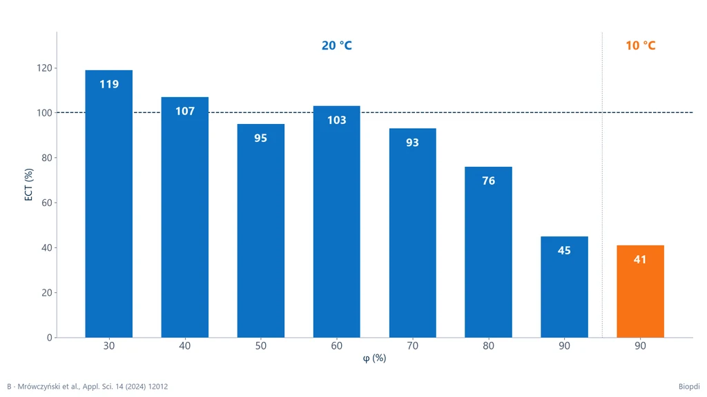
That is why the market applies a safety factor to the BCT or to the McKee estimate. Box manufacturers cite factors from 3:1 to 5:1 depending on storage time and humidity, and losses of 30% to 50% of the BCT at high humidity (President Container Group). These are industry practices, not requirements of a standard; anyone with a critical case measures the BCT and runs the stacking test under real conditions.
Worked examples of the crush test
The examples below are illustrative, with numbers consistent with the published ranges, and the calculations are by Biopdi. The conversions use 1 lbf = 4.448 N, 1 in = 25.4 mm and 1 lbf/in = 0.1751 kN/m.
1. ECT of a single-wall lot (ISO 3037). Ten valid 100 mm specimens, conditioned at 23 °C and 50% relative humidity and tested at 12.5 mm/min, gave a mean maximum force F̄max = 560 N. ECT = 560 N ÷ 100 mm = 5.60 kN/m. In US units: 5.60 ÷ 0.1751 = 32.0 lbf/in. The board meets the 32 ECT grade, at the limit. If one of the specimens had buckled, it would be discarded and replaced, and would not enter the mean.
2. What a 44 ECT board needs to reach on the machine. 44 lbf/in × 0.1751 = 7.71 kN/m. On the 100 mm specimen, the minimum mean maximum force is 7.71 N/mm × 100 mm = 771 N. This is the number the laboratory compares with the mean of the ten specimens.
3. FCT of a C flute. A 100 cm² (0.01 m²) specimen collapsed at 2,500 N. FCT = 2,500 N ÷ 0.01 m² = 250,000 Pa = 250 kPa (36.3 psi). With the quick calculation, 2,500 ÷ 10 = 250 kPa. The value is illustrative: there is no peer-reviewed source of typical FCT by flute type, and each manufacturer specifies its own.
4. McKee on an RSC box. A 16 × 12 in (406 × 305 mm) box, 32 ECT C-flute board with caliper h = 0.156 in (3.96 mm, catalog value; on the real box, measure it). Perimeter: Z = 2 × (16 + 12) = 56 in. Square root: √(0.156 × 56) = √8.736 = 2.956 in. BCT = 5.87 × 32 × 2.956 = 555 lbf. In SI: ECT = 5.604 N/mm, Z = 1,422.4 mm, √(3.962 × 1,422.4) = 75.07 mm, BCT = 5.87 × 5.604 × 75.07 ≈ 2,470 N (2.47 kN), the same as 555 × 4.448. Checking in both systems shows that the constant is dimensionless.
5. From the estimate to the stack. The same box, filled, weighs 13 kg, or 13 × 9.807 = 127.5 N. In the standard atmosphere and without a safety factor, 2,470 ÷ 127.5 = 19.4: the bottom box would support 19 boxes on top of it (a stack of 20). Using as an illustration the retention of B-flute board at 10 °C and 90% humidity (41% of the reference ECT) and assuming the BCT is proportional to the ECT, as in the McKee formula: 2,470 × 0.41 = 1,013 N, and 1,013 ÷ 127.5 = 7.9, that is, 7 boxes on top of the bottom one (a stack of 8). With a 3:1 safety factor in the standard atmosphere: 2,470 ÷ 3 = 823 N, and 823 ÷ 127.5 = 6.5, or 6 boxes on top of the bottom one (a stack of 7). Creep and the stacking pattern reduce these numbers even further, which is why the final decision comes from testing.
Conditioning and common mistakes
Every crush test on paper and corrugated board starts with conditioning in the standard atmosphere of ISO 187:2022, 23 °C and 50% relative humidity, with 27 °C and 65% allowed in tropical countries. The same standard recommends reaching equilibrium from a lower humidity, because paper has hysteresis: the equilibrium moisture content depends on whether the paper dried out or took up moisture to get there. As the humidity chart showed, a few points of humidity change the ECT measurably; results from laboratories that condition in different ways are not comparable.
The mistakes that most distort the result, or how it is read:
- Not conditioning, or conditioning in one atmosphere and testing in another.
- Cutting the ECT specimen poorly, with a knife or a lever guillotine: a crushed edge collapses early and lowers the result.
- Using a different speed without recording it: ISO 3037 calls for 12.5 mm/min, and 10 mm/min, common in some regions, changes the value.
- Accepting a specimen that buckled or tipped over in the ECT, instead of discarding and replacing it.
- Comparing ECT from different methods (unwaxed, waxed edges, clamped) or using a BCT formula fitted with another method.
- Running FCT on double-wall board, outside the scope of ISO 3035.
- Comparing FCT from rigid support and flexible beam (TAPPI T 825 and T 808).
- Mixing up units: ECT is force per length (kN/m), FCT is force per area (kPa), Mullen is pressure (kPa or lbf/in²); "200#" does not mean the box holds 200 lb, and "32 ECT" does not mean 32 lb.
- Ignoring the platen type in the BCT: fixed and floating platens give different results.
- Applying McKee outside its domain (a box that is not an RSC, with holes or handles) or treating the result as a stacking load.
- Citing the wrong standard: ECT is ISO 3037, FCT is ISO 3035, RCT is ISO 12192 and CMT is ISO 7263. Texts that swap these numbers, or that cite an "ISO 14260" (which does not exist), lead to wrong purchases and specifications.
The table summarizes the control points for each test:
| Test | Critical point | Consequence |
|---|---|---|
| All | conditioning per ISO 187 | high humidity drives the result down |
| ECT | cutting, speed, buckling | a poor edge and tipping lower the ECT |
| FCT | scope and support method | double-wall and flexible beam are not comparable |
| RCT | paper thickness | below 280 µm, buckling enters the result |
| BCT | platen type, creep | a floating platen finds the weak point; the stack gives way below the BCT |
Other crush tests: pipes, honeycomb cores and batteries
Outside packaging, the name "crush test" also covers tests on pipes, on sandwich panel cores, and the safety tests for transport packages and batteries, each with its own standard. The principle is the same in all of them: a compressive force is applied to the whole part, either up to a defined deformation or until it collapses.
- Plastic pipe between parallel plates: ASTM D2412-21 compresses a section of thermoplastic or reinforced resin pipe between two plates and determines the pipe stiffness and the load at specified deflections.
- Concrete pipe: ASTM C497/C497M-25 covers crushing strength under external load in the three-edge bearing test. In Brazil, concrete pipes follow ABNT NBR 8890.
- Honeycomb cores and foams for sandwich panels: ASTM C365/C365M-22 compresses the core perpendicular to the facings (flatwise), a common test in the aerospace industry. Shear of the same core follows ASTM C273, covered in the article on the shear test.
- Transport packages for radioactive material: the transport regulations include a crush test in which a plate is dropped onto the package. National laboratories such as Oak Ridge National Laboratory in the United States have facilities for these tests.
- Lithium cells and batteries: section 38.3 of the UN Manual of Tests and Criteria includes an impact and crush test on cells for transport.
Axial compression of solid parts such as columns, blocks and concrete specimens is a compression test, not a crush test, and is covered in the article on the compression test.
Crush testing machine: crush tester or universal testing machine
A crush test needs a compression machine with flat, parallel platens, a constant speed and a load cell sized for the test force. This can be a dedicated crush tester or a universal testing machine (UTM) fitted with compression platens. A crush tester is a compact machine with guided platens, built for ECT, FCT, RCT and CMT, with a force range of a few kilonewtons. A universal testing machine runs the same tests with the fixtures each standard calls for. With platens larger than the box, it also runs BCT, and it handles the lab's other tests as well, such as tensile tests on paper and films. ZwickRoell, for example, runs ECT, RCT, FCT and CMT on a single-column universal testing machine with one set of fixtures.
The forces involved determine the choice of load cell. The table below uses the figures from this guide (Biopdi calculation):
| Case | Calculation | Maximum force |
|---|---|---|
| ECT of 32 lbf/in over 100 mm | 5.60 kN/m × 0.1 m | 560 N |
| ECT of 112 lbf/in (triple wall) over 100 mm | 19.6 kN/m × 0.1 m | 1.96 kN |
| FCT of 250 kPa over 100 cm² | 250 kPa × 0.01 m² | 2.5 kN |
| BCT of the box in example 4 | McKee | 2.47 kN |
The fixtures are what change from one test to another. ISO 3037 calls for a fixed-platen machine as specified in ISO 13820, which sets the flatness and parallelism of the platens, plus guide blocks for ECT. RCT needs the holder with a circular groove, FCT a 100 cm² cutter, CMT the laboratory fluter, and BCT platens larger than the box. Each standard defines its own fixtures, so check them against that standard before testing.
Crush testing on the Biopdi universal testing machine
The Biopdi universal testing machine runs compression tests with 1 kN, 50 kN and 300 kN compression platens. ABNT NBR 6739, the Brazilian standard for compression testing of corrugated board packaging, is one of the standards listed on the machine's page. For corrugated board testing, Biopdi supplies ECT, RCT and FCT fixtures for the universal testing machine: ECT guide blocks, an RCT ring holder and a flat FCT crush platen. The setup for each customer's standard is agreed with the Biopdi technical team. The panel below shows the machine, what each part does in a crush test, and the compression platens.
The universal testing machine in a crush test
The M2 line has single-column models from 200 N to 10 kN and dual-column models from 5 kN to 1,000 kN. Each part of the machine has a role in the test:
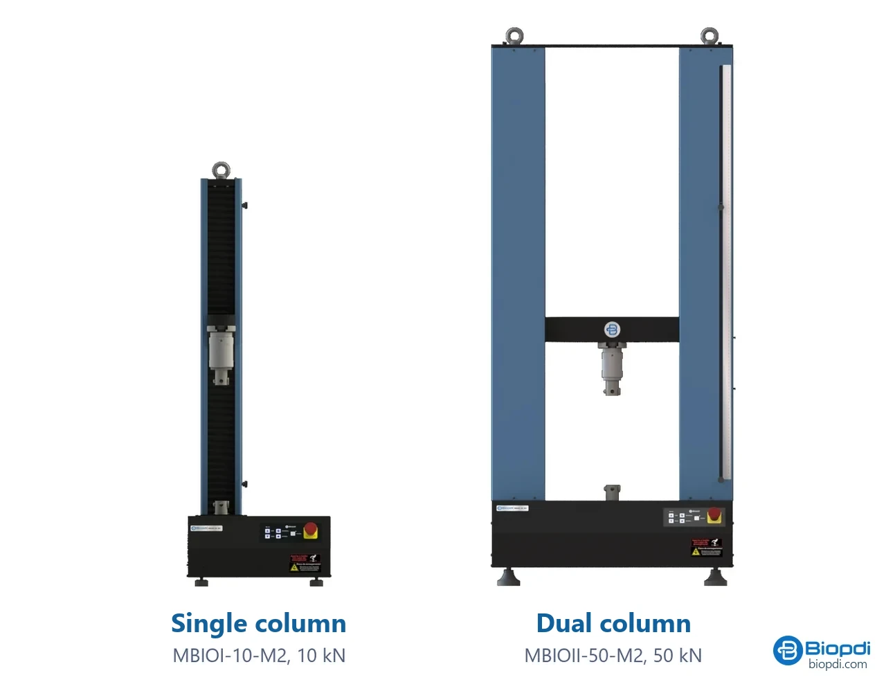
- Moving crosshead brings the platens together at the speed set by the standard
- Load cell sized for the maximum test force
- Compression platens flat and parallel, fitted in place of the grips
- Displacement measured from the crosshead, no extensometer needed
- BioLab software records the curve, maximum force and maximum position
- Control panel and emergency stop to position the crosshead and stop the test
Fixtures for crush testing
The compression platens are mounted on the same universal testing machine, in place of the tensile grips. For ECT, RCT and FCT, Biopdi supplies guide blocks, a ring holder and a flat crush platen:
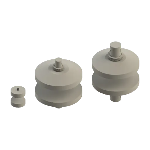
The rule for choosing a model is to size the load cell for the expected force, then check the test space and the stroke against the specimen size. Paper and board tests stay below a few kilonewtons. The portable machine, rated 200 N to 1 kN, lists "films, paper, wires, tapes and small components" among the applications on its datasheet. Box tests need a test space and platens that fit the box. Every model in the table reaches the 12.5 mm/min ECT speed. The BioLab software, in its tension and compression configuration, records the curve and calculates maximum force and maximum position. Dividing by the length (ECT) or the area (FCT) is the calculation shown in the examples. To compare models and configurations, see how to choose a universal testing machine.
| Application | Range | Biopdi model |
|---|---|---|
| Paper, films, tapes and small components | 200 N to 1 kN; 0.01 to 600 mm/min | MBIOI-1P-M2 portable |
| Corrugated board sheets, polymers, foams | 2 to 10 kN; 0.01 to 500 mm/min; 150 mm test space | MBIOI-10-M2 |
| Larger parts, metals, composites | 5 to 50 kN; 0.01 to 500 mm/min; 425 mm test space | MBIOII-50-M2 |
The crush test is one of the many mechanical tests the same universal testing machine can run. Force accuracy depends on the calibration of the measuring system, covered in the article on universal testing machine calibration to ISO 7500-1 (ABNT NBR ISO 7500-1 in Brazil). Choosing the measuring range is covered in the article on the load cell.
Crush test standards
The crush test standards for corrugated board are ISO 3037 (ECT), ISO 3035 (FCT), ISO 12192 (RCT), ISO 7263 (CMT), and ISO 12048 and ASTM D642 (BCT), with their TAPPI and ABNT (Brazilian) counterparts. We checked the edition and status of each standard in the table against the ISO catalog, the ASTM store and the TAPPI catalog on October 13, 2026. The ABNT standards are listed without an edition because their current edition and status could not be confirmed in the ABNT catalog as of the date of this guide.
| Standard and edition | Test | Note |
|---|---|---|
| ISO 3037:2022 | ECT, unwaxed edge | 6th edition; replaced the 2013 edition; single, double and triple wall |
| ISO 13821:2020 | ECT, waxed edge | replaced the 2002 edition |
| TAPPI T 811 om-23 and T 839 om-24 | ECT, waxed (T 811) and clamp method (T 839) | not comparable with ISO 3037 |
| ISO 3035:2025 | FCT | 4th edition; replaced the 2011 edition; single face and single wall only |
| TAPPI T 825 om-24 and T 808 | FCT, rigid support (T 825) and flexible beam (T 808) | results differ between the two |
| ISO 12192:2011 | RCT | confirmed in 2022; 100 to 580 µm |
| TAPPI T 822 om-22 | RCT, rigid support | developed for 0.28 to 0.61 mm |
| ISO 7263-1:2018 and ISO 7263-2 | CMT, A flute (1) and B flute (2) | part 1 confirmed in 2024; replaced ISO 7263:2011 |
| TAPPI T 809 om-22 | CMT | estimates the potential FCT |
| ISO 12048:1994 | BCT and stacking of filled packages | confirmed in 2022 |
| ASTM D642-25 | BCT of shipping containers and unit loads | faces, edges or corners; fixed or swiveling platen |
| TAPPI T 804 om-24 | BCT | TAPPI box compression method |
| ISO 187:2022 | conditioning | 3rd edition; 23 °C and 50% RH; 27 °C and 65% RH in the tropics |
| ABNT NBR 6737, NBR ISO 3035, NBR ISO 12192, NBR ISO 7263 and NBR 6739 | ECT, FCT, RCT, CMT and BCT | Brazilian equivalents; check edition and status in the ABNT catalog |
Two notes on status. Older texts and supplier pages still cite ISO 3037:2013, ISO 3035:2011 and ISO 13821:2002, all of which have been superseded. The other crush test standards cited in this guide are at these editions: ASTM D2412-21, ASTM C497/C497M-25 and ASTM C365/C365M-22.
Other tests and technical references
Tests performed on the Biopdi universal testing machine







Related technical references
ASTM D790: three-point flexural test of plastics (procedures A and B, support span and calculations)
ASTM D790-25 measures the flexural strength and flexural modulus of plastics using a bar on two supports loaded at midspan. The support span is 16 times the thickness. The strain rate is 1%/min (procedure A) or 10%/min (procedure B), and the test runs until the specimen breaks or reaches 5% strain. Covers the crosshead speed R = ZL²/6d, the formulas, the large-deflection correction, a comparison with ISO 178 and D6272, and worked examples.
Flexural test: 3-point and 4-point bending, how to calculate flexural strength, and standards
In a flexural test, a bar supported at two points is loaded until it fails. Learn 3- and 4-point setups, flexural strength and modulus formulas, NBR 12142 and ASTM D790.
Axial-torsion test: combined tension and torsion, von Mises and standards
The axial-torsion test applies axial force and torque to the same specimen. See the tube stresses, von Mises, examples, ASTM E2207 and the machine.
Frequently asked questions
What is a crush test?
A crush test compresses a part between two platens until it collapses and records the maximum force. In packaging, the tests are called ECT, FCT, RCT, CMT and BCT. Other names include crushing test and column crush test. A crush test has nothing to do with a crusher, which is mining equipment.
What does 32 ECT mean?
It means the corrugated board has an ECT of at least 32 lbf/in, or 5.60 kN/m. Under the Box Maker's Certificate rule, a 32 ECT single-wall box can carry up to 65 lb (29.5 kg) gross weight, with dimensions adding up to no more than 75 in. It does not mean the box holds 32 lb.
What does 44 ECT mean?
It means the corrugated board has an ECT of at least 44 lbf/in, or 7.71 kN/m. That is an average force of 771 N on the 100 mm specimen. Under the Box Maker's Certificate rule, a 44 ECT single-wall box carries up to 95 lb (43.1 kg) gross weight. The Mullen test equivalent is 275#.
How is ECT calculated, and in what unit?
ECT = F̄max / l, the average maximum force of at least 10 specimens divided by the 100 mm length. With N and mm the result is in N/mm, which equals kN/m. In the USA it is given in lbf/in (1 lbf/in = 0.1751 kN/m). Example: 560 N ÷ 100 mm = 5.60 kN/m = 32 lbf/in.
What is the flat crush test (FCT) formula?
FCT = Fmax / A, in kPa. With a 100 cm² specimen (a disc 112.8 mm in diameter), FCT (kPa) = Fmax (N) ÷ 10. Example: 2,500 N over 100 cm² = 250 kPa. ISO 3035:2025 applies to single face and single wall board.
What is the McKee formula?
The McKee formula estimates a box's compression strength from its ECT: BCT = 5.87 × ECT × √(h × Z), where h is the board thickness and Z is the box perimeter. It applies to RSC boxes and gives the collapse load in the lab, not the allowable load in a stack. Example: 32 ECT, 16 × 12 in box, C flute: 555 lbf (2.47 kN).
What is the difference between crushing strength and compressive strength?
For brittle materials (concrete, brick, cast iron), they are the same thing: the stress at compressive failure. A ductile metal does not crush by fracture. It yields and barrels, so the value used is the compressive yield strength. In packaging, crush resistance is the maximum force the part carries, not a stress in the material.
What is the difference between ECT and the Mullen (burst) test?
ECT compresses a strip of corrugated board on its edge and measures force per unit length, which is the property a box relies on in a stack. The Mullen test presses a diaphragm against the board until it bursts and measures pressure, in kPa or lbf/in² (ISO 2759, TAPPI T 810). The equivalents used in the market are 32 ECT for 200# and 44 ECT for 275#.
What machine performs a crush test?
Either a dedicated crush tester with guided platens and a capacity of a few kilonewtons, or a universal testing machine with compression platens and the fixtures each standard requires. These fixtures include ECT guide blocks, an RCT ring holder and an FCT platen, which Biopdi supplies for its universal testing machine. A universal testing machine also runs BCT with platens larger than the box, as well as the lab's other tests.
What are the types of corrugated board?
Single face (one liner and one medium), single wall (two liners and one medium), double wall (three liners and two mediums) and triple wall. From tallest to shortest, the most common flutes are A, C, B and E. Thickness depends on the flute and the manufacturer, and is measured on the board according to ISO 3034.