
The pull-out test pulls an embedded element, such as an anchor, a steel bar, a soil nail, a screw or a fiber, until it is pulled out of the base material or until a proof load is reached. The machine records force and displacement. The peak force gives the anchorage capacity and the average bond stress, τ = F / (π·d·ℓ). For anchors, the standards are ABNT NBR 14827 (the Brazilian standard for anchor pull-out testing) and ASTM E488. For soil nails, NBR 16920-2 (the Brazilian soil nailing standard) applies. For ground anchors, NBR 5629 (the Brazilian ground anchor standard) applies.
This test tells you whether a fastening can carry the load the design calls for. Examples include the anchor that holds down a machine, the anchorage point of a lifeline, the nail in a retaining structure, and the screw in a piece of furniture or an orthopedic plate. This guide explains where the strength of a fastening comes from and how the test is done in the field and in the laboratory. It also covers the failure modes, the formulas with worked examples, the most common mistakes and the standards for each application.
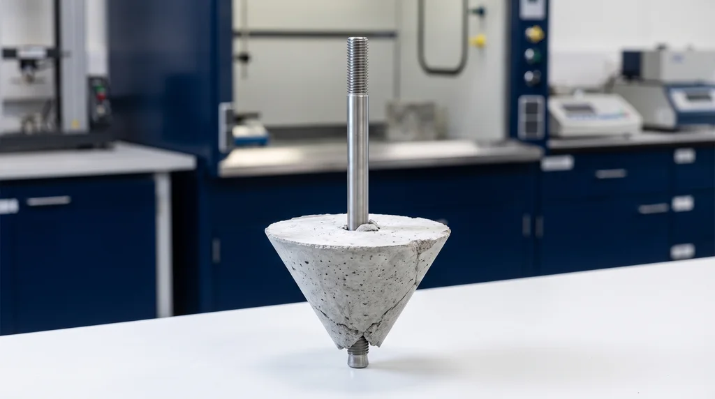
The photo shows a steel anchor pulled out of concrete. It did not come out alone. A cone of concrete is attached to its tip, wide at the face that was the block surface and narrow at the embedded end. This is the most common failure mode for shallow anchors, and it explains many of the rules of the test.
What is the pull-out test
The tested element is embedded in a base material, which can be concrete, masonry, soil, wood, bone or the matrix of a composite. The length of the element inside that material is the embedment depth (for bars and soil nails, the bonded length). It is the variable with the greatest effect on the result. When the element is pulled along its axis, its resistance comes from four mechanisms, alone or combined:
- Bond: the connection between the surface of the element and the material around it. Examples are the concrete around a bar, the resin of a chemical anchor and the cement grout of a soil nail.
- Friction: the element pressing against the wall of the hole, as in a mechanical expansion anchor.
- Mechanical interlock: the ribs of a bar or the threads of a screw bearing on the base material.
- Breakout cone: in anchors, tension spreads through the concrete around the tip. If the concrete fails before the steel, a whole cone of material comes out, like the one in the photo.
The main result is the pull-out force, the highest force the fastening withstood. Dividing it by the lateral contact area between the element and the base material gives the average bond stress. The full force vs. displacement curve also shows how much the fastening moves under service load and how it fails.
These results have three uses. The first is product qualification, for example of an anchor or a screw, using test series taken to failure. The second is checking on site that a fastening was installed correctly. The third is research on materials and anchoring systems, such as resins, thread geometries and fibers.
Pull-out is not the same as pull-off (coating adhesion). In a pull-off test, a metal dolly is glued to a mortar, tile or paint layer and pulled perpendicular to the surface to measure the adhesion of that layer (ABNT NBR 13528). In a pull-out test, the part that comes out is an embedded element. Search results often mix the two. Pull-off testing is explained in bond test.
Where the pull-out test is used
The principle is the same for very different elements, but each one has its own standard and test location. Anchors are tested both in the laboratory and on site. Ground anchors, soil nails and piles are tested in the ground where they will work. Bars, fibers and small fasteners, such as wood screws and bone screws, are tested in the laboratory. The table lists the element, location and standard for each case:
| Element | Where | Standard |
|---|---|---|
| Mechanical and chemical anchors in concrete and masonry | laboratory and site | ABNT NBR 14827, ASTM E488/E488M-22, EAD 330232, ACI 355.2 and 355.4 |
| Ground anchors (tiebacks) | site (qualification and acceptance) | ABNT NBR 5629:2018 |
| Soil nails in soil nailing walls | site | ABNT NBR 16920-2:2021 |
| Solar plant piles (pull out test) | site | project-specific |
| Anchorage devices for work at height | laboratory (type test) and design | ABNT NBR 16325-1 and -2, NR-35 (the Brazilian regulation on work at height) |
| Steel bars in concrete (bond) | laboratory | RILEM RC6 |
| Nails, staples and screws in wood | laboratory | ASTM D1761-20 |
| Bone screws (orthopedics) | laboratory | ASTM F543-23, Annex A3 |
| Fibers in a matrix (fiber-reinforced concrete, composites) | laboratory | research methods |
| Threaded inserts in plastic | laboratory | in-house method (no specific standard) |
How the pull-out test is performed
In any setting, the test means holding the base material in place, pulling the element along its axis and measuring force and displacement. The equipment and the goal are what change. On site, the test checks the real fastening as installed. In the laboratory, it qualifies products and records the full curve to failure at a controlled rate.
On site
On site, a hollow (center-hole) hydraulic jack pulls the element. The jack is connected to a pump with a calibrated pressure gauge, and a dial indicator or extensometer reads the displacement of the head. Load is applied in stages. The jack support must sit away from the element, more than 1.5 times the embedment depth. If it is closer, it compresses the concrete exactly where the breakout cone would form, stops the cone from separating and overestimates the capacity. For soil nails, the failure criterion is continuous displacement with no increase in load, and the report includes load vs. displacement and displacement vs. time plots. For ground anchors, NBR 5629 separates qualification tests from acceptance tests. Acceptance tests are run on every anchor: type A on 10% of them and type B on the rest.
A proof load test of anchors on site checks the installation, not the ultimate capacity. A load above the service load is applied (for example, 1.5 times the applied load, as in the British standard BS 8539), and the test confirms that there is no noticeable movement.
In the laboratory
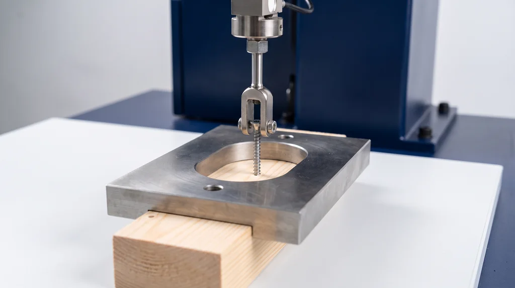
In the laboratory, the specimen is clamped to the base of a universal testing machine. The specimen can be a concrete block with a bar or anchor, a wood block with a screw, a foam block with a bone screw, or a matrix with a fiber. The crosshead pulls the element through a pull-out fixture. The load cell measures the force. Displacement comes from the crosshead or, more accurately, from a transducer on the element itself. This setup records the full force vs. displacement curve to failure at a controlled rate, and it is the standard approach for product qualification and research.
The photo below shows a screw pull-out test in wood. A steel plate holds the block against the base, with a wide opening around the screw so that it does not bear on the region that will be pulled out. A fork connected to the load cell hooks under the screw head.
What affects the result
Apart from the geometry of the fastening, three factors change the measured force. They must be controlled and recorded in the report:
- Installation: the specimen must be assembled as the manufacturer or the design specifies. In a chemical anchor, dust left in the hole weakens the resin bond, and the resin must fully cure before the test. In a mechanical anchor, the tightening torque sets the expansion. With a poor installation, the test measures the assembly error instead of the product.
- Loading rate: the failure force depends on how fast the load is applied, especially when resin, polymer or wood is in the load path. For this reason the standard or the design sets the rate, and it is recorded in the report.
- Temperature and moisture: chemical anchor resins lose strength at high temperature, and the strength of wood changes with its moisture content. Both are measured and recorded. When the test compares products, both are kept the same for all of them.
Failure modes of an anchor in tension
An anchor in tension can fail in five ways. The mode depends on which part gives way first: the steel rod, the anchorage in the hole or the surrounding concrete.
- Steel failure: the rod breaks. This happens when there is more than enough embedment and concrete.
- Pull-out or slip: the anchor slides out of the hole without taking concrete with it.
- Concrete cone: a concrete cone comes out, with a radius of about 1.5 times the embedment depth. This is the most typical mode for shallow anchors.
- Splitting: the concrete cracks, near edges or in thin members.
- Bond (chemical anchor): a combined failure of the resin together with a shallow cone.
Identifying the failure mode is part of the result, because each mode points to a different cause. The force vs. displacement curve gives the first clue. Pure slip drops gradually to a friction plateau. Cone and splitting failures drop suddenly. Steel failure shows yielding and then fracture of the rod. After the test, examining what came out confirms the reading: the shape and size of the cone, the splitting crack, or resin stuck to the rod or the hole. The observed mode goes in the report along with the peak force.
Pull-out of steel bars from concrete
Steel-to-concrete bond is measured with the classic RILEM pull-out test (RC6), which is now a historical reference. A bar is cast in a cube with a short bonded length of 5 diameters and pulled while the slip at the free end is measured. In a ribbed bar that fails by pull-out, the peak coincides with crushing of the concrete between the ribs. Watch out for a common mix-up: ABNT NBR 7477, cited in Brazilian rebar specifications, determines the bond (surface geometry) coefficient with a cracking test on concrete tension members, not with a pull-out test. Tensile testing of the bar itself is covered in tensile test.
Pull-out of screws from wood and bone
Wood (ASTM D1761-20). The nail, staple or screw is pulled at a constant rate until it comes out, and the maximum load is recorded. According to the Wood Handbook from the U.S. Forest Service, the withdrawal resistance of a wood screw increases with the square of the wood density. Within limits, it is also proportional to the penetrated thread depth and to the diameter.
Bone screws (ASTM F543-23). In Annex A3, the screw is inserted at 3 rpm into a block of standardized rigid polyurethane foam (ASTM F1839) and pulled out at 5 mm/min. This test is required for regulatory approval of orthopedic implants. The foam replaces bone so that the results are reproducible.
How to calculate: bond stress and capacity
All the calculations start from the measured peak force. Bars and soil nails resist along their whole embedded length, so the force is divided by the lateral contact area, π × diameter × bonded length. The result is the average bond stress, τ, in MPa. For a soil nail, the diameter used is that of the hole, which is filled with grout. The result, called qs, is the strength of the soil-nail interface, given in kPa.
For an anchor that fails by concrete cone, capacity does not depend on the contact area. It depends on the volume of concrete that breaks away. It is calculated with an empirical formula that increases with the square root of the concrete strength and with the effective embedment depth, hef, raised to the power 1.5. The coefficient k1 is lower for cracked concrete. ACI 318-25 uses the same form, with the coefficient kc and the cylinder strength f'c.
Two corrections complete the calculation. Results within a test series vary, so the design value is not the mean but the characteristic resistance: the mean minus a statistical factor times the standard deviation. In the field, the displacement read at the head of a ground anchor or soil nail also includes the elastic elongation of the free length of the bar. That elongation is calculated with Hooke's law and subtracted before the anchorage slip is evaluated.
The table summarizes the formulas:
| Quantity | Formula | Note |
|---|---|---|
| Average bond stress (embedded bar) | τ = F / (π·d·ℓb) | d is the diameter and ℓb the bonded length |
| Soil-nail interface strength | qs = Fmax / (π·D·Lb) | D is the hole diameter and Lb the grouted length; in kPa |
| Concrete cone, single anchor | N⁰Rk,c = k1·√fck,cube·hef1.5 | k1 = 10.1 uncracked; 7.2 cracked (ABECE, 2022) |
| Concrete cone, ACI 318-25 | Nb = kc·√f'c·hef1.5 | kc = 10 cast-in; 7 post-installed |
| Characteristic resistance of a series | Rk = Rm − kn·s | mean minus a statistical factor times the standard deviation |
| Elastic elongation of the free bar (field) | δ = F·Lfree / (E·A) | subtract from the displacement measured at the head |
The calculated bond stress is an average. It works well for short lengths, such as the 5 diameters of the RILEM test. In long anchorages, the actual stress concentrates at the start of the bonded length. For reinforcement design, NBR 6118 (the Brazilian code for the design of concrete structures) uses the design bond strength fbd = η1·η2·η3·fctd, with η1 = 1.0 for plain bars, 1.4 for indented bars and 2.25 for ribbed bars.
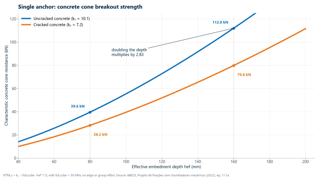
The chart below applies the cone formula to a single anchor in 30 MPa concrete, as a function of embedment depth. Capacity grows with hef raised to the power 1.5, so doubling the depth from 80 to 160 mm multiplies the capacity by 2.83. The cracked concrete curve stays about 29% below the uncracked curve across the whole range, which is the ratio between the coefficients 7.2 and 10.1.
Solved pull-out test examples
1. Bond stress of a bar. A 10 mm ribbed bar, cast with a bonded length of 50 mm (5 diameters), pulled out at 18.0 kN. The lateral area is π × 10 × 50 = 1,570.8 mm², and τ = 18,000 / 1,570.8 = 11.5 MPa.
2. Concrete cone. A single anchor, with no edge effects, at an effective embedment depth of 80 mm in 30 MPa concrete (cube strength). Uncracked: 10.1 × √30 × 801.5 = 39.6 kN. Cracked: 7.2 × √30 × 801.5 = 28.2 kN. These are the two points marked at 80 mm in the chart above.
3. Soil nail. Grout bulb of 0.10 m, grouted length of 3.0 m, maximum force of 60 kN. The lateral area is π × 0.10 × 3.0 = 0.9425 m², and qs = 60 / 0.9425 = 63.7 kPa, above a design criterion of 60 kPa.
4. On-site proof load test. Service load of 5.0 kN per anchor and a criterion of 1.5 times that load: Fproof = 7.5 kN, held with no noticeable movement, with the jack bearing more than 120 mm (1.5 × 80 mm) from the anchor. The proof load is well below the 28.2 kN failure load of example 2, as expected from a test that verifies the installation.
5. Characteristic resistance of a test series. Five pull-out tests gave 24.1, 26.3, 25.0, 23.4 and 27.2 kN. The mean is 25.2 kN and the standard deviation 1.56 kN. With a statistical factor of 2.33 for five tests (check the factor in the standard or assessment document you are using), Rk = 25.2 − 2.33 × 1.56 = 21.6 kN. Designing with the mean would overestimate the resistance by about 17%.
Common mistakes in the pull-out test
- Confusing pull-off with pull-out. One measures the adhesion of a layer, the other the extraction of an embedded element.
- Bearing the jack inside the cone, closer than 1.5 times the embedment depth. The support confines the concrete and overestimates the resistance.
- Treating a proof load test as a failure test. Characteristic resistance comes from tests taken to failure, with statistical treatment.
- Designing with the mean instead of the characteristic value.
- Not subtracting the elastic elongation of the free bar length from the displacement measured in the field.
- Applying the average stress to long anchorages, where the distribution is not uniform.
- Ignoring concrete cracking, which reduces the cone breakout resistance by about 29%.
- Using a load cell that is too large for small forces, such as those of fibers and bone screws: accuracy only holds within the verified range of the cell.
- Saying that soil nail testing has no standard. ABNT NBR 16920-2:2021 (the Brazilian standard for soil nailing) exists.
Pull-out test standards
The right standard depends on the element tested and the market: ABNT standards apply to construction and products in Brazil; ASTM and ACI are the references in the United States; in Europe, fasteners in concrete are assessed under EAD 330232, which replaced ETAG 001. The table lists the standards cited in this guide, including the one for pull-off, which is a different test:
| Standard | Application | Edition |
|---|---|---|
| ABNT NBR 14827 | anchors in concrete or masonry: tension and shear (Brazil) | 2002 |
| ASTM E488/E488M | strength of anchors in concrete | E488-22 |
| EAD 330232-01-0601 | mechanical fasteners for use in concrete (successor to ETAG 001) | 2019 |
| ACI 355.2 and ACI 355.4 | qualification of mechanical and adhesive anchors | |
| ACI 318-25, Chapter 17 | design of anchorage to concrete | 2025 |
| ABNT NBR 5629 | ground anchors (Brazil) | 2018 |
| ABNT NBR 16920-2 | soil nailing (Brazil) | 2021 |
| ABNT NBR 16325-1 and -2 | anchor devices for work at height (Brazil) | 2024 |
| RILEM RC6 | pull-out of steel bars from concrete (historical reference) | 1983 |
| ASTM D1761 | fasteners in wood | D1761-20 (reapproved 2025) |
| ASTM F543 | metallic bone screws | F543-23 |
| ABNT NBR 13528-1, -2 and -3 | bond strength of mortar renderings (pull-off, Brazil) | 2019 |
Pull-out testing machine for the laboratory
Biopdi's line of universal testing machines performs pull-out tests in the laboratory: the base holds the block of base material, a fixture engages the element, the class 1 load cell measures the force and the software generates the force × displacement curve and the report. The panel below shows the machine, the role of each part in the test and the fixture used.
The universal testing machine in the pull-out test
The M2 line has single-column models, from 200 N to 10 kN, and dual-column models, from 5 kN to 1,000 kN. Each part of the machine has a role in the test:

- Moving crosshead pulls the embedded element
- Load cell measures the force, class 1
- Grip and base hold the element and the block
- Displacement force × displacement curve
- BioLab software maximum force and report
- Control panel and emergency stop positions and stops the test
Fixtures for the pull-out test
The fixtures below are mounted on the same machine, according to the specimen and the standard:
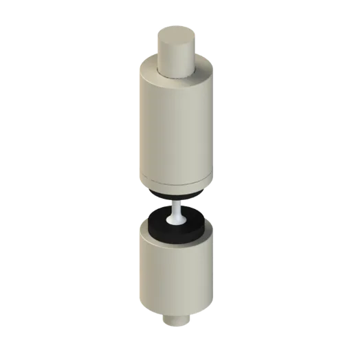
The machine capacity follows the force expected in the pull-out test, which ranges from hundreds of newtons for a fiber to hundreds of kilonewtons for a structural anchor. The table relates each application to its force range and model:
| Application | Range | Biopdi model |
|---|---|---|
| Single fibers, small inserts | 200 N to 1 kN | MBIOI-1P-M2 |
| Wood screws, bone screws, inserts in plastic | 2 to 10 kN | MBIOI-10-M2 |
| Fasteners, small anchors, thin bars | 5 to 50 kN | MBIOII-50-M2 |
| Bars in concrete, rebar | 100 to 200 kN | MBIOII-200-M2 |
| Structural anchors in concrete blocks | 300 to 1,000 kN | MBIOII-300-M2 and larger |
Field tests, with a hydraulic jack on site, are carried out by engineering firms and field testing laboratories; the universal testing machine is laboratory equipment. See also the testing software.
Other tests and technical references
Tests performed on the Biopdi universal testing machine



















Related technical references
NBR 5739 concrete compression test: fc calculation and the NBR 7222, NBR 12142 and NBR 6136-2 standards
ABNT NBR 5739:2018 (the Brazilian standard for concrete compression testing), reaffirmed in 2023, covers compression testing of cylindrical concrete specimens: continuous loading at 0.45 ± 0.15 MPa/s until failure and fc = 4F/(πD²), in MPa, to three significant figures. See what it requires of the machine and the specimen, the h/d correction, failure types A to G and the related standards: NBR 7222 (splitting tensile test), NBR 12142 (flexural tensile strength) and NBR 12118, withdrawn in February 2026 and replaced by NBR 6136-2:2026.
Crush test: ECT, FCT, RCT and BCT
The crush test compresses corrugated board until it collapses. See ECT, FCT, RCT, CMT and BCT, formulas, McKee, 32 ECT in kN/m, standards and examples.
Compression test: what it is, how to calculate it, concrete (NBR 5739 and fck) and standards
A compression test shortens a specimen until it fractures or yields. Learn to calculate compressive strength, plus NBR 5739, concrete fck and standards.
Frequently asked questions
What is a pull-out test?
It is the test that pulls an embedded element, such as an anchor, bar, soil nail or screw, until it is extracted from the base material or up to a proof load, measuring force and displacement. It gives the anchorage resistance and the bond stress.
Which standard applies to the pull-out test?
It depends on the element: ABNT NBR 14827 (Brazil) and ASTM E488 for anchors, NBR 5629 for ground anchors, NBR 16920-2 for soil nails, NBR 16325 for anchor devices for work at height, ASTM D1761 for wood and ASTM F543 for bone screws. For mortar, the test is a pull-off test, under NBR 13528.
How is the pull-out test performed?
In the field, with a hollow (center-hole) hydraulic jack bearing outside the cone, a pump with a pressure gauge and a dial gauge, applying the load in stages. In the laboratory, on a universal testing machine with a pull-out fixture and a load cell, recording the force × displacement curve up to failure.
What is the soil nail pull-out test?
It is the field test that pulls the nail with a hydraulic jack, in stages, reading the displacement of the nail head, to obtain the soil-nail interface resistance required by the design, under ABNT NBR 16920-2:2021 (the Brazilian soil nailing standard). The resistance is qs = F / (π·D·L).
What is the pull-out test for ceramic tiles?
It is a pull-off test: a metal dolly is bonded to the tile or coating and pulled perpendicularly to measure adhesion. It is explained in the article on bond (adhesion) testing.
What is a pull-out test (POT)?
It is the English name of the test. In the solar industry, the acronym POT refers to the pull-out test of the piles of photovoltaic mounting structures, which simulates wind uplift.
What is the difference between pull-out and pull-off?
The pull-out test extracts an embedded element, and the resistance comes from bond, friction, mechanical interlock or the breakout cone. The pull-off test pulls a dolly bonded to a layer, to measure the adhesion of that layer.
How do you calculate bond stress?
Divide the pull-out force by the lateral contact area: τ = F / (π·d·ℓ). A 10 mm bar with a 50 mm bonded length that pulls out at 18 kN has 11.5 MPa.
Why does an anchor pull out a concrete cone?
Because the tension spreads over a truncated cone around the anchor tip, with a radius of about 1.5 times the embedment depth. That is why the resistance increases with the embedment depth raised to the power 1.5 and with the square root of the concrete strength.
What is the proof load of an anchor?
It is defined in the design and lies above the service load and well below failure. In international practice, 1.5 times the applied load is used (BS 8539). The proof test verifies the installation; it does not measure the ultimate resistance.
Does Biopdi perform pull-out tests in the field?
No. Biopdi manufactures universal testing machines for the laboratory, which perform the pull-out test with a dedicated fixture and a complete curve up to failure. On-site testing uses a hydraulic jack and is carried out by engineering firms.