
An extensometer is an instrument that measures strain, and in Portuguese the word "extensômetro" covers two different devices. One is the strain gauge, a sensor bonded to the part whose electrical resistance changes with strain (ΔR/R = GF·ε, with a gauge factor GF ≈ 2). The other is the testing extensometer, which measures the elongation of the test specimen over a gauge length of 25 or 50 mm. A testing extensometer measures either between two knife edges clamped to the specimen or without contact, using a camera or a laser. The strain gauge is used for experimental stress analysis of parts and structures, and it is also the sensor inside load cells. The testing extensometer is the universal testing machine extensometer, the accessory you need to measure the modulus of elasticity or the offset yield strength correctly. Below we cover both in depth: the physics of the strain gauge, the Wheatstone bridge, the strain gauge rosette, the types of testing extensometer, the accuracy classes and some worked examples.
In short:
- Strain gauge (electrical resistance strain gauge): a metal grid bonded to the surface. It measures strain at one point, in the direction of the grid. The technique is called strain gauging.
- Testing extensometer: measures the change in length ΔL of a section L0 of the specimen, so the strain is ε = ΔL / L0. It can be a contact type (clip-on, long-travel) or a non-contact type (video, laser).
- Strain gauge signal: very small, on the order of millivolts per volt of excitation. That is why it is read with a Wheatstone bridge and an amplifier.
- Testing extensometer accuracy: classes defined by ISO 9513 (0.2, 0.5, 1 and 2) and ASTM E83 (A, B-1, B-2, C, D and E). The test standard sets the minimum class.
Strain gauge vs. extensometer: the two meanings of the word
Both instruments measure the same quantity: strain. Linear strain is the relative change in length, ε = ΔL / L0, where L0 is the initial length of the section being observed and ΔL is how much it changed. Since it is a ratio of two lengths, it has no unit (mm/mm). In the elastic range of metals the values are so small that microstrain is used: 1 µε = 10−6 mm/mm. A steel loaded in tension to 200 MPa strains about 1,000 µε, or 0.1%. Multiplying strain by the modulus of elasticity gives stress through Hooke's law, σ = E·ε, as long as the material stays in the elastic range and the loading is uniaxial.
The strain gauge is a grid-shaped resistor bonded to the surface of the part. When the part deforms, the grid deforms with it and its electrical resistance changes in proportion to the strain. It measures at one point (in practice, over the small area of the grid), in a single direction, and it stays bonded: it cannot be reused. In English, strain gauge refers only to this sensor. In Portuguese it is called an electrical resistance extensometer (extensômetro de resistência elétrica), an electrical extensometer or simply an extensometer, which is where the confusion comes from. The spelling strain gage, without the u, is the same word in its American form, used by ASTM E251 and by US manufacturers.
The testing extensometer (in Portuguese, extensômetro de ensaio) is a removable instrument attached to the specimen during the mechanical test. It measures the change in distance between two points on the specimen, separated by the gauge length, and gives the average strain over that section. The most common type, the clip-on, presses two knife edges against the specimen; non-contact types track marks with a camera or a laser. It is a reusable instrument, calibrated to ISO 9513 or ASTM E83.
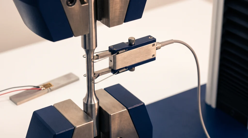
What separates the two is what they measure, not the technology inside. Many clip-on extensometers contain strain gauges bonded to a flexible arm and wired in a bridge: the resistive sensor is there, but the instrument measures the elongation between the knife edges, not the strain of the surface where the gauge is bonded. The photo shows both meanings of the word side by side: in the foreground, a clip-on extensometer held on the specimen by springs, with two knife edges marking the gauge length; in the background, a plate with a bonded strain gauge, the resistive sensor used in strain gauging.
The table summarizes the practical differences between the two:
| Aspect | Strain gauge | Testing extensometer |
|---|---|---|
| What it measures | local surface strain, in one direction | average elongation between two points on the specimen |
| Where it goes | bonded to the part, the structure or inside a transducer | attached to the specimen in the testing machine |
| Use | single use; stays on the part | reusable; removed at the end of the test |
| Typical range | small strains, in the elastic range | from modulus of elasticity measurement up to hundreds of percent, depending on the type |
| Reference standard | ASTM E251 (gauge characteristics) | ISO 9513 and ASTM E83 (calibration and class) |
How a strain gauge works
A modern strain gauge is a very thin metal foil, photo-etched into a zigzag pattern and bonded to an insulating polyimide backing, with two tabs for the lead wires. The zigzag has a purpose: it fits a long conductor into a short length. The long segments are aligned with the measuring axis and add up the resistance; the end loops are short and wide, so the grid barely responds to transverse strain. The principle was described by William Thomson, Lord Kelvin, in 1856, when he observed that the resistance of copper and iron wires changes when they are stretched. The sensor was invented independently in 1938 by Edward E. Simmons at Caltech and Arthur C. Ruge at MIT, at that time as a bonded wire gauge; the etched foil came later.
Why resistance changes with strain
The resistance of a conductor is R = ρ·L / A, where ρ is the resistivity of the material, L the length and A the cross-section. When the grid is stretched, three things happen at once: the length increases, the cross-section shrinks because of the Poisson effect, and the resistivity itself changes with the strain of the metal lattice, the piezoresistive effect. Differentiating the formula, the relative change becomes ΔR/R = (1 + 2ν)·ε + Δρ/ρ. The geometric part alone, with ν ≈ 0.3, would give a factor of 1.6. The copper-nickel alloy used in most gauges, constantan, has a factor of about 2: the difference comes from the resistivity.
This factor is the gauge factor, GF = (ΔR/R) / ε, stated by the manufacturer for each lot. Constantan is chosen because its GF is practically constant over a wide range of strain and temperature, and because the alloy can be treated to compensate for the thermal expansion of the part material, as we will see in the bridge section. For higher temperatures and long static measurements, manufacturers offer the nickel-chromium alloy Karma, which drifts less. Semiconductor (silicon) gauges have a factor on the order of 100 to 150, dozens of times that of constantan, but they are nonlinear and very sensitive to temperature, so they are limited to transducers with their own compensation.
The signal is small. With GF = 2, a strain of 1,000 µε on a 120 Ω grid changes the resistance by 120 × 2 × 0.001 = 0.24 Ω, or 0.2%. An ordinary ohmmeter cannot separate this from noise, lead wire resistance and thermal drift. That is why a strain gauge is always read with a Wheatstone bridge, with stable excitation and an amplifier.
120 Ω or 350 Ω
The most common nominal values are 120 and 350 Ω, and there are also 700 and 1,000 Ω gauges. The difference is heat. In a bridge excited at 5 V, the gauge sees half the voltage, 2.5 V, and dissipates P = V²/R: 52 mW at 120 Ω and 18 mW at 350 Ω. This heat flows through the adhesive into the part. In steel, a good conductor, it spreads out; in plastic or composite, it heats the grid and makes the reading drift. A 350 Ω gauge accepts more excitation for the same heating, which is why it dominates in transducers such as load cells. The 120 Ω gauge is common in general strain measurement. Educational modules for Arduino come in both values, the 120 Ω BX120 and the 350 Ω BF350, usually read by an HX711, a 24-bit analog-to-digital converter designed for weighing scales that already includes the bridge amplifier.
Wheatstone bridge: quarter, half and full bridge
A Wheatstone bridge is two voltage dividers in parallel, powered by the same excitation Vex. The output V0 is the difference between the midpoints of the two dividers. With all four arms equal, the bridge is balanced and V0 = 0: only the imbalance appears at the output, which is why it can read a 0.2% change without seeing the remaining 99.8%. For small strains, with all four arms being gauges of the same GF, the output is:
V0 / Vex ≈ (GF / 4)·(ε1 − ε2 + ε3 − ε4)
The rule that follows from this formula explains every wiring configuration: strains in adjacent arms subtract and strains in opposite arms add. An arm with a fixed resistor contributes zero. The diagram below shows the grid of a foil strain gauge and the three usual configurations, with the output of each for 1,000 µε, GF = 2.0 and 10 V excitation.
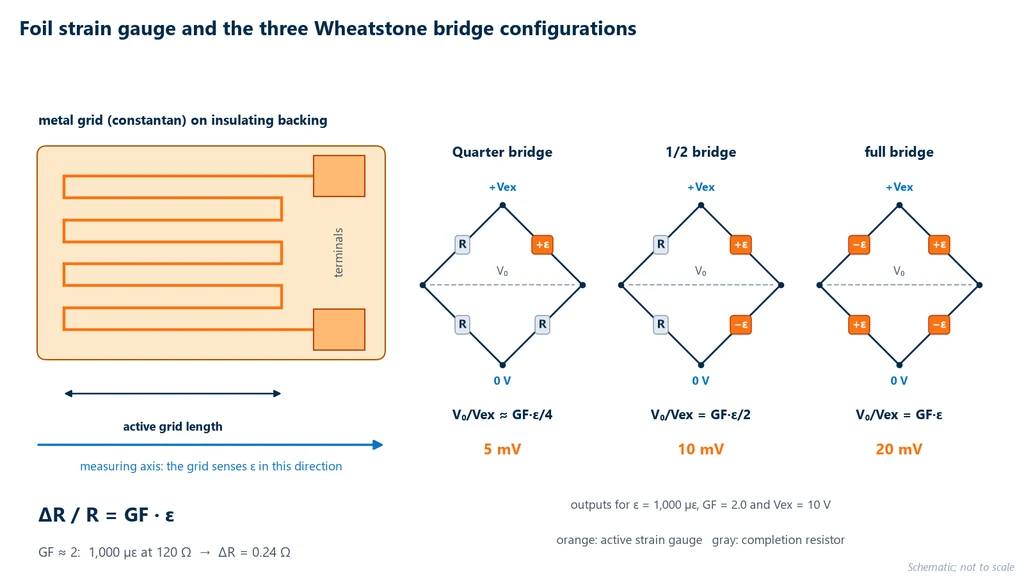
- Quarter bridge: one active gauge and three bridge completion resistors. V0/Vex ≈ GF·ε/4: 5 mV in the example. It is the simplest configuration and the most vulnerable to temperature and lead wires. The exact formula includes the factor 1/(1 + GF·ε/2): at 1,000 µε the linearity error is 0.1%; at 10,000 µε, 1%.
- Half bridge: two active gauges in adjacent arms. On a beam in bending, one on the tension face (+ε) and the other on the compression face (−ε): by the adjacent-arm rule, ε − (−ε) = 2ε, and the output doubles to GF·ε/2, 10 mV. Since both gauges are at the same temperature, the apparent strain of thermal origin is the same in both and cancels out.
- Full bridge: four active gauges, +ε in opposite arms 1 and 3 and −ε in arms 2 and 4. The output is GF·ε, 20 mV, with compensation for temperature and lead wires. This is the configuration used in load cells. On a bar in tension, which has no compression face, two axial and two transverse gauges give (GF/4)·2ε·(1 + ν) = GF·ε·(1 + ν)/2: the Poisson effect is what makes the transverse gauges contribute.
Temperature, lead wires and shunt calibration
A strain gauge bonded to an unloaded part changes its reading when the temperature changes. There are two causes: the resistivity of the grid varies with temperature, and the grid and the part expand differently, so the part "stretches" the grid without any applied force. This apparent strain is called thermal output. Self-temperature-compensated (STC) gauges have the alloy treated so that both causes cancel out on a specific material, such as steel or aluminum; bonded to a different material, the compensation no longer holds. The other solution is a compensating (dummy) gauge bonded to a piece of the same material, unloaded and at the same temperature, wired in the arm adjacent to the active gauge: the thermal output of the two subtracts.
Lead wires come into play in the quarter bridge. With a two-wire connection, the gauge is in series with both conductors in the same arm. If they add up to 1 Ω of copper and warm up by 10 °C, their resistance rises by about 1 × 0.0039 × 10 = 0.039 Ω, which the bridge reads as 0.039 / (120 × 2) = 163 µε of false strain. The three-wire connection puts one conductor in each adjacent arm, and the changes cancel out. Lead wire resistance also reduces sensitivity: 1 Ω in series with 120 Ω takes away about 0.8% of the signal, which is corrected in the signal conditioner.
To check the whole chain (gauge, lead wires, bridge, amplifier), shunt calibration is used: a resistor Rs of known value is connected in parallel with the gauge and simulates a strain of ε = −R / [GF·(R + Rs)]. With 120 Ω, GF = 2 and Rs = 59,880 Ω, the simulated strain is −1,000 µε; if the system indicates a different value, the error is in the measurement chain.
Amplification, filtering and sampling rate
A signal conditioner is the device that powers the bridge, amplifies the millivolt output and digitizes it. It does three things after the bridge. It amplifies the signal, with a gain of hundreds to thousands, to fill the range of the analog-to-digital converter. It filters, with a low-pass filter before digitization, the 60 Hz mains noise and frequencies above those of interest. And it samples at a rate suited to the phenomenon: by the Nyquist criterion, the sampling rate must be more than twice the highest frequency in the signal. A shaft at 1,800 rpm turns at 30 Hz; a strain that repeats once per revolution needs more than 60 samples per second, and in practice far more than that minimum to capture the waveform and the peak value. In static measurement, such as on a structure under permanent load, a few samples per second are enough, and the priority becomes zero stability.
Strain gauge rosette: principal strains when the direction is unknown
A rosette is a strain gauge with two or three grids on a single backing, at fixed angles. It measures the plane strain state when the principal direction is not known. A standard strain gauge measures only along the direction of its grid. On a bar in tension this is enough, because the direction of the principal strain is known. On a real part, such as the edge of a hole, a weld or the flange of a bracket, the strain state is biaxial and the principal direction is not known in advance. Three independent measurements are needed to determine it. The rosette combines three grids at fixed angles: 0°, 45° and 90° in the rectangular rosette, or 0°, 60° and 120° in the delta rosette. In stacked rosettes the three grids sit one on top of the other and measure at practically the same point. In planar rosettes they sit side by side, heat up less and measure over a slightly larger area. Micro-Measurements reports cases where the reading of a single grid differs from the principal strain by up to 130%. A misaligned uniaxial gauge does not give an approximate value; it gives a different value.
With the readings εa (0°), εb (45°) and εc (90°) of the rectangular rosette, the principal strains are:
ε1,2 = (εa + εc)/2 ± (1/√2)·√[(εa − εb)² + (εb − εc)²]
The in-plane shear strain is γ = 2εb − εa − εc, and the principal direction makes an angle θ with grid a given by tan 2θ = γ / (εa − εc), measured from grid a toward grid b. The quadrant is confirmed by substituting θ into the transformation equation. The principal stresses come from the generalized Hooke's law for plane stress, which uses Poisson's ratio ν: σ1 = E/(1 − ν²)·(ε1 + ν·ε2) and σ2 = E/(1 − ν²)·(ε2 + ν·ε1). Exercise 3 applies all three formulas.
Types of strain gauge by grid geometry
Strain gauge types differ in the number of grids and the angles between them, and each geometry suits a particular strain state:
- Uniaxial: one grid; used when the strain direction is known, as on a bar in tension or the face of a beam.
- Dual parallel: two grids side by side, in the same direction; provides redundancy or measures the strain gradient between two nearby points.
- Tee rosette (0/90°): two perpendicular grids; used when the principal directions are known, as when measuring Poisson's ratio.
- Three-grid rosette (0/45/90° or 0/60/120°): the general plane strain case, described above.
- Torsion or shear (±45°): two grids at 45° to the axis, in a herringbone (chevron) pattern; measures torque on shafts.
- Diaphragm: radial and circumferential grids in a circular pattern, bonded to the diaphragms of pressure transducers.
- Strip (chain): several small grids in a line; maps the strain gradient near a hole or a notch.
- Residual stress rosette: three grids around a central point where a small blind hole is drilled; the measured strain relief gives the residual stress by the ASTM E837 method.
The torsion gauge deserves a calculation. On the surface of a shaft in torsion the state is pure shear, and the principal strains lie at ±45° to the centerline, equal and of opposite sign, with magnitude γ/2. With four grids at ±45° in a full bridge, the signs add up and the output is V0/Vex = GF·γ/2; bending and axial load on the shaft cancel out. The shear strain γ gives the shear stress, τ = G·γ, with the shear modulus G, and from it the torque, T = τ·J/r, where J is the polar moment of inertia (π·d4/32 for a solid shaft) and r the radius. This is the principle of strain gauge torque transducers; the test that measures G and torsional strength is covered in the article torsion test.
The table summarizes the types and the use of each:
| Type | Grids | Typical use |
|---|---|---|
| Uniaxial | 1 | known direction: bars, beams |
| Tee rosette | 2, at 0/90° | known principal directions, Poisson's ratio |
| Rectangular or delta rosette | 3, at 0/45/90° or 0/60/120° | plane strain with unknown direction |
| Torsion | 2 or 4, at ±45° | torque on shafts, torque transducers |
| Diaphragm | 4, radial and circumferential | pressure transducers |
| Strip (chain) | 5 to 10 in a line | gradient near stress concentrations |
| Residual stress | 3 around a hole | hole-drilling method, ASTM E837 |
Strain gauge bonding and applications
A strain gauge only measures what the adhesive transmits. A poor bond does not give a slightly worse reading: it causes hysteresis, drift and debonding, which show up as strain. The sequence recommended by manufacturers follows the same logic in every case, and the curing times and temperatures come from the adhesive data sheet:
- degrease the area with solvent;
- abrade in crossing directions to create an anchoring roughness;
- mark the reference axes, which define the grid direction;
- clean with acid conditioner and then with neutralizer, until the swab comes away clean;
- position the gauge with tape, apply the adhesive (cyanoacrylate at room temperature, or heat-cured epoxy for high temperature and long-term measurements) and apply pressure during curing;
- solder the tabs and lead wires, with strain relief so the cable does not pull the gauge off;
- check the resistance and the electrical insulation to the part;
- protect against moisture and mechanical damage.
With the gauge properly bonded, strain gauge measurement (the technique of measuring strain with strain gauges and calculating the associated stresses) serves four groups of applications. The first is experimental stress analysis of prototypes, which validates finite element models, locates stress concentrations and records the in-service load history used in fatigue life calculations. The second is transducers: load cells, including those in scales, torque transducers and pressure transducers, in which an elastic element of known geometry converts force, torque or pressure into strain and the full bridge converts strain into a signal. The load cell of a universal testing machine is such a transducer; it measures force, not strain, because it was calibrated in force. The third is structural health monitoring of bridges, towers, cranes and aircraft, and predictive maintenance. The fourth is uses outside mechanical engineering, such as wearable sensors for breathing and posture in medical and rehabilitation research.
The materials testing extensometer
The testing extensometer is the instrument that measures the elongation of a length of the specimen itself during the mechanical test, and it is the machine's strain channel, alongside the load cell. The machine measures force with the load cell and crosshead displacement with the encoder, and neither of these is the strain of the material. The extensometer measures within the parallel length, where the cross-section is constant and the stress is the calculated one. Why this changes the result is explained in the extensometer section of the article tensile test; here the focus is the instrument.
The key quantity is the gauge length, the initial distance between the two measuring points, called L0 here. Note the notation used in the standards: ISO 9513 and ISO 6892-1 call the extensometer gauge length Le and reserve L0 for the original gauge length marked on the specimen, used for elongation after fracture. The two can be different. The other characteristics that define an extensometer are the travel, the largest elongation it can follow (for example, ±2.5 mm or 0 to +50 mm), and the resolution, the smallest change it can distinguish, in micrometers.
Anatomy of the clip-on extensometer
The clip-on is the most widely used type for metals and for the modulus of plastics. Two hardened steel knife edges rest on the specimen, one attached to a fixed arm and the other to a moving arm. Springs or elastic bands hold them against the surface, so that each knife edge follows the point of the specimen it rests on. When the length between them elongates, the moving arm is displaced and the transducer in the extensometer body converts that displacement into a signal: strain gauges on a flexural element, wired in a bridge, or an LVDT (linear variable differential transformer, an inductive displacement transducer). A pin or lock holds the distance between the knife edges at L0 during mounting and must be removed before the test starts. The diagram below shows a 50 mm clip-on extensometer on a round specimen with a 60 mm parallel length and compares the length it measures with the length the crosshead measures.
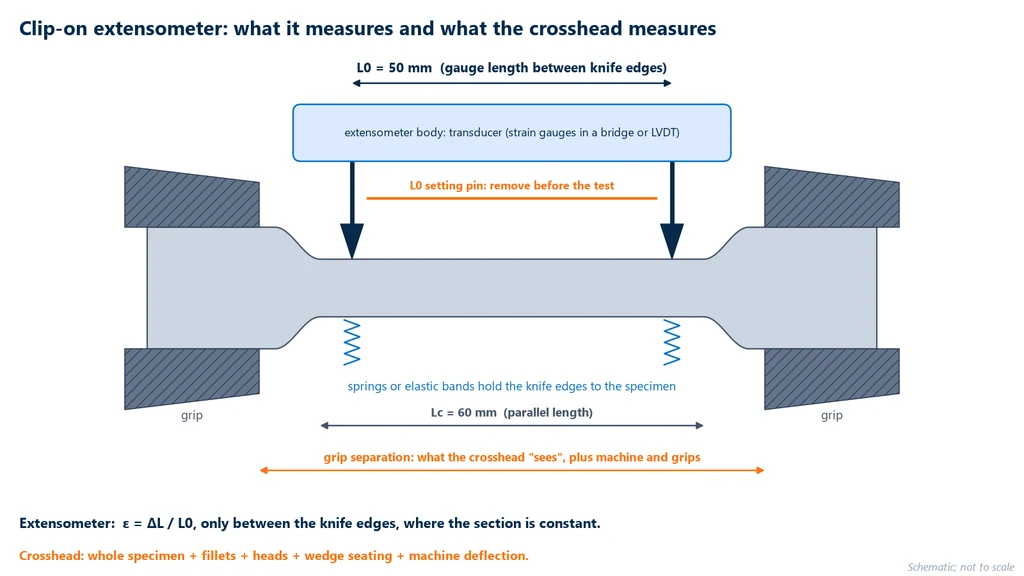
Two practical consequences follow from the diagram. The knife edges must sit within the parallel length, away from the transition radii, where the cross-section already increases; MTS recommends measuring within the central 70 to 80% of the reduced section. And the extensometer sees nothing outside the knife edges: if necking and fracture occur outside the gauge length, the elongation concentrated in the neck does not enter the reading. This is why a small-strain clip-on extensometer is usually removed after yielding, which also protects it from the energy released at fracture.
Types of testing extensometer
Apart from the clip-on, the other types handle situations where it is not suitable: large elongations, specimens too fragile for knife-edge contact, violent fractures and measurements that are not axial. The table below gathers the main ones, after the description of each:
- Long-travel: two follower arms attached to the specimen, which move apart with it over a travel of tens to hundreds of millimeters. This is the type used for elastomers, films and ductile plastics. The concern is the contact force, which must not mark or deform thin samples.
- Transverse or diametral: measures the change in width or diameter, used for Poisson's ratio together with an axial extensometer. ISO 9513 covers both, axial and diametral.
- COD clip gauge: measures the opening of a notch or crack in fracture mechanics tests. It does not measure axial strain.
- Deflectometer: measures the midspan deflection in the flexural test. It measures displacement, and the strain is obtained from the flexure formula.
- Video (non-contact): a camera tracks two marks on the specimen and calculates the distance between them in each frame. Nothing touches the sample, so fracture does not damage it and contact does not affect delicate materials. It requires marking, lighting and image calibration.
- Laser and digital image correlation (DIC): the laser tracks the natural surface pattern (speckle), without marking; DIC calculates the full strain field from a painted pattern, a typical research tool.
| Type | How it measures | Typical use |
|---|---|---|
| Clip-on | two spring-loaded knife edges; strain gauges or LVDT | metals and modulus of plastics: E, Rp0.2 |
| Long-travel | long-stroke follower arms | elastomers, films, ductile plastics |
| Transverse | change in width or diameter | Poisson's ratio |
| COD clip gauge | notch opening | fracture mechanics |
| Deflectometer | midspan deflection | flexural modulus |
| Video, laser, DIC | image, non-contact | violent fracture, delicate sample, strain field |
The name "extensometer" also appears in two other places. Old mechanical extensometers used dial indicators and levers and were read by eye; a "digital extensometer" is any extensometer with an electrical output read by the software. In geotechnics, the dial gauges that measure soil swell in the CBR test and the rod instruments installed in dams and slopes are also called extensometers, and they have nothing to do with the tensile test.
Accuracy classes: ISO 9513 and ASTM E83
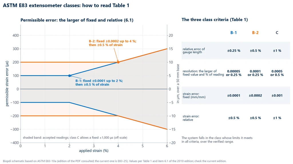
The accuracy class of an extensometer is the error limit it guarantees in calibration, defined by ISO 9513 (classes 0.2 to 2) or by ASTM E83 (classes A to E). The extensometer is calibrated statically: it is mounted on a calibrator, a rigid apparatus that imposes known displacements measured by interferometer, linear encoder or gauge blocks, and the extensometer readings are compared with those displacements. ISO 9513:2012, confirmed by ISO in 2022 and adopted in Brazil as ABNT NBR ISO 9513:2013, and ASTM E83 require an inspection of the instrument's condition before calibration, with replacement of worn parts such as the knife edges, and ask that the calibration apparatus have an error of no more than one third of the permissible error (in E83, sections 4.1 and 5.1 of the E83-10a edition, the one we read). The class of the system is the worst of three criteria: the gauge length error, the resolution and the indication error (bias). The permissible indication error is the larger of a relative value, as a percentage of the reading, and an absolute value, in micrometers.
ASTM E83-25 does the same with a different unit: the permissible error is the larger of a fixed error expressed in strain and a relative error. As in ISO, the E83 class also limits the gauge length error and the resolution: in class B-2, for example, ±0.5% gauge length error and a resolution of 0.0001 or 0.25% of the reading. These values come from Table 1 of E83-10a, the edition we read in PDF; check them against E83-25 before using them in a test report.
The class also has an expiry date. Under ASTM E83 (section 9 of E83-10a), the extensometer is verified once a year, unless the product or the customer requires more, and the interval between verifications never exceeds 18 months; after an adjustment or repair that may affect accuracy, it is verified again before returning to service. The verification covers the range of use with at least five strains per decade, in two runs.
Since one standard sets the absolute error in micrometers and the other in strain, comparing them depends on the gauge length. The table converts the limits of the classes most used in tensile tests to a 50 mm gauge length (ASTM side per E83-10a):
| Standard and class | Relative error | Absolute error | On a 50 mm gauge length |
|---|---|---|---|
| ISO 9513, class 0.5 | ±0.5% | ±1.5 µm | 30 µε |
| ISO 9513, class 1 | ±1% | ±3 µm | 60 µε |
| ASTM E83, class B-1 | ±0.5% | 0.0001 (100 µε) | 5 µm |
| ASTM E83, class B-2 | ±0.5% | 0.0002 (200 µε) | 10 µm |
The conversion dismantles an equivalence often repeated in the lab, that "class 1 is the same as B-1". On a 50 mm gauge length, the absolute error of class 1 (3 µm, 60 µε) is tighter than that of B-1 (100 µε). On a 25 mm gauge length, the same 3 µm equal 120 µε, and B-1 becomes the more demanding one. Both standards also have other classes: ISO 9513 has 0.2 and 2; ASTM E83 has A, which is stricter, and C, D and E, for progressively larger strains.
Using the values of the 2010 edition of ASTM E83, the one we consulted in PDF, the chart below plots the rule of the larger of the fixed and the relative error for classes B-1 and B-2: near zero the fixed error governs, and from 2% (B-1) or 4% (B-2) strain onward the relative error of 0.5% of the reading governs. Alongside are the three criteria that Table 1 requires simultaneously to grant the class: gauge length error, resolution and strain error.
The minimum class is set by the test standard, not by the extensometer standard. In tensile testing of metals, ISO 6892-1 requires class 1 or better for proof strength, Rp and Rt, and accepts class 2 for properties at strains above 5% (section 9, checked against ABNT NBR ISO 6892-1:2024, the Brazilian adoption); ASTM E8 requires B-2 for offset yield, as detailed in the article ASTM E8 and ISO 6892-1. In tensile testing of plastics, ASTM D638 requires B-2 for the modulus and accepts class C up to about 20% strain, as explained in the article ASTM D638. ASTM E111, the method dedicated to the modulus of elasticity, requires B-1 or better.
Why the crosshead cannot measure the modulus: the machine in series
Crosshead displacement does not measure the modulus of elasticity because it adds the elastic deformation of the machine and grips, and the seating of the wedges, to the elongation of the test specimen. The tensile test article already shows the consequence: the same steel gives 205 GPa with the extensometer and an apparent modulus of about 34 GPa from the crosshead. The remaining question is why the error is so large in steel and so much smaller in other materials. The answer is that the specimen and the rest of the system act as two springs in series. The same force passes through both, and the crosshead displacement is the sum of the two elongations:
ΔLcrosshead = F·(Lc / (E·S0) + Cs)
The first term is the parallel length of the specimen, of length Lc and cross-section S0. The second, Cs, is the system compliance, in mm per kN: the elastic deformation of the columns, the load cell and the adapters, the elongation of the specimen heads and fillets, and the seating of the wedges. Dividing by the parallel length, the apparent modulus becomes Eapp = E / (1 + Cs·ksp), where ksp = E·S0/Lc is the specimen stiffness. The error grows with that stiffness. A 12.5 mm steel specimen has ksp ≈ 419 kN/mm, four times the stiffness of the system in Exercise 2 (about 103 kN/mm), and the apparent modulus drops to one fifth. A Type I polycarbonate specimen (13 × 3.2 mm, E ≈ 2.4 GPa, 57 mm parallel length) has ksp ≈ 1.75 kN/mm, and the same system would take away only 1.7% of the modulus. In plastics, the crosshead error comes from other effects, such as slippage in the grips and deformation of the specimen heads, described in the tensile test article.
There is a compliance correction: measure Cs with a rigid specimen and subtract it. It helps in tests where the standard accepts corrected displacement, but it does not solve wedge seating, which is neither linear nor repeatable from one test to the next, and it does not replace the extensometer when the standard requires one. Exercise 2 redoes the full calculation and shows where every tenth of a millimeter goes.
How to choose an extensometer: gauge length, travel, class and contact
Choosing a testing extensometer means answering four questions, in this order: what gauge length, what travel, what class, and whether contact with the specimen is acceptable.
- What gauge length do the standard and the specimen allow? The gauge length must fit within the parallel length with room to spare. A 50 mm extensometer suits the 12.5 mm round specimen of ASTM E8 and the Type I specimen of ASTM D638; smaller specimens call for 25 mm. For the same absolute error, a longer gauge length gives a smaller relative error and an average over a longer section.
- What travel does the test require? The maximum elongation is ΔL = εmax × L0. For modulus and yield of metals a few millimeters are enough; for elastomers, which stretch several times their initial length, travel reaches hundreds of millimeters (Exercise 4).
- What class does the test standard require? See the previous section. The class applies to the calibrated range: an extensometer calibrated only over the first few millimeters has no guaranteed class at the end of its travel. It also applies downward only to a point: under ASTM E83, the smallest strain verified must be at least 100 times the resolution of the indicator, and below it the class is not guaranteed.
- Contact or non-contact? The clip-on type suits most metals and rigid plastics. Violent fractures, such as those of high-strength steels and composites, call for removal before fracture or non-contact measurement. Films, fibers and soft materials can be marked by the knife edge and break at it; in these cases, low contact force arms or video.
Solved exercises
The four exercises cover both meanings of the term: reading a strain gauge, the modulus measured with a testing extensometer, the rosette and the choice of travel.
Exercise 1: strain and stress from a strain gauge
A 120 Ω strain gauge with GF = 2.1 is bonded to a steel bar in tension, along its axis (E = 200 GPa). With the load applied, the resistance increased by 0.084 Ω. Calculate the strain, the stress and the output of a quarter bridge excited at 5 V.
- Relative change: ΔR/R = 0.084 / 120 = 7.00 × 10⁻⁴.
- Strain: ε = (ΔR/R) / GF = 7.00 × 10⁻⁴ / 2.1 = 3.333 × 10−4 = 333 µε.
- Stress, in the elastic and uniaxial regime: σ = E·ε = 200,000 MPa × 3.333 × 10−4 = 66.7 MPa.
- Bridge output: V0 ≈ Vex·GF·ε/4 = 5 × 2.1 × 3.333 × 10−4 / 4 = 8.75 × 10⁻⁴ V = 0.875 mV. The nonlinearity factor, 1/(1 + GF·ε/2) = 0.99965, changes the result to 0.8747 mV: negligible at this strain level.
If the conditioner were set to GF = 2.0 instead of 2.1, the indicated strain would be 7.00 × 10⁻⁴ / 2.0 = 350 µε, 5% above the real value, and the calculated stress 70.0 MPa. The gauge factor error passes entirely into the result.
Exercise 2: modulus of steel from the extensometer and from the crosshead
A round steel specimen, with d = 12.5 mm, parallel length Lc = 60 mm and Rp0.2 around 350 MPa, is tested with a clip-on extensometer with L0 = 50 mm. Between F1 = 4 kN and F2 = 28 kN, in the elastic range, the extensometer measures ΔL = 0.0477 mm, and the crosshead moves 0.290 mm (illustrative value). Calculate the modulus from both readings.
- Cross-section: S0 = π × 12.5² / 4 = 122.7 mm².
- Stresses: σ1 = 4,000 / 122.7 = 32.6 MPa; σ2 = 28,000 / 122.7 = 228.2 MPa; Δσ = 195.6 MPa. The upper point is well below yield.
- Extensometer: Δε = 0.0477 / 50 = 9.54 × 10⁻⁴; E = 195.6 / 9.54 × 10−4 = 205,000 MPa = 205 GPa.
- Crosshead, dividing by the parallel length: apparent Δε = 0.290 / 60 = 4.83 × 10⁻³; apparent E = 195.6 / 4.83 × 10−3 = 40.5 GPa, about 5 times lower.
- Diagnosis: the parallel length, with the real strain of 9.54 × 10⁻⁴, elongates 9.54 × 10−4 × 60 = 0.057 mm. The other 0.290 − 0.057 = 0.233 mm come from the system, which gives Cs = 0.233 / 24 = 0.0097 mm/kN, or a stiffness of about 103 kN/mm.
The chart below shows the two lines from the same test and, alongside, the breakdown of the 0.290 mm measured by the crosshead:
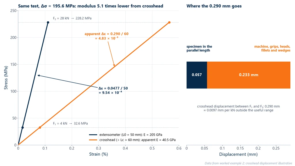
The calculation also shows why class matters for the modulus. The extensometer measured only 47.7 µm. The absolute limit of ISO 9513 class 1, 3 µm, equals 6% of that interval; that of class 0.5, 1.5 µm, equals 3%. The class guarantees a limit, not the actual error, but the calculation explains two practices: using the largest possible force interval within the elastic range and preferring, for the modulus, an extensometer of a better class than the one required for yield.
Exercise 3: rectangular rosette on a steel plate
A 0/45/90 rosette bonded to a steel plate (E = 200 GPa, ν = 0.30) reads εa = 600 µε, εb = 400 µε and εc = −200 µε. Calculate the principal strains and stresses and the principal direction.
- Center: (εa + εc)/2 = (600 − 200)/2 = 200 µε.
- Radius: (1/√2)·√[(600 − 400)² + (400 + 200)²] = 0.7071 × √(40,000 + 360,000) = 0.7071 × 632.5 = 447.2 µε.
- Principal strains: ε1 = 200 + 447.2 = 647.2 µε; ε2 = 200 − 447.2 = −247.2 µε.
- Direction: γ = 2 × 400 − 600 − (−200) = 400 µε; tan 2θ = 400 / (600 + 200) = 0.5; 2θ = 26.6° and θ = 13.3°, from grid a toward grid b. Check: ε(13.3°) = 200 + 400 × cos 26.6° + 200 × sin 26.6° = 200 + 357.8 + 89.4 = 647.2 µε.
- Plane stress factor: E/(1 − ν²) = 200,000 / 0.91 = 219,780 MPa.
- Stresses: σ1 = 219,780 × (647.2 + 0.3 × (−247.2)) × 10−6 = 219,780 × 573.0 × 10−6 = 125.9 MPa; σ2 = 219,780 × (−247.2 + 0.3 × 647.2) × 10−6 = 219,780 × (−53.0) × 10−6 = −11.7 MPa.
Note that σ1 = E·ε1 would give 129.4 MPa, and grid a alone, 600 µε × 200 GPa = 120 MPa. Neither shortcut gives the principal stress: in the biaxial state you need the rosette and the generalized Hooke's law.
Exercise 4: extensometer travel for an elastomer
An elastomer is to be tested to fracture, which occurs near 300% elongation, with a 50 mm gauge length. What travel does the extensometer need?
- Maximum elongation: ΔL = εmax × L0 = 3.00 × 50 = 150 mm.
- A 50 mm clip-on with 0 to +50 mm travel covers only up to 100%: it will not do.
- A long-travel extensometer with 150 mm travel reaches exactly the limit, with no margin for scatter between specimens; one with 250 mm gives headroom. If the material reaches 500%, the same calculation gives 250 mm.
- With a 25 mm gauge length, when the product standard allows it, 300% requires 75 mm of travel.
How to interpret: common questions about interpretation
The questions below cover the points where a strain gauge or extensometer reading is most often misinterpreted.
Is the strain gauge reading the stress in the part?
Not directly, and not always the total stress. The gauge is zeroed after it is bonded, so it only measures the change in strain from that moment on: residual stresses from manufacturing and permanent loads already acting on the part do not appear. In addition, σ = E·ε only holds in the elastic range and under uniaxial loading along the grid direction; in a biaxial stress state, the conversion requires a rosette and Poisson's ratio, as in exercise 3.
Why do two tests on the same material give different moduli, even with an extensometer?
The most frequent cause is parasitic bending. With some misalignment of the grips, the specimen bends slightly, and a clip-on extensometer attached to one side only reads the strain on that face, which is higher or lower than the average. Two extensometers on opposite sides, or an averaging extensometer, cancel the bending. The other causes are a force interval that is too small, where the absolute error of the class becomes significant, and choosing points outside the linear portion.
Does a 50 mm extensometer measure twice the strain of a 25 mm one?
No. With uniform strain, both measure the same strain; the 50 mm extensometer measures twice the elongation ΔL. The classic mistake is the opposite: the wrong gauge length set in the software. A 25 mm extensometer declared as 50 mm delivers half the strain and twice the modulus.
Is the extensometer elongation the elongation after fracture?
Only if it stayed on until fracture and the fracture occurred between the knife edges. In practice, the clip-on is removed after yielding, and the elongation after fracture is measured by fitting the two halves together and measuring the distance between the gauge length marks, which may differ from the extensometer gauge length.
Is a step or a negative portion at the start of the curve material behavior?
Almost never. At the start of the test, the knife edges settle and the specimen aligns in the grips; a knife edge that slips produces a step, and a poorly seated knife edge can record apparent shortening. A small preload before zeroing the extensometer and a visual check of the knife edges solve most cases.
Can a strain gauge bonded to the specimen replace the extensometer?
In the elastic range, it can. Gauges bonded on opposite faces are common in composites and in Poisson's ratio measurements, because they measure small strains with high resolution. But they measure at a single point, debond or break when the material yields, and are lost with every specimen. For yield and elongation, the test extensometer is still necessary.
Common mistakes
The mistakes below are frequent in the laboratory, half in strain gauging and half in the test itself:
- Forgetting the gauge length setting pin on the clip-on. The extensometer stays locked, records nothing and may break.
- Removing the clip-on too late. Fracture releases elastic energy that damages knife edges and arms. Schedule removal after yielding or use non-contact measurement.
- Worn knife edges or loose springs. The knife edge slips and the curve shows steps. ISO 9513 includes the knife edges in the inspection that precedes calibration.
- Insufficient travel for polymers and elastomers (exercise 4).
- A class lower than required by the test standard, a calibration that does not cover the range used, or an expired calibration: under ASTM E83, the interval is annual and never exceeds 18 months.
- Strain gauge wired two-wire in a quarter bridge, with leads exposed to temperature changes: every degree becomes false strain.
- Self-temperature-compensated gauge for the wrong material, such as a gauge for steel bonded to aluminum.
- High excitation on a 120 Ω gauge on plastic or composite: self-heating and drift.
- Wrong GF in the signal conditioner: the error passes entirely into the strain.
- Poorly prepared surface: hysteresis and debonding, read as strain.
Extensometers for the Biopdi universal testing machine
Biopdi manufactures universal testing machines and works with the second meaning of the word: the test extensometer, which serves as the strain channel alongside the load cell. The M2 line has clip-on extensometers with L0 from 25 to 100 mm, for small strains, modulus of elasticity and offset yield strength, long-travel extensometers with up to 250 mm of travel, for polymers and elastomers, deflectometers for flexural tests, and COD clip gauges. The extensometers for universal testing machines page shows which one to choose for each test and standard, with codes, L0 and travel. The BioLab software reads up to 4 extensometer channels at the same time, which allows more than one extensometer to be combined in the same test. The load cell is itself a transducer with strain gauges, and the machine's force measuring system, with the load cell installed, is verified to ABNT NBR ISO 7500-1:2023 (the Brazilian adoption of ISO 7500-1). The panel below shows the machine, the role of each part in strain measurement, and the extensometers.
The universal testing machine in strain measurement
The M2 line has single-column models, from 200 N to 10 kN, and dual-column models, from 5 kN to 1,000 kN. Each part of the machine has a role in the measurement:

- Moving crosshead applies the displacement at the speed set by the standard
- Load cell measures force, class 1
- Grips hold and align the specimen
- Extensometer measures elongation over the gauge section
- BioLab software up to 4 extensometer channels, modulus and Rp0.2
- Control panel and emergency stop positions and stops the test
M2 line extensometers
The extensometers below are mounted on the same machine, depending on the material and the standard:
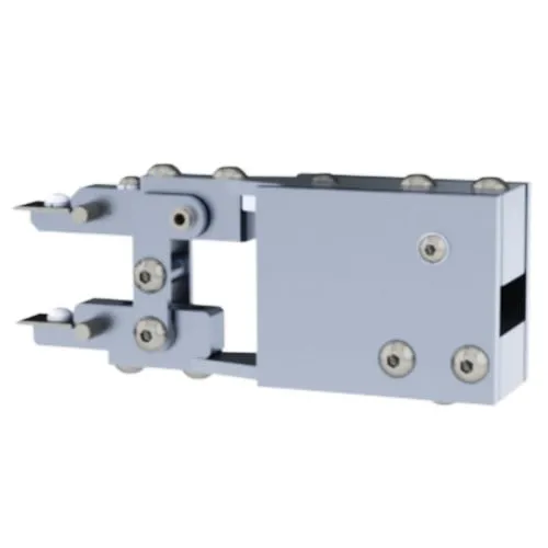
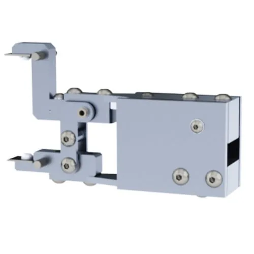
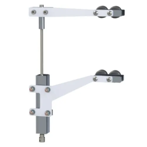
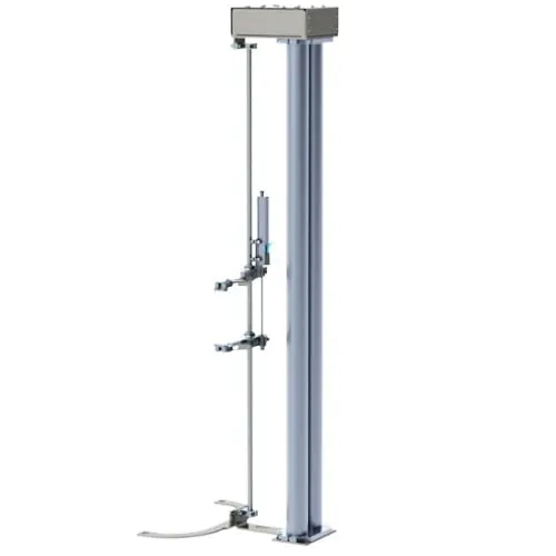
The machine also has to keep up with the extensometer. For materials that elongate by hundreds of percent, crosshead travel is the limit: the extended column reaches 1,290 mm. The table shows the model by application:
| Application | Extensometer | Biopdi model |
|---|---|---|
| Modulus of plastics (D638, ISO 527) | 50 mm clip-on | MBIOI-10-M2 (2 to 10 kN) |
| High-elongation elastomers and films | long-travel, 150 or 250 mm of travel | MBIOI-10-M2 with extended column |
| Sheet, fasteners, machined bars | 25 or 50 mm clip-on | MBIOII-50-M2 (5 to 50 kN) |
| Rebar and bars | 50 mm clip-on | MBIOII-200-M2 (100 to 200 kN) |
Standards for strain gauges and extensometers
The standards below cover the instrument (calibration and class) or require an extensometer of a defined class. Editions were checked on September 30, 2026; those of ASTM E83, E251 and E837 were checked again on October 1, 2026:
| Standard | Subject | Current edition |
|---|---|---|
| ISO 9513 | calibration and classes of extensometers, contact and non-contact | 2012, confirmed in 2022 |
| ABNT NBR ISO 9513 | Brazilian adoption of ISO 9513 | 2013, confirmed in 2024 |
| ASTM E83 | calibration, verification and classification of extensometers | E83-25 |
| ASTM E251 | performance characteristics of bonded metallic strain gauges (GF, thermal output, transverse sensitivity) | E251-20a |
| ASTM E837 | residual stress by the hole-drilling method with a strain gauge rosette | E837-25e1 |
| ASTM E111 | Young's modulus, tangent and chord modulus | E111-17, reapproved in 2025 |
| ABNT NBR ISO 6892-1 | tensile testing of metals at room temperature (Brazilian adoption of ISO 6892-1) | 2024 |
| ASTM E8/E8M | tensile testing of metals | E8/E8M-25 |
| ASTM D638 | tensile testing of plastics | D638-22 |
| ABNT NBR ISO 7500-1 | verification of machine force (load cell), Brazilian adoption of ISO 7500-1 | 2023 |
Other tests and technical references
Tests performed on the Biopdi universal testing machine



















Related technical references
ASTM E8 vs ISO 6892-1: tensile testing of metals, differences and requirements (NBR ISO 6892-1 and A370)
ASTM E8/E8M-25 and ISO 6892-1:2019, adopted in Brazil as ABNT NBR ISO 6892-1:2024, cover the same tensile test of metals at room temperature. They differ in the specimen gauge length (4D in E8, 5D in E8M and 5.65√S0 in ISO), in speed control and its tolerance, in symbols, in rounding and in the standards for the machine and the extensometer. For that reason, elongation from one cannot be compared directly with elongation from the other.
NBR 5739 concrete compression test: fc calculation and the NBR 7222, NBR 12142 and NBR 6136-2 standards
ABNT NBR 5739:2018 (the Brazilian standard for concrete compression testing), reaffirmed in 2023, covers compression testing of cylindrical concrete specimens: continuous loading at 0.45 ± 0.15 MPa/s until failure and fc = 4F/(πD²), in MPa, to three significant figures. See what it requires of the machine and the specimen, the h/d correction, failure types A to G and the related standards: NBR 7222 (splitting tensile test), NBR 12142 (flexural tensile strength) and NBR 12118, withdrawn in February 2026 and replaced by NBR 6136-2:2026.
Weld test specimen: tensile and bend tests per ASME IX, AWS and ISO
Weld test specimen: how to cut, machine and run tensile and bend tests per ASME IX and ISO 15614-1, with the 3 mm and 95% criteria and examples.
Frequently asked questions
What is an extensometer used for?
To measure strain. A bonded strain gauge measures the local strain of parts, structures and the elastic elements of transducers, such as load cells. A test extensometer measures the elongation of the specimen in the universal testing machine, to calculate the modulus of elasticity, the offset yield strength and the elongation.
What is the difference between an extensometer and a strain gauge?
A strain gauge is an electrical resistance strain sensor: a bonded grid that measures strain at a point through the change in resistance (ΔR/R = GF·ε). An extensometer is the test instrument that measures the elongation between two knife edges attached to the specimen, or without contact. Many test extensometers use strain gauges internally, but they measure something else. Strain gage is the same word in American spelling.
What are electrical strain gauges?
They are electrical resistance strain gauges, made of wire or metal foil, bonded to the surface of the part, whose resistance changes in proportion to strain (ΔR/R = GF·ε). The name distinguishes them from mechanical strain gauges, with dial indicators and levers, and from test extensometers, which are removable instruments.
What are the types of extensometers?
Among strain gauges: uniaxial, rosette (0/45/90 or 0/60/120), chain and diaphragm, in metal foil or semiconductor. Among test extensometers: clip-on, long-travel, transverse, clip gauge for crack opening (COD), deflectometer for flexural tests, and non-contact types, based on video, laser or digital image correlation.
How does a strain gauge work?
The metal grid stretches together with the part, becomes longer and thinner and changes resistivity, and its resistance increases: ΔR/R = GF·ε, with GF ≈ 2 for constantan. Since 1,000 µε on a 120 Ω grid gives only 0.24 Ω, the reading is taken with a Wheatstone bridge and an amplifier.
How does a strain gauge measure force?
Indirectly: the strain gauges are bonded to an elastic element of known geometry, the force deforms that element, and the full bridge converts the strain into millivolts. This assembly is the load cell used in scales and testing machines, calibrated in force against standards, with a typical output of 2 mV/V at rated capacity.
What is the difference between an LVDT and a strain gauge?
An LVDT measures displacement, and a strain gauge measures strain. The LVDT is a differential transformer with a moving core, with no electrical contact between the parts and reusable, reading from micrometers to centimeters; the strain gauge is bonded and measures the local strain of the surface. In a test extensometer, either one can be the internal transducer that converts the movement of the knife edges into a signal.
How much does a strain gauge cost?
It depends on the category. BF350 educational modules for Arduino are the cheapest, sold individually in electronics stores; laboratory strain gauges, with a gauge factor certified per batch and self-temperature compensation for the material, cost more and are sold in packs; a test extensometer calibrated to ISO 9513 or ASTM E83 is a precision instrument, quoted together with the testing machine.
What is a digital extensometer?
It is an extensometer whose output is an electrical signal (from strain gauges, an LVDT, an encoder or a camera) read and recorded by software, instead of a dial indicator read by eye. On the universal testing machine, it serves as a strain channel alongside the load cell.
What is strain gauge measurement?
It is the experimental technique of measuring strains with strain gauges and calculating the associated stresses. It is used in stress analysis of prototypes, in structural monitoring and in building force, torque and pressure transducers.
Why not use crosshead displacement to calculate the modulus?
Because it adds the deformation of the machine, the grips, the specimen heads and the seating of the wedges. In the exercise in this article, the steel gives 205 GPa from the extensometer and 40.5 GPa from the crosshead: of the 0.290 mm of crosshead travel, only 0.057 mm belonged to the parallel length.
What extensometer class is required in the tensile test?
It depends on the test standard. ISO 6892-1 requires ISO 9513 class 1 or better for proof strength (Rp and Rt) and allows class 2 above 5% strain; ASTM E8 requires ASTM E83 class B-2; ASTM D638, B-2 for the modulus of plastics; ASTM E111, B-1 or better for the modulus.
How often is the extensometer calibrated?
Under ASTM E83, once a year, unless the product or customer requires more, and never at an interval longer than 18 months. After an adjustment or repair that may affect accuracy, it is verified again before use. The interval comes from section 9 of E83-10a, the edition we read.
Which gauge length to use: 25 or 50 mm?
The one that fits in the parallel length of the standard specimen, with the knife edges away from the fillets. The 50 mm suits the 12.5 mm round specimen of ASTM E8 and the type I specimen of ASTM D638; the 25 mm suits smaller specimens.
When should a non-contact extensometer be used?
When fracture is violent and would damage the clip-on, when the sample is too thin or too soft for knife edge contact (films, fibers, biological tissues), when the strain is very large, or when the test is performed at elevated temperature.
120 or 350 Ω strain gauge?
The 350 Ω gauge dissipates about one third of the heat of the 120 Ω gauge at the same voltage (P = V²/R), accepts higher excitation and dominates in transducers. The 120 Ω gauge is common in general strain measurement and in educational modules.