
ASTM D790 is the American standard for measuring the flexural properties of unreinforced and reinforced plastics and electrical insulating materials, using a bar supported at both ends and loaded at midspan (three-point bending). The current edition is ASTM D790-25. It requires a span of 16 times the thickness. The crosshead speed is calculated with R = ZL²/6d, using a strain rate of 1%/min in Procedure A or 10%/min in Procedure B. The test ends when the specimen breaks or when the outer fiber reaches 5% strain. Flexural strength comes from σf = 3PL/(2bd²), and the modulus comes from the initial slope of the load-deflection curve.
In short:
- Preferred bar: 127 × 12.7 × 3.2 mm, with a 51.2 mm span.
- Speed for this bar: 1.37 mm/min in Procedure A and 13.7 mm/min in Procedure B.
- End of test: break, or 5% strain, which for this bar is a deflection of 6.83 mm.
- Old editions: the D790-00, D790-10 and D790-17 PDFs found online have been superseded.
- Other standards: ISO 178:2019 covers the same subject with a different specimen and a different modulus. Four-point flexural testing of plastics is covered by ASTM D6272-25.
What ASTM D790 covers
The principle of the flexural test (the neutral axis, the bending moment diagram and the difference between three-point and four-point bending) is explained in the article on flexural testing. This guide covers what D790 adds to that principle: the required geometry, the calculated speed, the strain limit, the corrections and how deflection is measured. This is the standard behind the flexural modulus and flexural strength values on resin and compound datasheets.
The full title is Standard Test Methods for Flexural Properties of Unreinforced and Reinforced Plastics and Electrical Insulating Materials. The scope covers unreinforced and reinforced plastics, including high-modulus composites, and electrical insulating materials, as long as they are rigid or semirigid. The specimen has a rectangular cross section and can be molded or cut from sheets, plates and shapes. The scope itself warns that flexural strength cannot be determined for a material that neither breaks nor yields in the outer surface up to 5.0% strain.
The test gives three results: flexural strength, the maximum stress in the outer fiber; flexural strain, the relative elongation of that fiber at midspan; and the flexural modulus, the stiffness of the material in the elastic region.
Do not confuse it with ASTM D638. D638 is the tensile test for plastics, with a dogbone specimen held in grips. D790 is the flexural test, where the bar simply rests on supports. Neither one replaces the other, and the guide to ASTM D638 explains tensile testing. D790 itself suggests D638 for characterizing a material that neither breaks nor yields in flexure up to the 5% limit.
About the edition: the ASTM store lists D790-25 as active, and the published summary keeps the scope, Procedures A and B, the 5% limit and the two ways of measuring deflection. We checked the numerical requirements below against the full text of D790-03. Points that may have changed by D790-25 are flagged, and anyone auditing a laboratory should confirm them in a copy of D790-25.
Setup: three-point fixture, specimen and span
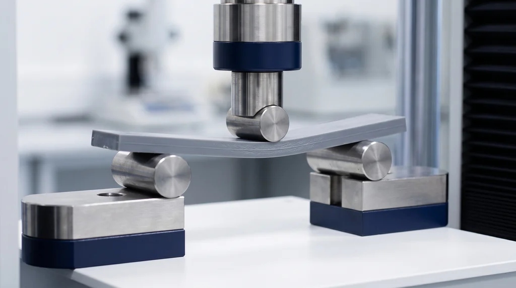
The bar lies flat on two cylindrical supports, and the cylindrical loading nose, attached to the machine crosshead, comes down at midspan. The top face is in compression and the bottom face in tension. The photo shows a plastic bar in a three-point bend fixture: two support rollers, and the loading nose at midspan coming down and bending the bar.
The radius of the loading nose and supports is 5.0 ± 0.1 mm, unless the material specification or an agreement between the parties says otherwise. Other radii are allowed to avoid excessive indentation: at least 3.2 mm for the loading nose and supports, up to 1.6 times the thickness for the supports (bars 3.2 mm thick or more) and up to 4 times the thickness for the loading nose. The radii used must be reported.
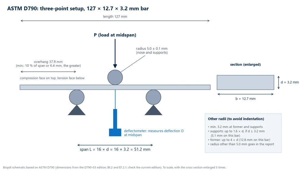
The preferred specimen for thermoplastic and thermoset molding materials measures 127 × 12.7 × 3.2 mm. The thickness d is the dimension in the direction of loading, which the standard calls the depth of the beam. For sheet 1.6 mm thick or more, the width is 12.7 mm when d ≤ 3.2 mm and must not exceed one quarter of the span when d > 3.2 mm. The bar must overhang each support by at least 10% of the span, and never less than 6.4 mm, so it does not slip into the span.
The span L is (16 ± 1) times the thickness and must be set to within 1% of the calculated value. For the 3.2 mm bar, L = 16 × 3.2 = 51.2 mm. With an adjustable-span fixture, the span is measured (to 0.1 mm below 63 mm and to 0.3 mm above), and the measured value goes into the calculations. The drawing below shows this setup to scale. The overhang is 37.9 mm on each side of the 127 mm bar, well above the minimum (10% of the span or 6.4 mm, whichever is greater). The deflectometer, the instrument that measures deflection, sits under the bar at midspan. The box on the right gives the radius limits when the 5.0 mm radius is not used: at least 3.2 mm, up to 1.6 times the thickness for the supports and up to 4 times for the loading nose.
The 16:1 ratio works when the material's tensile strength is less than eight times its shear strength. Composite laminates with low in-plane shear strength and high tensile strength along the span need larger ratios, 32:1 or 40:1, so that the bar fails in flexure at the outer fiber and not by interlaminar shear. To measure the modulus of highly anisotropic composites, the standard recommends 60:1, because even at 40:1 shear deformation lowers the apparent modulus. In that case, strength is measured on a second set of bars with a shorter span.
Four requirements complete the preparation:
- Number of bars: at least five per sample for isotropic or molded material. For anisotropic sheet, five in each direction tested, and the direction must be reported.
- Very thin sheet: below 1.6 mm, the standard uses a 50.8 × 12.7 mm bar with a 25.4 mm span, and allows wider bars or a shorter span as long as the span-to-depth ratio stays at 14:1 or more.
- Measurement: width and thickness are measured at midspan to 0.03 mm, or to 0.003 mm for the thickness of bars under 2.54 mm. The measured values go into the calculations, not the nominal ones.
- Conditioning: per Procedure A of ASTM D618-21, unless the contract or material specification requires otherwise. In the 2003 edition of D790, this meant at least 40 h at 23 ± 2 °C and 50 ± 5% relative humidity, with the test run in the same atmosphere. Check the tolerances in the current edition. Plastics that absorb water, such as polyamide, change stiffness considerably with humidity.
Procedures A and B and the crosshead speed
D790 does not set a speed in mm/min. It sets the outer fiber strain rate, Z, and the crosshead speed is calculated for each geometry:
R = Z·L² / (6·d), with R in mm/min, L and d in mm and Z in mm/mm/min.
The formula comes from the relationship between deflection and strain in a simply supported beam, ε = 6Dd/L². For strain to increase by Z per minute, deflection has to increase by ZL²/(6d) per minute. The actual speed must stay within 10% of the calculated value. Since L scales with thickness, a thicker bar tested at 16:1 also needs a higher speed.
The two procedures differ in strain rate:
- Procedure A: Z = 0.01 mm/mm/min, or 1%/min. This is the preferred procedure, and the standard requires it for measuring flexural properties, especially the modulus, unless the material specification says otherwise. It was designed for materials that break at small deflections.
- Procedure B: Z = 0.10 mm/mm/min, or 10%/min. It is for material that neither breaks nor yields up to 5% when tested with Procedure A: the rate ten times higher can make it yield or break within the limit. Procedure B is only for flexural strength. The modulus still comes from Procedure A.
The table summarizes the two procedures for the 3.2 mm bar with a 51.2 mm span:
| Item | Procedure A | Procedure B |
|---|---|---|
| Strain rate Z | 0.01 mm/mm/min (1%/min) | 0.10 mm/mm/min (10%/min) |
| Speed for the standard bar | 1.37 mm/min | 13.7 mm/min |
| Time to 5% without break | 5 min | 30 s |
| Use | flexural properties, especially the modulus | strength only, for material that neither breaks nor yields up to 5% in A |
The flexural properties of plastics depend on strain rate, so the procedure must always be reported. The tangent modulus measured with Procedure A also tends to have a lower standard deviation than the one measured with Procedure B.
Calculations: flexural stress, strain and modulus
The D790 formulas come from beam theory for an elastic material at small strains. Variables: P is the load (N), L the span (mm), b the width, d the thickness, D the midspan deflection (mm) and m the slope of the initial straight portion of the load-deflection curve (N/mm). Stresses come out in MPa.
- Outer fiber stress: σf = 3PL / (2bd²). With P equal to the maximum load, it gives the flexural strength. With P at break, it gives the stress at break.
- Outer fiber strain: εf = 6Dd / L², in mm/mm.
- Tangent modulus: EB = L³m / (4bd³), with m taken from the tangent to the steepest straight portion at the start of the curve.
- Secant modulus and chord modulus: the secant modulus runs from the origin to a chosen point. The chord modulus runs between two points, Ef = (σf2 − σf1) / (εf2 − εf1). The points come from the material specification or the contract and must be reported.
For the standard bar, with b = 12.7 mm, d = 3.2 mm and L = 51.2 mm, the formulas become fixed factors: σf = 0.5906 × P and EB = 80.63 × m. These factors only apply at the nominal dimensions. With the actual measurements, redo the calculation.
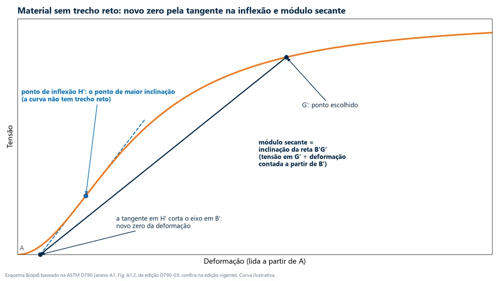
Toe compensation. The start of the curve is often curved because the bar seats on the supports, the loading nose indents the surface and gaps close up. This region, called the toe, is not a property of the material. The standard requires extending the straight portion down to zero load and using that point as the new zero for deflection, unless it can be shown that the curvature is a real response of the material. All strains are then measured from the new zero.
When the curve has no straight portion, the construction changes. The drawing below shows the one in Annex A1 of the standard: the tangent at the inflection point H′, where the slope is steepest, crosses the strain axis at B′, which becomes the zero point, and the modulus is the secant of the line from B′ to the chosen point G′. Note that the tangent crosses the curve at H′, because this is an inflection point and not the start of a straight portion.
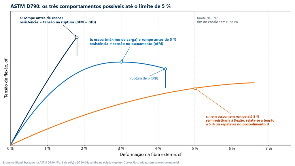
The 5% limit. The stress formula assumes a linear material and small strain. The standard accepts it for comparison and specification purposes up to 5% strain in the outer fiber. The test ends when the fiber reaches 0.05 mm/mm, at a deflection D = 0.05·L²/(6d), or earlier if the bar breaks. There are three possible behaviors:
- Break before 5%: the maximum load is the load at break, so flexural strength and stress at break are the same. This is typical of rigid plastics and many glass-fiber compounds.
- Yield before 5%: the load goes through a maximum, the yield point, and flexural strength is calculated from the load at that point.
- Neither break nor yield up to 5%: there is no flexural strength under D790. Report the stress at a given strain, for example at 5%, or repeat the test with Procedure B. These curves are read the same way as a stress-strain curve.
The graph below shows the three typical curves side by side, as in Figure 2 of the standard. Note where the load used to calculate strength falls: at break (a), at maximum load (b), or nowhere, when the curve crosses the 5% line without breaking or yielding (c).
Bars that break at an obvious flaw, such as a void or flash, are left out of the calculation and replaced with new bars. The result for each property is the arithmetic mean of the bars to three significant figures, with the standard deviation to two.
Correction for large deflections
With spans longer than 16:1, the bar can deflect a lot before it breaks. End forces develop at the supports and change the bending moment, and the simple formula underestimates the stress. When the span-to-depth ratio is greater than 16:1 and the deflection is more than 10% of the span, D790 requires the corrected equation:
σf = [3PL / (2bd²)] × [1 + 6(D/L)² − 4(d/L)(D/L)]
The first bracket is the simple formula. The second is an approximate correction factor for the effect of the end forces, and at typical deflections it is always slightly greater than 1. For the standard bar at 16:1, the deflection at 5% is 6.83 mm, about 13% of the span. Even so, the standard reserves the correction for spans longer than 16:1. Exercise 4 shows the difference for a laminate tested at 32:1.
Deflection measurement: crosshead or deflectometer
D790 allows two ways to measure deflection: from the movement of the loading nose relative to the supports, read at the crosshead, or with a deflectometer that touches the underside of the bar at midspan and is fixed relative to the supports. Manufacturers and laboratories often call them type 1 and type 2. The two give different results, so the report should state which one was used.
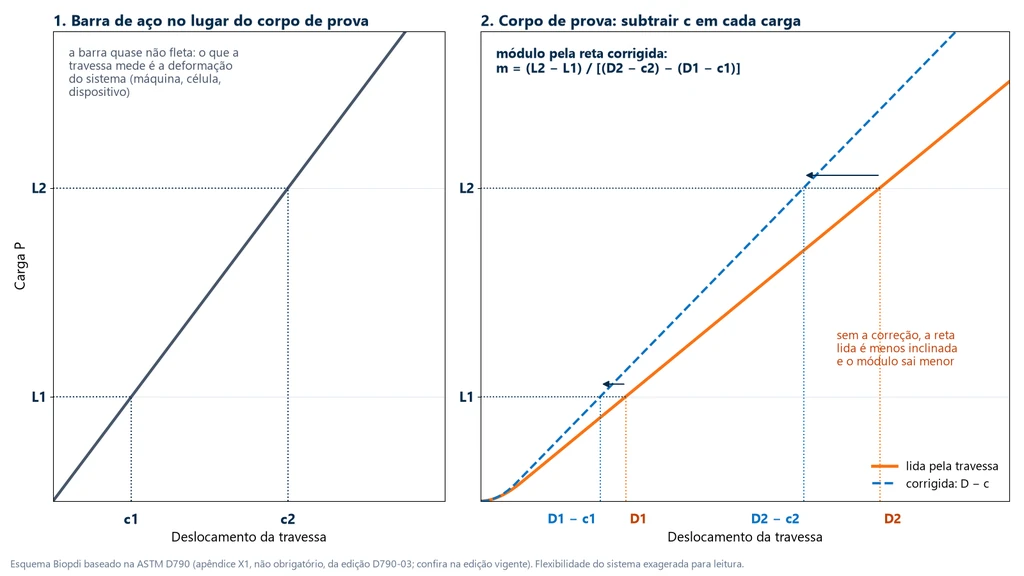
Crosshead displacement includes the elastic deformation of the system itself: frame, load cell, couplings and the fixture. The standard requires this deformation to stay below 1% of the total deflection of the bar, or to be corrected. The compliance correction subtracts the measured system deformation from the crosshead reading. Without it, the modulus comes out lower than the true value. Indentation of the loading nose in soft plastics has the same effect.
The diagram below shows the correction as described in the non-mandatory appendix X1 of the 2003 edition. With a steel bar in place of the test specimen, the load vs. crosshead displacement curve gives the system deformation, c1 and c2, at loads L1 and L2. These values are subtracted from the specimen readings D1 and D2 at the same loads, and the modulus is taken from the corrected line, which is steeper than the one read.
The verification requirements depend on the edition, and this is the point to check most carefully in D790-25:
- Force: in the 2003 edition, the machine is verified per ASTM E4, with a maximum error of ±1% of the maximum load expected in the test. Check the wording in the current edition. In Brazil, force verification follows ABNT NBR ISO 7500-1:2023 (the Brazilian adoption of ISO 7500-1), whose class 1 corresponds to an error of ±1%. This correspondence is this guide's interpretation, not text from D790.
- Crosshead and deflectometer: the 2003 edition does not set a class for deflection measurement. Later editions began to require verification of the crosshead per ASTM E2309 and of the deflectometer per ASTM E83. Secondary sources cite class B of E2309, classes B-2 and C of E83, and an effective gauge length of 50 mm for the deflectometer. These values have not been checked against the full text of D790-25.
In production quality control, the crosshead is usually enough. When the modulus is the number that matters, as in a datasheet or a dispute with a supplier, the deflectometer measures directly on the bar and eliminates system compliance.
ASTM D790, ISO 178 and ASTM D6272
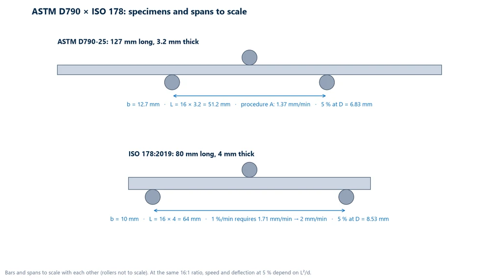
D790 states that it and ISO 178 address the same subject but differ in technical content. Both use three-point loading and a span of 16 times the thickness. What changes are the test specimen, the way the speed is set, the radii of the supports and, above all, the modulus. ISO 178 also reports the stress at the conventional deflection of 1.5 times the thickness, which corresponds to 3.5% strain. ISO 178:2019 is the sixth edition and replaced the 2010 edition, incorporating the 2013 amendment. The machine compliance correction already existed in the 2001 edition, in a normative annex.
The table compares the points that matter most in practice:
| Item | ASTM D790-25 | ISO 178:2019 |
|---|---|---|
| Preferred bar | 127 × 12.7 × 3.2 mm | 80 × 10 × 4 mm |
| Span | 16 d = 51.2 mm | 16 h = 64 mm |
| Radii | loading nose and supports of 5.0 mm | loading nose of 5.0 mm; supports of 2.0 mm (h ≤ 3 mm) or 5.0 mm |
| Speed | R = ZL²/6d, with 1%/min (A) or 10%/min (B) | 1%/min for the modulus, rounded to the standard's table (2 mm/min for the preferred bar) |
| Modulus | tangent to the straight portion (secant or chord, if specified) | chord between 0.05% and 0.25% strain |
| End of test | fracture or 5% | fracture or a predetermined value in the 2001 edition; stress also reported at the conventional deflection of 1.5 h (3.5%) |
The values in the ISO 178 column were checked against the text of the 2001 edition, with the 2004 amendment; verify them in the 2019 edition. ISO 178 also discards bars that break outside the middle third of the span and bars whose thickness is outside ±2% of the mean, and requires an error of no more than 1% in force and deflection.
Editions of ISO 178 after 2001 introduced their own test methods, described by secondary sources as method A, at 1%/min from start to finish, and method B, at 1%/min up to the modulus and faster afterward; this has not been checked against the full text of the 2019 edition. Do not confuse them with procedures A and B of D790, which mean something else. The drawing below compares the two bars and the two spans at the same scale: the ISO bar is shorter but thicker, and its span is longer.
Because of these differences, a D790 modulus and an ISO 178 modulus of the same material cannot be converted into one another. Resin datasheets often list both, each with its standard. When comparing suppliers, compare D790 with D790, under the same procedure, or ISO with ISO.
ASTM D6272-25 is the four-point flexural test standard for the same materials. The loading noses sit at one third or one half of the support span, and the bending moment is constant between them instead of concentrated under a single loading nose. D790 refers to it for materials that do not break within its strain limit; already in the 2003 edition, D790 covers only three-point loading.
Worked examples
The examples use the formulas from the previous sections. The numbers were recalculated by hand and rounded only in the final result.
Example 1: 6 mm sheet, span, width and speed
A 6.0 mm extruded sheet will be tested without machining the faces. What are the span, the maximum width, the minimum bar length and the speed in both procedures?
- Span: L = 16 × 6.0 = 96 mm.
- Width: since d > 3.2 mm, the width may not exceed L/4 = 24 mm. A 12.7 mm bar meets this.
- Length: the minimum overhang is the greater of 10% of the span (9.6 mm) and 6.4 mm, so the bar is at least 96 + 2 × 9.6 = 115.2 mm long.
- Procedure A: R = 0.01 × 96² / (6 × 6.0) = 92.16 / 36 = 2.56 mm/min, with a tolerance of ±10% (2.30 to 2.82 mm/min).
- Procedure B: R = 0.10 × 9,216 / 36 = 25.6 mm/min.
- Deflection at 5%: D = 0.05 × 9,216 / 36 = 12.8 mm.
The speed almost doubled compared with the 3.2 mm bar, because L² grows faster than d. Anyone who keeps 1.37 mm/min for every thickness is testing at a different strain rate.
Example 2: strength, strain and modulus with toe compensation
Bar of 127 × 12.7 × 3.2 mm (actual dimensions equal to nominal), span of 51.2 mm, procedure A at 1.37 mm/min, deflection from the crosshead with compliance correction. In the straight portion, the load went from 14.8 N at 0.60 mm to 51.8 N at 1.60 mm. The bar broke at 130 N with 4.30 mm read. The graph below shows this curve: the toe up to 0.6 mm, the line of slope m that crosses zero load at 0.20 mm, the fracture point and the 5% limit line.
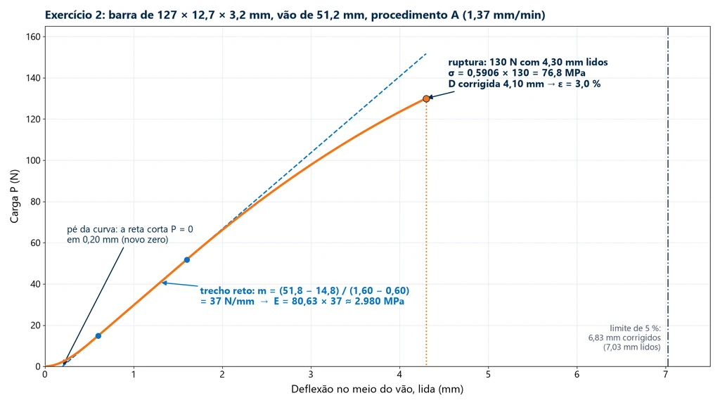
- Slope: m = (51.8 − 14.8) / (1.60 − 0.60) = 37 N/mm.
- Modulus: EB = 51.2³ × 37 / (4 × 12.7 × 3.2³) = 134,217.7 × 37 / 1,664.6 = 2,983 MPa ≈ 2.98 GPa.
- New zero: the line crosses zero load at 0.60 − 14.8/37 = 0.20 mm.
- Strain at break: corrected D = 4.30 − 0.20 = 4.10 mm; εf = 6 × 4.10 × 3.2 / 51.2² = 78.72 / 2,621.4 = 3.00%. Without compensation, it would be 3.15%.
- Strength: σf = 3 × 130 × 51.2 / (2 × 12.7 × 3.2²) = 19,968 / 260.10 = 76.8 MPa. Since it broke before 5%, the value is valid, and the stress at break is the same.
- 5% limit: D = 0.05 × 2,621.4 / 19.2 = 6.83 mm from the new zero, or 7.03 mm on the crosshead reading.
With 130 N at the peak, the right load cell is the smallest one on the machine, for example 2 kN, so the force stays within the verified range of the cell. The 10 kN flexural fixture has plenty of margin.
Example 3: material that does not break in procedure A
A standard polypropylene bar, in procedure A, reached 6.83 mm (5%) at 62 N, without breaking or showing a load maximum. Another bar from the same lot, in procedure B at 13.7 mm/min, passed through a maximum of 68 N at 5.9 mm of corrected deflection.
- Procedure A: there is no flexural strength. The stress at 5% is reported: σ = 0.5906 × 62 = 36.6 MPa.
- Procedure B: ε = 6 × 5.9 × 3.2 / 2,621.4 = 4.32%, below 5%, so the maximum is a valid yield. Strength: σ = 0.5906 × 68 = 40.2 MPa.
The two numbers are not comparable: the strain rate is ten times higher in B, and the report must state which procedure produced each value. The modulus of this material is still measured in procedure A.
Example 4: laminate at 32:1 with large deflection
A glass fiber laminate with b = 12.7 mm and d = 3.2 mm is tested at 32:1 (L = 102.4 mm) and breaks at P = 365 N and D = 13.6 mm.
- Criterion: D/L = 13.6 / 102.4 = 0.1328, above 0.10, with a span greater than 16:1. The correction applies.
- Simple formula: σ = 3 × 365 × 102.4 / (2 × 12.7 × 3.2²) = 112,128 / 260.10 = 431.1 MPa.
- Factor: 1 + 6 × 0.1328² − 4 × (3.2/102.4) × 0.1328 = 1 + 0.1058 − 0.0166 = 1.0892.
- Corrected strength: 431.1 × 1.0892 = 469.6 MPa, 8.9% above the simple formula.
- Strain: ε = 6 × 13.6 × 3.2 / 102.4² = 261.12 / 10,485.8 = 2.49%, below 5%.
Common mistakes when applying D790
The mistakes below show up frequently in reports and purchase specifications:
- Citing an old edition as current. The current one is D790-25; D790-00, -10 and -17 are superseded.
- Using a fixed span and speed. Both follow the measured thickness; if the thickness changes, the span and speed change.
- Reporting strength for a material that neither broke nor yielded by 5%. In that case, report the stress at a given strain, or switch to procedure B.
- Comparing a procedure A result with a procedure B result, or D790 with ISO 178, without a caveat.
- Modulus from the crosshead without compliance correction. The modulus comes out low.
- Skipping toe compensation. The strain at break comes out high, as in example 2.
- Using the simple formula with large deflections at spans above 16:1.
- Measuring thickness poorly. It enters squared in the stress and cubed in the modulus: a 1% error in d becomes about 2% in stress and 3% in modulus.
- Testing without conditioning. Humidity and temperature change the stiffness of many plastics.
- Leaving out parts of the report: procedure, crosshead speed, span and span-to-depth ratio, radii, cutting direction, modulus type and strains used, bar behavior (fracture or yield), mean and standard deviation of each property, and the method of measuring deflection.
Equipment for the ASTM D790 test
On the universal testing machine, D790 uses a flexural fixture with two supports of adjustable span and a loading nose attached to the crosshead. Forces are low: the standard bar breaks at tens to a few hundred newtons. For this reason, the single-column models from 2 to 10 kN, with speeds from 0.02 to 500 mm/min, cover the speeds of procedures A and B. The load cell of the M2 line has class 1 accuracy per ISO 7500-1:2023 (ABNT NBR ISO 7500-1 in Brazil). The BioLab software converts load vs. deflection into stress vs. strain and calculates strength, strain and modulus. The panel below shows the machine, the role of each part in the test and the fixtures used.
The universal testing machine in the ASTM D790 test
For plastics, the single-column model, from 2 to 10 kN, is the starting point. Each part of the machine has a function in the test:

- Moving crosshead lowers the loading nose at speed R = ZL²/6d
- Load cell small, class 1, for forces of tens of N
- Flexural fixture three-point, adjustable span for 16:1
- Deflectometer measures deflection under midspan
- BioLab software flexural strength, strain and modulus
- Control panel and emergency stop positions and stops the test
Fixtures for the flexural test
The fixtures below are mounted on the same machine, depending on the test specimen and the standard:
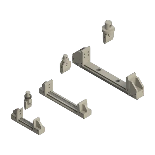
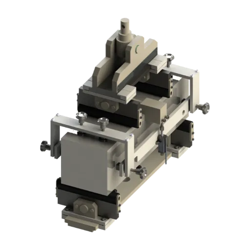
For D790, the 10 kN flexural fixture handles plastic and composite bars, and the deflectometer measures deflection directly on the bar when the modulus needs to be exact. To configure the machine, request a quote; other tests on the same machine are covered in mechanical tests.
Standards cited
The table lists the standards cited in this guide. Edition and status were checked on September 30, 2026 on the official pages (store.astm.org, and iso.org through distributors):
| Standard | Subject | Edition and status |
|---|---|---|
| ASTM D790 | three-point flexural testing of plastics and electrical insulating materials | D790-25, active |
| ISO 178 | flexural testing of plastics, three-point | 2019 (6th edition), current; new edition under development |
| ASTM D6272 | four-point flexural testing of plastics | D6272-25, active |
| ASTM D638 | tensile testing of plastics | D638-22, active |
| ASTM D618 | conditioning of plastics | D618-21, active |
| ASTM E4 | force verification of testing machines | E4-24, active |
| ASTM E2309 | verification of displacement measuring systems | E2309/E2309M-20, active |
| ASTM E83 | verification and classification of extensometers | E83-25, active |
| ABNT NBR ISO 7500-1 (Brazilian adoption of ISO 7500-1) | verification of the testing machine force-measuring system | 2023 |
Other tests and technical references
Tests performed on the Biopdi universal testing machine



















Related technical references
ASTM D695: compression testing of rigid plastics (test specimen, 1.3 mm/min and calculations)
ASTM D695-26 measures compressive strength, yield and modulus of rigid plastics: a 12.7 × 12.7 × 25.4 mm prism at 1.3 mm/min. Calculations and ISO 604.
Flexural test: 3-point and 4-point bending, how to calculate flexural strength, and standards
In a flexural test, a bar supported at two points is loaded until it fails. Learn 3- and 4-point setups, flexural strength and modulus formulas, NBR 12142 and ASTM D790.
Crush test: ECT, FCT, RCT and BCT
The crush test compresses corrugated board until it collapses. See ECT, FCT, RCT, CMT and BCT, formulas, McKee, 32 ECT in kN/m, standards and examples.
Frequently asked questions
What is ASTM D790?
It is the ASTM standard for three-point flexural testing of unreinforced and reinforced plastics and electrical insulating materials. A simply supported bar is loaded at mid-span, and the test measures flexural strength, flexural strain and flexural modulus. The current edition is D790-25.
What is the difference between ASTM D790 and ASTM D638?
D638 is the tensile test for plastics, with a dumbbell-shaped (dog-bone) test specimen held in grips. D790 is the flexural test, with a bar that simply rests on supports. The properties from one do not replace those from the other.
What is the difference between Procedures A and B of D790?
Procedure A uses a strain rate of 0.01 mm/mm/min (1%/min), is the preferred procedure and is the one to use for the modulus. Procedure B uses 0.10 mm/mm/min (10%/min), is intended for material that does not break or yield by 5% strain under Procedure A, and gives only the strength; the modulus comes from Procedure A. Results from the two procedures are not comparable.
What is the test speed in ASTM D790?
It is calculated as R = ZL²/(6d). For the 3.2 mm bar with a 51.2 mm span, it gives 1.37 mm/min in Procedure A and 13.7 mm/min in Procedure B, with a tolerance of ±10%. For a 6 mm sheet at 16:1, it rises to 2.56 mm/min in Procedure A.
What is the D790 specimen size?
The preferred specimen for molding materials is 127 × 12.7 × 3.2 mm, tested with a span of 16 times the thickness, 51.2 mm. Thicker sheets use a width of up to one quarter of the span, and sheets thinner than 1.6 mm use a 50.8 × 12.7 mm bar with a 25.4 mm span.
Why does the D790 test stop at 5% strain?
Because the beam formula used in the calculation assumes small strains and is only accepted up to 5% in the outer fiber. If the material does not break or yield by that point, the standard does not allow flexural strength to be reported; the stress at a given strain is reported instead.
How is the flexural modulus calculated in D790?
From the tangent modulus, E = L³m/(4bd³), where m is the slope of the initial straight portion of the load-deflection curve. For the standard bar, E ≈ 80.6 × m, with m in N/mm and E in MPa. The standard also provides for secant and chord moduli.
When should the large-deflection correction be used?
When the span-to-depth ratio exceeds 16:1 and the deflection exceeds 10% of the span. In that case, the simple stress is multiplied by [1 + 6(D/L)² − 4(d/L)(D/L)], which for a laminate at 32:1 can add close to 9%.
Does ASTM D790 include a four-point test?
No. D790 covers three-point flexure only. Four-point flexural testing of plastics is in ASTM D6272-25, recommended for materials that do not break within the D790 limit.
Do ASTM D790 and ISO 178 give the same result?
Not necessarily. ISO 178:2019 uses an 80 × 10 × 4 mm bar, a 64 mm span, 2 mm/min and a chord modulus between 0.05% and 0.25% strain (values checked against the 2001 edition); D790 uses the 127 mm bar and the tangent modulus. The values cannot be converted from one to the other.
Does the D790 test require a deflectometer?
It is not mandatory. Deflection can be taken from the crosshead, provided the system compliance does not exceed 1% of the bar deflection or is corrected for. A deflectometer measures directly under the bar and gives a more accurate modulus; the method used should be recorded in the report.