
The Rockwell hardness test measures a metal's resistance to indentation from the permanent depth h left by a diamond or ball indenter after a total force of 60, 100 or 150 kgf (588.4, 980.7 or 1,471 N), and turns that depth into a number with HR = N − h/S: the shallower the indentation, the harder the material. On the C scale, used for hardened steels, N = 100 and S = 0.002 mm, so a permanent depth of 0.082 mm gives 100 − 41 = 59 HRC. The method is defined by ISO 6508-1:2023, adopted in Brazil as ABNT NBR ISO 6508-1:2025, and by ASTM E18-25.
The Rockwell hardness test is fast, the hardness tester shows the result directly on its display and the indentation is small, which is why it dominates heat treatment control and incoming inspection. But it measures only one variable: the surface's resistance to localized indentation. Yield strength, elongation, modulus of elasticity and toughness are not covered, and that is why, to approve a material, hardness is complemented by universal testing machine tests and by impact testing, as shown in the dedicated section further below. The comparison of all hardness methods (Brinell, Vickers, Shore, portable) is in the article on hardness testing; here the subject is the Rockwell method in depth.
How the Rockwell test works: preliminary force, total force and permanent depth
The test applies the force in two levels. First comes the preliminary force F0, 98.07 N (22.05 lbf) on the regular scales or 29.42 N (6.614 lbf) on the superficial scales. It seats the indenter, gets through fine roughness, the oxide film and the clearances in the support, and defines the reference plane: the instrument zeroes the depth measurement at that point. Everything above it, including surface irregularities, stays out of the reading.
Next the additional force F1 is applied, which many texts call the major load (the values of 60, 100 and 150 kgf quoted for it are, in fact, those of the total force). The sum F = F0 + F1 is the total force of the scale: 1,471 N (330.7 lbf) for HRC, for example. Under the total force the indenter reaches its maximum depth, with an elastic and a plastic portion of deformation. Then F1 is removed and the force returns to the preliminary force. The elastic part recovers (the material "gives back" part of the penetration, as explained in elastic deformation), and what remains is the plastic deformation: the permanent depth h, measured from the reference plane and still under F0.
Hardness is calculated with the general formula of ISO 6508-1:
HR = N − h/S
- N is the full-scale value: 100 on the regular diamond scales (A, C, D) and on all superficial scales; 130 on the regular ball scales (B, E, F, G, H, K).
- S is the depth corresponding to one Rockwell unit: 0.002 mm on the regular scales and 0.001 mm on the superficial scales.
- h is the permanent depth, in millimeters. The inverse, h = S × (N − HR), is the one used to check minimum thickness, as shown below.
The subtraction makes the scale "run backwards" relative to depth: a deep indentation gives a small number, a shallow indentation gives a large number, so a harder material gets a higher number, as on the other hardness scales. The N = 130 of the ball scales exists because, in soft material, the ball penetrates more than 0.200 mm; with N = 100 those readings would be negative. The chart below shows the three lines and three typical readings: 60 HRC, 75 HRBW and 90 HR15N correspond to depths of 0.080, 0.110 and 0.010 mm, which is why equal numbers on different scales do not mean the same thing.
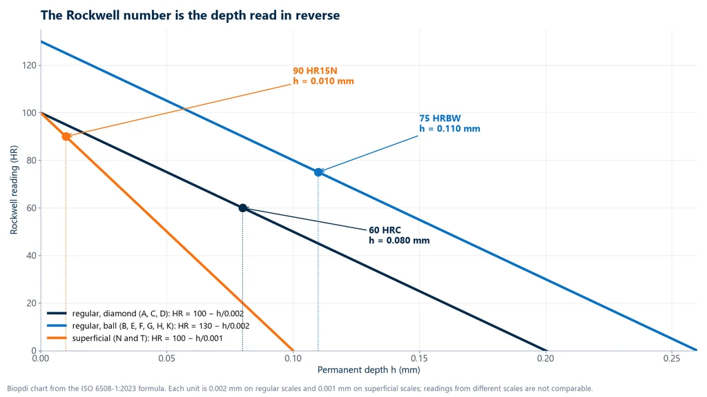
The complete cycle, with force and depth as a function of time, is drawn in the article on hardness testing. What matters here is the consequence of the formula: on the C scale, each HRC point is worth 2 µm of depth, and on the superficial scales, 1 µm.
Advantages and limitations of the Rockwell method
The core advantage of Rockwell is that it measures depth, not indentation size. Brinell, Vickers and Knoop measure the indentation under a microscope after the force is removed; Rockwell is the only standardized bench method that reads depth, with a displacement sensor in the hardness tester itself. This gives the practical advantages:
- Direct reading, with no optical measurement and little operator dependence.
- Short cycle, under 20 s, allowing large batches to be measured on the production line.
- Simpler hardness tester, without the optical measuring system of the Brinell and Vickers methods.
- Light preparation: on the regular scales, a clean, smooth surface is usually enough, with no mounting or metallographic polishing.
- Small mark: the part usually stays in service, which is why Rockwell is treated as an almost non-destructive test, as discussed in destructive and non-destructive testing.
The price is sensitivity. Since 1 HRC equals 2 µm, any movement other than the indentation enters the reading: a particle between the part and the anvil, an anvil that deflects, a part that rotates on its support, floor vibration. These displacements add depth and therefore lower the number. The preliminary force eliminates the clearances present at the start of the test, but not those that appear while F1 is applied. That is why Rockwell requires a rigid, clean support, more than the optical methods do.
There are three other limitations. The scales are not related to each other by a formula, so an HRC reading cannot be compared with an HRBW reading without a conversion table. A chipped or worn diamond indenter changes the reading without the operator noticing, which is why only certified indenters are used. And, at the top of the C scale, the depth becomes so small that very hard materials are poorly differentiated; for cemented carbide and thin layers, the A scale, the superficial scales or Vickers discriminate better.
In industry, Rockwell is the test for controlling quenching and tempering, for incoming inspection, for comparing suppliers and for failure analysis. It is also the reading method of the Jominy hardenability test, in which HRC is measured along a bar quenched at one end.
Rockwell indenters and scales
Each Rockwell scale is a fixed combination of indenter and total force, identified by a letter (regular scales) or by a number and a letter (superficial scales). There is no such thing as "the Rockwell hardness" of a material without the scale, just as there is no length measurement without a unit.
The indenters
ISO 6508-1:2023 allows two types of indenter:
- Spheroconical diamond: a diamond cone with a 120° included angle and a rounded tip with a 0.2 mm radius. It is used on hard material because it does not deform. Each indenter is certified for regular scales, superficial scales or both.
- Cemented carbide ball (tungsten carbide) of 1.5875 mm (1/16") or 3.175 mm (1/8"). It is used on soft material, where the cone would sink too deep. The letter W in the symbol, as in HRBW, indicates the cemented carbide ball.
The steel ball, which appears in older teaching material, has been dropped from the general method: today it is only allowed in the special test for very thin sheet, HR30TSm and HR15TSm, described in an annex of the standard. ASTM E18 also has scales with 6.350 and 12.70 mm balls (L, M, P, R, S and V) for very soft materials, which ISO accepts by agreement between the parties. Combining the 5 indenters (diamond and 1/16", 1/8", 1/4" and 1/2" balls) with the 6 total forces (15, 30, 45, 60, 100 and 150 kgf), ASTM E18 reaches 30 scales.
Regular scales
On the regular scales the preliminary force is always 98.07 N. The table lists the nine scales of ISO 6508-1, with the total force, the range in which the result is valid and the typical use. Outside the application range the result is not accepted: the correct approach is to change scale.
| Scale | Indenter | Total force | Range and typical use |
|---|---|---|---|
| HRA | Diamond (N = 100) | 588.4 N (132.3 lbf) | 20 to 95 HRA; cemented carbide, thin steel, shallow carburized case |
| HRBW | 1.5875 mm ball (N = 130) | 980.7 N (220.5 lbf) | 10 to 100 HRBW; copper alloys, mild steel, aluminum alloys |
| HRC | Diamond (N = 100) | 1,471 N (330.7 lbf) | 20 to 70 HRC; hardened steel, hard cast iron, titanium |
| HRD | Diamond (N = 100) | 980.7 N (220.5 lbf) | 40 to 77 HRD; thin steel, medium carburized case |
| HREW | 3.175 mm ball (N = 130) | 980.7 N (220.5 lbf) | 70 to 100 HREW; cast iron, aluminum and magnesium alloys |
| HRFW | 1.5875 mm ball (N = 130) | 588.4 N (132.3 lbf) | 60 to 100 HRFW; annealed copper, thin soft sheet |
| HRGW | 1.5875 mm ball (N = 130) | 1,471 N (330.7 lbf) | 30 to 94 HRGW; phosphor bronze, beryllium copper, malleable iron |
| HRHW | 3.175 mm ball (N = 130) | 588.4 N (132.3 lbf) | 80 to 100 HRHW; aluminum, zinc, lead |
| HRKW | 3.175 mm ball (N = 130) | 1,471 N (330.7 lbf) | 40 to 100 HRKW; bearing metals and other very soft metals |
The ranges have a physical reason. Below 20 HRC, the cone sinks so deep that the tip geometry no longer controls the indentation and the scale loses resolution; the standard calls for switching to HRBW. Above 100 HRBW, the ball barely penetrates and starts to flatten; the switch is to HRC. The HRC and HRBW scales cover most steels; the others exist for materials and thicknesses those two cannot handle.
Superficial N and T scales
The superficial scales use a preliminary force of 29.42 N, total forces of 147.1, 294.2 or 441.3 N (33.07, 66.14 or 99.21 lbf) and S = 0.001 mm. The number in the scale name is the total force in kgf; the letter indicates the indenter: N for the diamond, T for the 1.5875 mm ball. With lower forces the indentation is shallow, suitable for thin sheet, small parts and shallow hardened layers.
| Scale | Indenter | Total force | Application range |
|---|---|---|---|
| HR15N | Diamond | 147.1 N (33.07 lbf) | 70 to 94 HR15N |
| HR30N | Diamond | 294.2 N (66.14 lbf) | 42 to 86 HR30N |
| HR45N | Diamond | 441.3 N (99.21 lbf) | 20 to 77 HR45N |
| HR15TW | 1.5875 mm ball | 147.1 N (33.07 lbf) | 67 to 93 HR15TW |
| HR30TW | 1.5875 mm ball | 294.2 N (66.14 lbf) | 29 to 82 HR30TW |
| HR45TW | 1.5875 mm ball | 441.3 N (99.21 lbf) | 10 to 72 HR45TW |
On the N scale, typical uses are thin carburized or nitrided cases and hardened steel sheet; on the T scale, thin sheet of low-carbon steel, brass or aluminum.
How to write the result
The notation is the value, followed by HR, the scale letter or code, and W when the indenter is a cemented carbide ball: 59 HRC, 75 HRBW, 77 HR30N, 70 HR30TW. When the total force has to be held longer than normal because the material keeps sinking, the dwell time enters the notation, as in 65 HRFW/10 s. On a convex part, the curvature correction applied is reported with the result.
How to choose the Rockwell scale
The Rockwell scale is chosen by three criteria, in this order: the expected hardness, the part thickness and the application range of the scale. Each criterion becomes a question:
- What is the expected hardness? Hard material (hardened steel, white cast iron, cemented carbide) calls for diamond; soft material (annealed steel, brass, aluminum) calls for a ball.
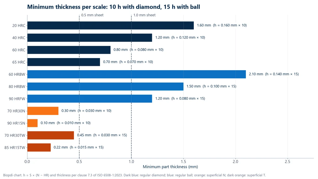
- What is the thickness of the part, or of the layer of interest? The part must be at least 10 times the permanent depth with diamond and 15 times with a ball. If it is not, move to a lower force or to a superficial scale.
- Does the reading fall within the application range? If not, change scale, even if the thickness allows it.
The larger factor for the ball has a geometric explanation: for the same depth, a ball's cap is wider than the cone's and deforms a larger volume of material beneath it. Since depth depends on the reading, so does minimum thickness: in the same steel, the softer it is, the thicker the part needs to be. The chart below calculates this thickness for common readings on several scales, with h = S × (N − HR), and marks 0.5 and 1.0 mm sheets. It shows that a 1.0 mm sheet does not allow HRC below 50, nor any usual HRBW reading, but comfortably allows the superficial scales.
In practice, the drawing specification usually already sets the scale: a shaft specified "55 to 60 HRC" is checked in HRC. When it does not, the table summarizes the usual choice by part type:
| Part | Usual scale | Why |
|---|---|---|
| Quenched and tempered steel shaft, about 55 HRC | HRC, with V-block and curvature correction | Diamond for hard material; convex surface requires correction |
| Annealed or rolled steel part | HRBW | Soft material, within 10 to 100 HRBW |
| Annealed brass bushing | HRBW or HRFW | Ball; F, with lower force, for very soft or thin material |
| 0.6 mm low-carbon steel sheet | HR30TW or HR15TW | Thin, soft sheet: superficial scale with ball |
| Shallow nitrided case | HR15N, or low-force Vickers | Low force limits penetration to the case |
| Gray cast iron | HREW, but preferably Brinell | Heterogeneous structure calls for a large indentation |
The case-hardened layer deserves care: an HRC reading on a carburized part mixes the case and the core, because the deformation beneath the indentation reaches several times h. To know the hardness through the depth, the approach is a microhardness profile on a polished cross-section, described in the article on carburizing.
Procedure under ISO 6508-1:2023 and ASTM E18-25
A valid Rockwell test under ISO 6508-1:2023 and ASTM E18-25 requires a clean surface, rigid and perpendicular support, a force cycle with defined times, minimum thickness and spacing, and a hardness tester verified on the day of testing. The summarized step by step is in the article on hardness testing; here each requirement comes with its reason, because the reason is what lets you recognize a test performed outside the standard. ISO 6508-1 and ASTM E18 describe the same test, with minor differences in times and tolerances; when the customer or the specification does not state which one applies, the laboratory declares which standard it followed.
Surface and support
The surface must be smooth, flat, free of scale, foreign matter and lubricant. The exception is reactive metals such as titanium, where a lubricant such as kerosene may be used, provided it is reported. Preparation must not heat or work harden the surface: dry grinding tempers the surface layer of a quenched steel and lowers the reading; coarse grinding work hardens it and raises the reading. A decarburized layer is removed first, unless it is the object of the test.
The part rests on a rigid support, with the surface perpendicular to the indenter axis. A cylindrical part goes on a V-block or a twin cylinder anvil, with a hardness of at least 60 HRC, so that the support does not sink along with it. The test is performed between 10 °C and 35 °C; outside this range, the temperature goes into the report.
The required finish depends on the force. The regular scales tolerate a ground surface; on the 15 kgf superficial scales, where each point equals 1 µm, a polished or lapped surface is recommended, prepared without work hardening. For parts that do not seat well, there are specific anvils: the spot anvil, with a small raised flat area, for small parts or parts with an irregular underside, and the diamond spot anvil, for thin sheet on the 15T and 30T scales, never used with a diamond indenter. Perpendicularity also matters: according to Buehler, a hardness tester manufacturer, a 1° tilt between the surface and the indenter axis can change the HRC reading by about 5%.
Force cycle and times
The preliminary force is applied without shock, within 2 s, and held for 3 s (1 to 4 s). The additional force is applied in 1 to 8 s on the regular scales and within 4 s on the superficial scales. The total force is held for 5 s (2 to 6 s), and the reading is taken 4 s (1 to 5 s) after F1 is removed, still under the preliminary force.
The times exist because the metal keeps flowing while the force acts. A total force held longer makes the indentation deeper and the reading lower; an application that is too fast, with impact, also deepens it. In materials that creep significantly under load, such as soft alloys, the difference between a short and a long cycle can exceed one point on the scale, which is why a non-standard time must appear in the designation.
Thickness and spacing
The minimum thickness is 10 times h for the diamond and 15 times h for the ball, unless it is shown that a thinner part gives the same result; the charts in Annex B of the standard give the values. After the test, no mark may appear on the back. A part that is too thin lets the anvil support the indentation, and the reading comes out high: this is known as the anvil effect.
The minimum distance between the centers of two indentations is 3 indentation diameters; from the center to the edge, 2.5 diameters (ISO 6508-1:2023, clause 8.13). Near the edge there is not enough material to contain the deformation, and the reading drops. Near another indentation, the indenter meets the zone the first one work hardened, and the reading rises. Older editions and teaching material give 4 diameters between centers; the rule in the current edition is 3.
Curved surfaces
On a convex surface, such as a shaft, there is less lateral material to support the indenter, the indentation goes deeper and the reading is lower than on a flat surface of the same material. The standard provides correction tables for cylinders (Annex C) and spheres (Annex D), as a function of the diameter and the reading; the correction is added to the measured value and stated in the report. Corrections greater than 3 points on the A, C and D scales, or 5 points on the B, F and G scales, are not accepted: the diameter is too small for that scale. Concave surfaces are tested only by agreement, with no table.
Hardness tester verification
Daily verification is performed before the first test of the day, on each scale to be used, with a reference block: a homogeneous block of steel or another metal with a certified hardness. If the reading falls outside the certificate tolerance, the tester is not used until the cause is found. After changing the indenter or the anvil, at least two tests are made and discarded to seat the parts, and the daily verification is repeated.
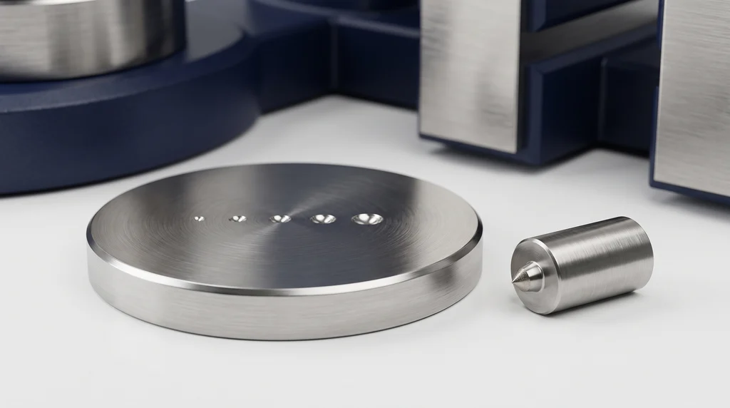
The photo shows a hardness reference block with a row of indentations and, next to it, the conical indenter: Rockwell indentations are small because the method reads depth, and the reference block is used to check that the hardness tester indicates the correct value.
Besides the daily check, there is indirect verification, with blocks in several ranges, and direct verification, which calibrates the force, the indenter, the depth measuring system and the cycle. Both follow ISO 6508-2:2023; calibration of reference blocks follows ISO 6508-3:2023. In practice, indirect verification by an accredited laboratory is usually done once a year, or more often under heavy use, according to Buehler. Portable hardness testers that perform Rockwell by indentation have their own standard, ASTM E110.
The report
The report includes the standard, with its edition; the identification of the part and of the tested surface, including the diameter if it is curved; the result in full notation; the individual readings; the corrections applied; the temperature, if outside 10 °C to 35 °C; and any occurrence that may have affected the result. The number of readings per part comes from the specification; in its absence, the usual practice is at least three, with mean and scatter.
Worked examples
The three examples use the formula HR = N − h/S and its inverse, h = S × (N − HR), to decide whether a test is valid. The calculations are complete so they can be repeated.
1. Hardness of a shaft and indentation spacing. On a 30 mm diameter quenched steel shaft, the hardness tester recorded, on the C scale, a permanent depth h = 0.082 mm. The C scale has N = 100 and S = 0.002 mm, so h/S = 0.082 / 0.002 = 41 and HRC = 100 − 41 = 59 HRC, within the 20 to 70 HRC range. The minimum thickness would be 10 × 0.082 = 0.82 mm, irrelevant for a solid shaft. Since the surface is convex, the reading is corrected using the Annex C table for 30 mm cylinders, and the correction value goes into the report. If the diameter of each indentation, measured under the microscope, is 0.60 mm, the next indentation must be at least 3 × 0.60 = 1.80 mm center to center, and none may be closer than 2.5 × 0.60 = 1.50 mm to an edge, such as a shoulder or a hole.
2. What reading validates the test on a 1.0 mm brass sheet? With a ball, the thickness must be at least 15 h, so the maximum h = 1.0 / 15 = 0.0667 mm. On the regular ball scales (N = 130, S = 0.002 mm), this requires a reading of at least 130 − 0.0667/0.002 = 130 − 33.3 = 96.7, in HRBW or HRFW. A brass reading 75 HRBW had h = 0.002 × (130 − 75) = 0.110 mm and would require 15 × 0.110 = 1.65 mm of sheet: the test is not valid. On the superficial ball scales (N = 100, S = 0.001 mm), the limit is 100 − 0.0667/0.001 = 100 − 66.7 = 33.3, in HR30TW or HR15TW. Any reading above that validates the test, and almost the entire HR30TW range (29 to 82) qualifies. The check is always made with the reading obtained: measure, calculate h and compare 15 h with the actual thickness.
3. A 0.5 mm hardened sheet at about 60 HRC. On the C scale, h = 0.002 × (100 − 60) = 0.080 mm and the minimum thickness is 10 × 0.080 = 0.80 mm, greater than 0.5 mm: the HRC test is not valid, and the reading would come out high because of the anvil effect. For 0.5 mm, the maximum h with a diamond is 0.5 / 10 = 0.050 mm. On the N scales (N = 100, S = 0.001 mm), this requires a reading of at least 100 − 50 = 50. According to the ASTM E140 conversion table, 60 HRC corresponds to about 90.2 HR15N, 77.5 HR30N and 66.6 HR45N. On HR45N, h = 0.001 × (100 − 66.6) = 0.0334 mm and the minimum thickness is 10 × 0.0334 = 0.33 mm; on HR30N, 0.0225 mm and 0.23 mm; on HR15N, 0.010 mm and 0.10 mm. All three work. HR45N, the highest force that still respects the thickness, is the least sensitive to surface finish. The value measured in HR45N is reported as such; converted to HRC, it is only an estimate.
Rockwell vs Brinell vs Vickers: differences and HRC to HB conversion
The difference between the Rockwell and Brinell hardness tests lies in what is measured: Rockwell measures the permanent depth of the indentation and gives a direct reading on the hardness tester; Brinell measures the diameter of a large indentation, made by a tungsten carbide ball up to 10 mm, and divides the force by the area. Vickers follows the Brinell logic with a diamond pyramid and measures the diagonals of the indentation. The table summarizes what changes in practice:
| Criterion | Rockwell | Brinell | Vickers |
|---|---|---|---|
| Quantity measured | Permanent depth | Indentation diameter (area) | Indentation diagonals (area) |
| Indenter | Diamond cone or tungsten carbide ball | Tungsten carbide ball, 1 to 10 mm | 136° diamond pyramid |
| Reading | Direct on the hardness tester | Optical | Optical |
| Indentation size | Small | Large, averaging coarse structures | Small to microscopic |
| Standard | ISO 6508-1:2023 and ASTM E18-25 | ISO 6506-1:2014 and ASTM E10-23 | ISO 6507-1:2023 and ASTM E92-26 |
| Typical use | Hardened steel, production control | Castings, forgings, heterogeneous material | Laboratory, case layers, microhardness |
HRC and HB are not two units of the same quantity. HB is force divided by the area of the spherical cap (in kgf/mm², written without a unit), and HRC is a number derived from a depth. Converting one to the other is only possible with an empirical table, built from comparative tests for each family of materials: ISO 18265:2013 and ASTM E140. For non-austenitic steels, some points from the ASTM E140 table are:
| HRC | HV | HB (10 mm ball, 3,000 kgf) |
|---|---|---|
| 60 | 697 | 654 |
| 50 | 513 | 481 |
| 40 | 392 | 371 |
| 32 | 318 | 301 |
| 20 | 238 | 226 |
So 300 HB in a steel corresponds to about 32 HRC. The complete table, with the estimated tensile strength, is in the article on hardness of materials, and the method for each test is in the articles on Brinell hardness and Vickers hardness and microhardness. A converted value is always identified as converted and does not replace a measurement on the specified scale.
What hardness does not measure: why you need a universal testing machine as well
The hardness test measures one variable: resistance to localized indentation at the surface, under quasi-static force, over a region a few tenths of a millimeter across. It does not measure yield strength, elongation, reduction of area, modulus of elasticity or toughness. To approve a material against a specification, hardness is complemented by the tests performed on a universal testing machine (tensile, compression, flexural and bend tests) and by the impact test.
ASTM E18 itself describes Rockwell as an empirical test that provides useful information and that may correlate with tensile strength, wear resistance and ductility. The verb is "correlate", not "measure". ISO 6508-1:2023 goes further: it states that there is no general process for converting Rockwell hardness into tensile strength and that such conversion should be avoided unless it is based on comparative tests.
The same applies to wear: higher hardness usually increases abrasion resistance, but a hard material with low toughness can fail by cracking or chipping before it wears, and the Rockwell number does not show that.
The table shows, property by property, what the Rockwell reading tells you and which test actually measures each one:
| Property | Does hardness tell you? | Test that measures it | Equipment |
|---|---|---|---|
| Resistance to surface indentation | Yes: this is what it measures | Hardness (Rockwell, Brinell, Vickers) | Hardness tester |
| Yield strength (ReH, Rp0.2) | No | Tensile | Universal testing machine with extensometer |
| Ultimate tensile strength (Rm) | Only an estimate from a table | Tensile | Universal testing machine |
| Elongation after fracture (ductility) | No | Tensile | Universal testing machine with extensometer |
| Reduction of area | No | Tensile | Universal testing machine |
| Modulus of elasticity | No | Tensile with extensometer | Universal testing machine with extensometer |
| Compressive strength | No | Compression | Universal testing machine or press, with compression platens |
| Flexural strength and modulus | No | 3-point or 4-point flexural | Universal testing machine with flexural fixture |
| Bend ductility | No | Bend | Universal testing machine with bend fixture |
| Impact toughness | No | Charpy or Izod impact | Pendulum impact tester |
The physical reason is simple. A Rockwell indentation plastically deforms a small volume, already heavily work hardened by the indentation itself, and the reading sums up that state in a single number. The stress-strain curve of a whole test specimen, obtained in the tensile test, shows where the material starts to yield, how much it work hardens, how much it elongates before necking and how much elastic stiffness it has. None of that fits into a depth of 0.08 mm.
The correlation with strength: an estimate, not a measurement
In steels, hardness and ultimate tensile strength go together, because both reflect resistance to plastic flow. Callister's rule of thumb for most steels is Rm (MPa) ≈ 3.45 × HB, and the tables in ISO 18265:2013 and ASTM E140 convert between scales and give an estimated strength. These tables, the same ones used for the HRC to HB conversion in the previous section, also include a column of estimated tensile strength.
Three limits always apply. A table is only valid for the material family it was made for: the table for non-austenitic steel does not work for austenitic stainless steel, brass or cast iron. ISO 18265 rates the tensile strength estimate as the least reliable of its conversions. And even when it gets Rm right, the conversion says nothing about yield, elongation or toughness, which are precisely the numbers that usually cause a material to be rejected. The two examples below show this with numbers.
Example 1: two cast irons at 170 HB
Consider two castings that both read 170 HB, a value within the typical hardness range of both. One is ASTM A48 class 30 gray cast iron, whose class guarantees a minimum strength of 30 ksi, or 207 MPa, with elongation below 1%. The other is ASTM A536 60-40-18 ductile iron, whose name gives the minimums in ksi: tensile strength of 60 ksi (414 MPa), yield of 40 ksi (276 MPa) and elongation of 18%.
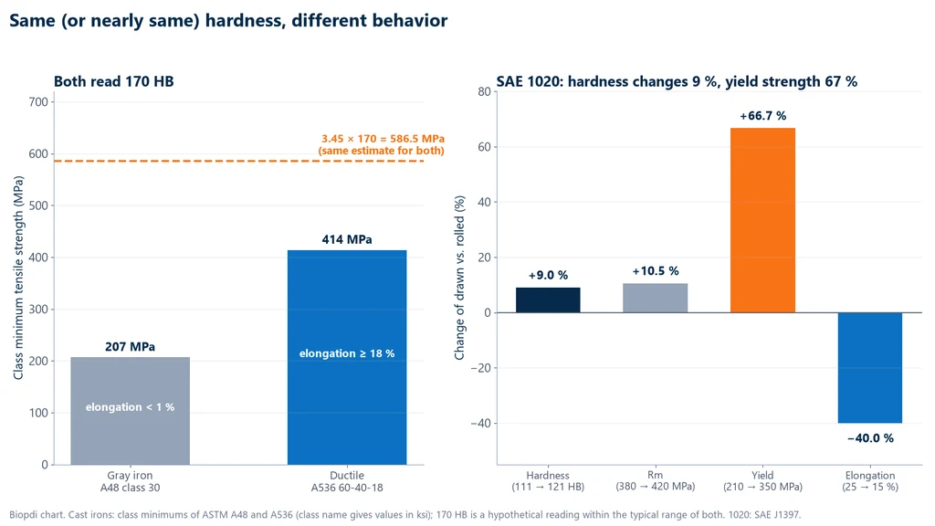
The 3.45 × HB rule would give 3.45 × 170 = 586.5 MPa for both. For the gray iron, the estimate is 586.5 / 207 = 2.8 times the class minimum; for the ductile iron, 1.4 times. The difference between the two materials comes from the shape of the graphite: in gray iron it forms flakes, which concentrate stress and open cracks; in ductile iron it forms spheres, which hardly concentrate stress at all. The Rockwell or Brinell indenter, resting on a region of metallic matrix, cannot see that difference. The chart below puts this case side by side with example 2, which follows: the dashed orange line is the same estimate for two materials that behave in opposite ways.
Only the tensile test tells the two castings apart. In a hypothetical test specimen with a 10 mm gauge diameter, with an area of π × 10² / 4 = 78.54 mm², the minimum breaking force would be 207 × 78.54 = 16.3 kN for the gray iron and 414 × 78.54 = 32.5 kN for the ductile iron. For the ductile iron, the extensometer also shows the yield point and the 18% elongation; for the gray iron, the curve ends with almost no plastic deformation.
Example 2: hot-rolled and cold-drawn SAE 1020 steel
The second case involves a single steel. According to SAE J1397, hot-rolled 1020 has a hardness of about 111 HB, Rm of 380 MPa, yield strength of 210 MPa and elongation of 25%; cold-drawn 1020 has about 121 HB, 420 MPa, 350 MPa and 15%. In the cold-drawn bar, cold deformation through the die work hardened the material.
Hardness rose by (121 − 111) / 111 = 9.0% and Rm rose by (420 − 380) / 380 = 10.5%: here the 3.45 × HB rule actually works, with 3.45 × 111 = 383 MPa and 3.45 × 121 = 417 MPa. But yield strength rose by (350 − 210) / 210 = 66.7% and elongation dropped by (25 − 15) / 25 = 40%. The yield-to-tensile ratio went from 210 / 380 = 0.55 to 350 / 420 = 0.83: the cold-drawn steel has much less margin between the onset of yielding and fracture. A specification requiring a minimum yield strength of 300 MPa approves one and rejects the other, and the hardness reading, which changed by 10 HB, does not reveal it. The tensile test, with an extensometer, does.
Using the same calculation as in example 1, a 10 mm diameter test specimen of cold-drawn 1020 breaks at about 420 × 78.54 = 33.0 kN, a force well within the range of a 50 kN universal testing machine.
Example 3: normal hardness, low toughness
The third case has no exact figures, but it is well known in the metallurgy of quenched steels. In steels such as SAE 4340, tempering in an intermediate temperature range, around 300 °C, causes tempered martensite embrittlement: the energy absorbed in the Charpy test drops into a trough, while hardness keeps decreasing smoothly and continuously with tempering temperature (Materkowski and Krauss, Metallurgical Transactions A, 1979). Two parts of the same steel, tempered at different temperatures and with similar hardness, can have very different impact energies. Studies on the subject report that this embrittlement shows up in the impact test and does not show up in the room-temperature tensile test: not even the tensile test replaces the Charpy test, let alone hardness.
The test plan that hardness does not replace
When qualifying a material or a heat treatment, Rockwell plays the role of screening and process control: it confirms whether the quench took, whether the lot is uniform, whether the part is within the drawing range. The complete plan usually includes these steps:
- Rockwell hardness on every part or on a sample of the lot, for screening.
- Tensile test on the universal testing machine: yield strength, ultimate tensile strength, elongation and reduction of area, plus modulus of elasticity when an extensometer is used (ISO 6892-1 or ASTM E8/E8M, covered in detail in tensile testing of metals).
- Bend, flexural or compression test, when the product specification calls for it.
- Charpy impact test, when the part needs toughness, especially at low temperature.
- Metallography, to explain diverging results, such as the flake or nodular graphite in example 1.
When the hardness of a lot comes out different from what was expected, it is the tensile test that tells you whether strength and ductility have changed too. Hardness shows where to look; the universal testing machine gives the number that goes on the certificate.
How to interpret the Rockwell result
Interpreting a Rockwell result means, first, confirming that the reading is valid (correct scale, within range, sufficient thickness, curvature corrected) and only then comparing it with the specification. The questions below are the ones that come up most often in the lab and in incoming inspection.
Can two readings on different scales be compared?
Not directly. 60 HRA, 60 HRC and 60 HRBW are completely different materials, because each scale has its own indenter, force and N. Comparisons are only made on the same scale. To compare different scales, you use a conversion table for the material family, and the converted value is identified as converted.
Why is the reading lower on a cylindrical part?
Because a convex surface has less material beside the indenter, which sinks in further. The smaller the diameter and the softer the material, the larger the difference. The correction in Annexes C and D of ISO 6508-1 is mandatory, and a thin shaft that would need a correction above 3 HRC calls for another scale or another method.
Is a reading of 18 HRC or 104 HRBW valid?
No. Outside its application range, the scale does not have the intended resolution or geometry, and the standard does not accept the result. A part that reads 18 HRC is measured in HRBW; one that reads 104 HRBW, in HRC.
Does hardness within the drawing range approve the material?
It approves the hardness, not the material. If the specification also calls for yield strength, elongation or impact energy, those values can only be confirmed by the corresponding tests, as the examples with cast irons and with 1020 steel show.
Why do repeated readings at the same spot keep rising?
Because each indentation work hardens the surrounding material, and the next one lands in a harder region. That is why there is a minimum distance of 3 diameters between centers, and a reading is never repeated on top of a previous indentation.
Is Rockwell for plastics the same test?
No. ISO 6508 and ASTM E18 cover metallic materials. Rigid plastics have their own Rockwell scales, defined by ISO 2039-2 and ASTM D785, with a different procedure, and the result cannot be compared with that of metals.
Common mistakes in the Rockwell test
The most common mistakes in the Rockwell test involve thickness, support, scale and interpretation, and several come from old teaching material that is still in circulation:
- Minimum thickness of "17 times the depth". The current rule is 10 h with a diamond indenter and 15 h with a ball (ISO 6508-1:2023).
- "Each division is worth 0.02 mm". The value is 0.002 mm on the regular scales and 0.001 mm on the superficial scales.
- Hardened steel ball. Since ISO 6508-1:2015, the ball is made of tungsten carbide, with the W in the symbol; the steel ball is now restricted to the special scales for very thin sheet.
- 4 diameters between indentations. The current edition requires 3 diameters between centers and 2.5 to the edge.
- Date of invention. The method is by Hugh M. and Stanley P. Rockwell, with the patent filed in 1914 and granted in 1919 (US 1,294,171), not 1922.
- Dirty anvil, V-block or part. Every particle adds depth and lowers the reading.
- Cylindrical part without curvature correction, or with a correction above the scale limit.
- Testing outside the application range, such as HRC below 20.
- Thin sheet tested in HRC or HRBW, leaving a mark on the back.
- Using hardness converted to strength on a certificate. The conversion is an estimate and does not replace the tensile test.
Universal testing machine: the tests that complement Rockwell
Biopdi does not manufacture hardness testers. In São Carlos (SP, Brazil), it manufactures the universal testing machine used for the tests that hardness cannot replace: tensile, compression, flexural and bend tests. The panel below shows what each part of the machine does in these tests and which fixtures are used.
The universal testing machine in the tests that complement hardness
The M2 line has single-column models, from 200 N to 10 kN, and dual-column models, from 5 kN to 1,000 kN. Each part of the machine has a role in measuring what hardness does not:

- Moving crosshead pulls, compresses or bends at the speed set by the standard
- Load cell, class 1: yield strength, tensile strength and breaking force
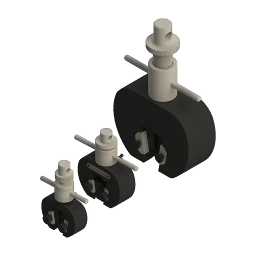
- Wedge grips for tensile test specimens
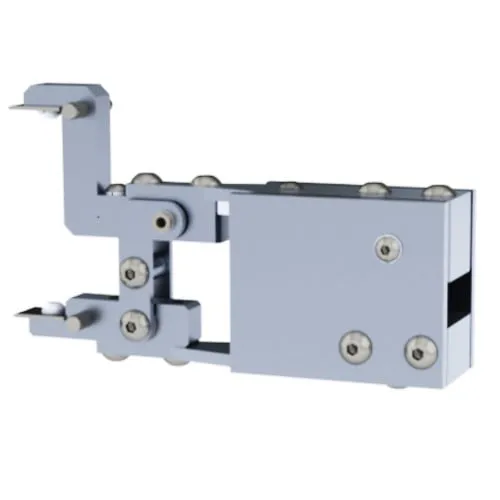
- Extensometer for Rp0.2, elongation and modulus of elasticity
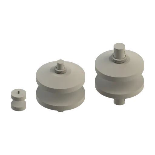
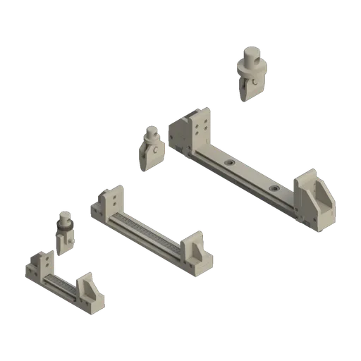
- Fixtures for compression, flexural and bend tests on the same frame
- BioLab software plots the stress-strain curve and builds the report
Fixtures for the complementary tests
The fixtures below are mounted on the same machine, depending on the test and the specimen:
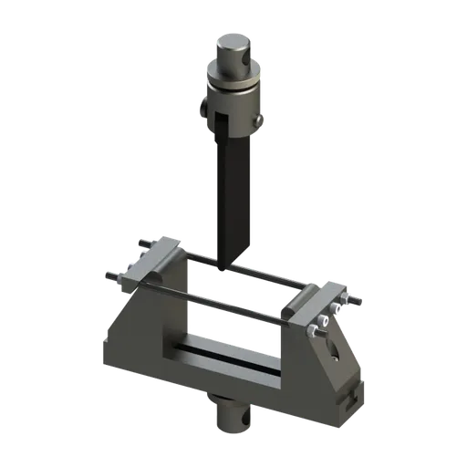
For the specimens in the examples in this article, with breaking forces between 16 and 33 kN, the right range is the 5 to 50 kN machine (MBIOII-50-M2). The load cell is class 1 per ABNT NBR ISO 7500-1:2023 (the Brazilian adoption of ISO 7500-1), and the BioLab software records the curve from which yield strength, elongation and modulus are obtained. The other capacities are on the universal testing machine page, and you can request a quote for the materials your laboratory tests. Charpy impact testing is done on a pendulum impact tester, which is not part of the Biopdi line.
Rockwell hardness test standards
The Rockwell hardness test is standardized by ISO 6508, in three parts (part 1 is the test method, part 2 the verification of the testing machine and indenters, and part 3 the calibration of reference blocks), and by ASTM E18. The table lists the standards cited, with the current edition checked on October 1, 2026 on the ISO and ASTM websites; the ABNT edition was checked in the catalog on September 30, 2026:
| Standard | Scope | Edition |
|---|---|---|
| ISO 6508-1 | Rockwell, test method (scales A to K, N and T) | 2023 |
| ABNT NBR ISO 6508-1 | Rockwell, test method (Brazilian adoption) | 2025 |
| ISO 6508-2 | verification and calibration of testing machines and indenters | 2023 |
| ISO 6508-3 | calibration of reference blocks | 2023 |
| ASTM E18 | Rockwell and superficial Rockwell hardness of metallic materials | E18-25 |
| ASTM E110 | Rockwell and Brinell hardness with portable hardness testers | E110-14(2023) |
| ISO 6506-1 | Brinell, test method (for comparison) | 2014 |
| ASTM E10 | Brinell hardness of metallic materials | E10-23 |
| ISO 6507-1 | Vickers, test method (for comparison) | 2023 |
| ASTM E92 | Vickers and Knoop hardness of metallic materials | E92-26 |
| ISO 18265 | conversion of hardness values | 2013 |
| ASTM E140 | hardness conversion tables | E140-12B(2019)e1 |
| ABNT NBR ISO 6892-1 | tensile testing of metals at room temperature | 2024 |
| ASTM E8/E8M | tensile testing of metals | E8/E8M-25 |
| ASTM A48/A48M | gray iron castings | A48/A48M-22 |
| ASTM A536 | ductile iron castings | A536-26a |
| SAE J1397 | estimated mechanical properties of steel bars (informative) | 1992, stabilized in 2024 |
The former ABNT NBR NM-ISO 6508-1 was replaced by NBR ISO 6508-1 in 2019, and the current Brazilian edition is the one from November 2025.
Other tests and technical references
Tests performed on the Biopdi universal testing machine



















Related technical references
Hardness test: types, procedure and standards (Brinell, Rockwell, Vickers and Shore)
A hardness test presses a standardized indenter into the part under controlled force and dwell time, then measures the indentation or its depth. See the types, the step-by-step procedure for each method, minimum thickness and spacing, hardness tester verification and standards.
Vickers hardness test and microhardness: HV formula, force ranges, case depth profile and conversion to HRC
Vickers and microhardness testing: HV = 0.1891·F/d², ISO 6507-1:2023 force ranges, case depth profile at 550 HV, HRC conversion and what hardness can't tell you.
Brinell hardness test: HBW formula, ball, load and the ISO 6506-1 and ASTM E10 standards
The Brinell hardness test presses a 1 to 10 mm carbide ball into the metal and calculates HBW from the indentation area. Formula, scales and ISO 6506-1.
Frequently asked questions
How does the Rockwell hardness test work?
A preliminary test force F0 (98.07 N on the regular scales) is applied, which sets the zero of the measurement; then the additional force F1 is applied, up to the total force of the scale, and held for about 5 s. F1 is removed and, still under F0, the instrument measures the permanent depth h. The hardness is HR = N − h/S: on the C scale, HRC = 100 − h/0.002.
What is Rockwell hardness?
Rockwell hardness is a dimensionless number that expresses a metal's resistance to indentation based on the permanent depth of the indentation, on a scale defined by indenter and force, such as HRC or HRBW. Each unit equals 0.002 mm of depth on the regular scales and 0.001 mm on the superficial scales, and a higher number means a harder material.
How is the Rockwell hardness test performed?
The hardness tester is verified that day with a reference block, the surface is cleaned, and the part is placed on a rigid support, perpendicular to the indenter. The preliminary force is applied for about 3 s, the additional force in 1 to 8 s, the total force is held for about 5 s, and the hardness is read about 4 s after returning to the preliminary force (ISO 6508-1:2023). Finally, thickness, spacing between indentations and curvature are checked.
What is the standard for the Rockwell hardness test?
ISO 6508-1:2023, adopted in Brazil as ABNT NBR ISO 6508-1:2025, and ASTM E18-25. Verification of the hardness tester follows ISO 6508-2:2023 and calibration of reference blocks follows ISO 6508-3:2023.
What is the Rockwell hardness standard scale?
The standard is the set of scales in ISO 6508-1:2023 and ASTM E18-25: the regular scales, with a preliminary force of 10 kgf and total forces of 60, 100 or 150 kgf, and the superficial scales, with a preliminary force of 3 kgf and forces of 15, 30 or 45 kgf. The most used are HRC, for hardened steel, and HRBW, for mild steel and nonferrous alloys. The reference block used to check the hardness tester is calibrated per ISO 6508-3:2023.
What does HRC mean?
It is Rockwell hardness on the C scale: 120° diamond cone, preliminary force of 98.07 N, total force of 1,471 N (330.7 lbf), range of 20 to 70 HRC. It is the scale for hardened steel. A reading of 59 HRC means a permanent depth of (100 − 59) × 0.002 = 0.082 mm.
What does HRB or HRBW mean?
It is the B scale: 1.5875 mm tungsten carbide ball, total force of 980.7 N (220.5 lbf), N = 130 and a range of 10 to 100 HRBW, used for mild steel, brass and aluminum alloys. The W indicates that the ball is tungsten carbide, the only type now allowed in the general method.
What is the difference between Rockwell and Brinell hardness tests?
Rockwell measures the depth of the indentation, with a direct reading and a small mark, and works well for hardened steel and production control. Brinell uses a ball of up to 10 mm, measures the indentation diameter under a microscope and, with its large mark, better represents heterogeneous materials such as cast iron. The two methods are compared in the article on hardness testing.
What is the difference between the A, B and C scales?
The A scale uses a diamond and 588.4 N (132.3 lbf), for cemented carbide and shallow case layers; the B scale uses a 1.5875 mm ball and 980.7 N (220.5 lbf), with N = 130, for soft materials; the C scale uses a diamond and 1,471 N (330.7 lbf), for hardened steel. Readings from different scales cannot be compared directly.
When should superficial Rockwell be used?
On thin sheet, small parts and shallow hardened case layers, where the regular scale would violate the minimum thickness. The N scales (diamond) and T scales (1.5875 mm ball) use a preliminary force of 29.42 N, total forces of 15, 30 or 45 kgf and S = 0.001 mm.
What is the minimum part thickness for the Rockwell test?
At least 10 times the permanent depth with a diamond and 15 times with a ball (ISO 6508-1:2023). For 60 HRC, h = 0.080 mm and the part must be 0.80 mm thick; for 80 HRBW, h = 0.100 mm and the part must be 1.50 mm thick. A visible mark on the back invalidates the test.
What is 300 HB in HRC?
About 32 HRC, from the ASTM E140 conversion tables for non-austenitic steels. The conversion is approximate, applies only to the material family of the table, and the converted value must be reported as such.
What is the difference between HRC and HB hardness?
HRC is Rockwell hardness on the C scale, obtained from the indentation depth of a diamond cone under 150 kgf; HB is Brinell hardness, obtained from the indentation diameter of a tungsten carbide ball and expressed as force per area. There is no exact formula between the two: in non-austenitic steels, 32 HRC corresponds to about 301 HB and 50 HRC to about 481 HB per ASTM E140, as an estimate.
Can tensile strength be obtained from Rockwell hardness?
Only as an estimate: in steels, Rm ≈ 3.45 × HB in MPa, or from the ISO 18265 and ASTM E140 tables, which consider this conversion the least reliable. In cast iron the estimate can be off by a factor of almost 3. For certification, the tensile test is performed on the universal testing machine.
Is the Rockwell test destructive?
In general it does not scrap the part: the indentation is less than 1 mm in diameter and the part usually stays in service, which is why Rockwell is considered nearly nondestructive. On a functional surface, such as a bearing raceway or a sealing face, the mark may not be acceptable, and the test is done on a non-working area or on a specimen from the same lot.
How are cylindrical parts tested with Rockwell?
The part is supported on a V-block or on twin cylinders of at least 60 HRC, the indenter is aligned with the top of the cylinder, and the curvature correction from Annexes C and D of ISO 6508-1:2023 is added to the reading and stated in the report. Corrections above 3 points on the A, C and D scales, or 5 on the B, F and G scales, are not accepted, and a different scale is used instead.
Does hardness replace the tensile test?
No. Hardness measures resistance to indentation at the surface and does not measure yield strength, elongation, necking, modulus or toughness. Two cast irons at 170 HB can have a minimum strength of 207 MPa and elongation below 1% (gray) or 414 MPa and 18% (ductile), and only the tensile test tells them apart.