
Plastic deformation is a permanent change in the shape of a material: the part of the deformation that remains in the part after the load is removed. In metals it begins at the yield strength, which in practice is Rp0.2, the stress that leaves 0.2% permanent strain. It happens mainly through the movement of dislocations (line defects in the crystal lattice) along planes of atoms, which is called slip, and to a lesser extent through twinning. Under load, the measured strain is the sum of an elastic part and a plastic part, ε = εe + εp. On unloading, only the elastic part is recovered, and what remains is εp = ε − σ/E.
Plastic deformation is the property that allows metals to be rolled, forged, drawn and stamped. It is also the reserve that lets a steel structure deform and give warning before it fractures. This article follows the order of a lecture. It defines plastic deformation and shows where it appears on the tensile test curve, then explains the mechanism and brings the formulas together. It then covers metal forming and ends with how to measure plastic deformation, worked examples and standards.
What is plastic deformation
While the stress is low, the deformation is elastic: the atoms move slightly away from their equilibrium positions and return when the force is removed. Above a certain stress level, part of the deformation becomes plastic. The atoms change neighbors and the part does not return to its original dimensions. Callister defines it as permanent, nonlinear deformation that persists after the load is removed.
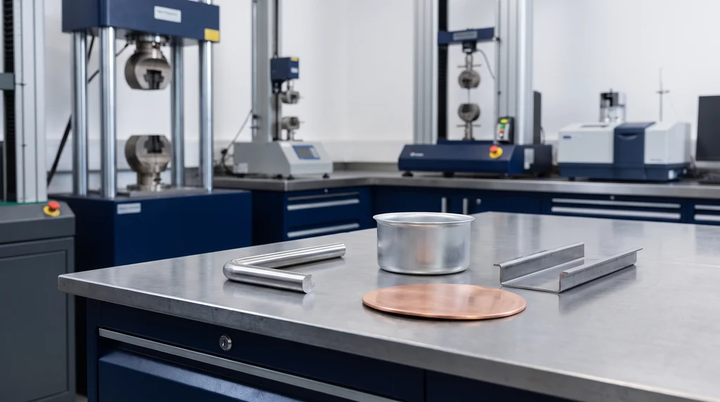
The photo shows cold-formed parts: a bar bent to 90°, a stamped aluminum cup, a flattened copper disc and a U-channel. In all of them the new shape is permanent, and that is what defines plastic deformation.
"Plastic" describes how the material behaves. It has nothing to do with polymers: a steel paper clip that is bent and stays bent has undergone plastic deformation. The ability to deform plastically without fracturing is called plasticity, and the tensile test measures it as ductility.
Plastic deformation and elastic deformation
Elastic deformation is reversible. In metals it is proportional to stress, following Hooke's law, σ = E·ε. Plastic deformation is permanent and nonlinear. The two are not separate phases that follow one another. After yielding, a loaded part still has an elastic component, σ/E, added to the plastic strain it has accumulated. The full comparison between the two is in the article on elastic deformation. This article focuses on what happens from yielding onward.
The loading and unloading cycle
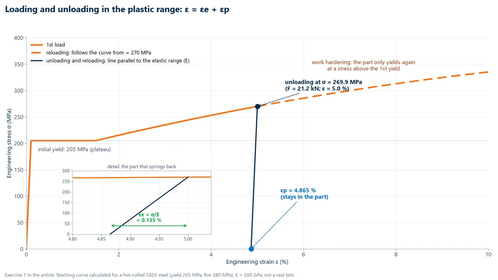
The clearest way to separate the two components is to load a test specimen beyond yield and then unload it. Unloading does not retrace the loading path. It follows a straight line parallel to the elastic portion, with the same slope E, and crosses the strain axis at εp. The difference between this value and the total strain is the elastic recovery, σ/E. In steel, E is high, so this recovery is on the order of a few tenths of a percent. The same component causes springback in a bent sheet.
The graph below shows the cycle using the numbers from Example 1, for a hot-rolled 1020 steel. When the part is loaded again, it rises along the unloading line and does not yield again until about 270 MPa. That is above the 205 MPa of the first yield. This is work hardening, visible on the curve itself.
Where plastic deformation begins on the stress-strain curve
On the stress-strain curve of a ductile metal, plastic deformation begins at yield and continues until fracture, in three stages. The first stage is the onset. The straight portion ends at the proportional limit, and just above it permanent strain becomes measurable at the yield point. Low-carbon steels show a yield plateau, with upper and lower yield strengths ReH and ReL. Aluminum, copper, stainless steel and work-hardened steels enter the plastic range gradually, and their yield strength is determined by the offset method, as Rp0.2.
The second stage is uniform plastic deformation. From yield up to the ultimate tensile strength, Rm, the whole gauge length deforms evenly and the stress rises because of work hardening. ISO 6892-1:2024 (ABNT NBR ISO 6892-1 in Brazil) calls the plastic extension at maximum force Ag, the uniform elongation. The third stage is localized deformation. From Rm onward, deformation concentrates in a neck (necking) until fracture. A common mistake is to think that plastic deformation begins at Rm. It begins at yield, and Rm marks the onset of necking.
Mechanism of plastic deformation: dislocations, slip and twinning
A metal is made of grains, and each grain is a crystal with its atoms arranged in planes. Plastic deformation happens when planes of atoms slide over one another. The question is how this sliding can happen at such low stresses.
Dislocations: why real metals yield at low stress
If all the atoms in a plane slid at the same time, the required stress would be a thousand times or more the value measured in the test. Taylor, Orowan and Polanyi each proposed the explanation independently in 1934: a real crystal contains dislocations, which are line defects in the lattice. Moving a dislocation requires breaking and re-forming the bonds along one line of atoms at a time, not across an entire plane. It is like moving a rug by pushing a wrinkle along it. Hirsch, Horne and Whelan first observed dislocations directly in 1956, in aluminum, using transmission electron microscopy.
In an edge dislocation, an extra half-plane of atoms is inserted into the crystal. The Burgers vector, which gives the magnitude and direction of the displacement, is perpendicular to the dislocation line. In a screw dislocation, the Burgers vector is parallel to the line. In real metals most dislocations are mixed. Each dislocation that crosses a grain leaves a step one atomic spacing high on the surface, and millions of these steps add up to the deformation we see with the naked eye.
Slip and slip systems
The movement of dislocations is called slip. It occurs preferentially on the planes with the highest atomic density, and within those planes along the most closely packed directions. The combination of plane and direction is a slip system. Slip begins when the shear stress on the system reaches a critical value. By Schmid's law, τR = σ·cos φ·cos λ, where φ is the angle between the force and the normal to the plane and λ is the angle between the force and the slip direction. In a polycrystal, the best-oriented grains yield first. For a grain to change shape along with its neighbors, the von Mises criterion requires at least five independent slip systems. The table summarizes the three most common crystal structures in metals, based on Callister:
| Structure | Plane and direction | No. of systems | Examples and behavior |
|---|---|---|---|
| Face-centered cubic (FCC) | {111} ⟨110⟩ | 12 | Al, Cu, Ni, austenite and austenitic stainless steel: very ductile |
| Body-centered cubic (BCC) | {110}, {112} and {123} ⟨111⟩ | 12 on {110}; 48 in total | ferrite, Mo, W, Cr: ductile, with a ductile-to-brittle transition at low temperature |
| Hexagonal close-packed (HCP) | (0001) basal ⟨11-20⟩ | 3 on the basal plane | Zn, Mg, α-Ti: less ductile at room temperature |
FCC combines close-packed planes with 12 slip systems and is the easiest structure to deform. This is why aluminum and copper can be drawn into fine wire and deep-drawn into stamped parts. BCC has more systems in total, but no plane as closely packed as in FCC, so it needs higher stresses. That does not make it brittle: the ferrite in steel is ductile at room temperature. What sets BCC apart is its ductile-to-brittle transition at low temperature. HCP has only three basal slip systems, fewer than the five von Mises requires, so it depends on harder slip planes and on twinning.
Twinning
In twinning, a region of the crystal undergoes homogeneous shear and becomes a mirror image of the lattice on the other side of a plane, called the twin plane. The deformation twinning produces is limited. Its importance is that it rotates parts of the grain into orientations where slip becomes easier. Twinning matters in HCP metals and, in BCC metals, at low temperatures and high strain rates. It is also called mechanical twinning or deformation twinning.
Ceramics, glasses and amorphous polymers
In ceramics, dislocations barely move at room temperature. In covalent ceramics such as silicon and diamond, the bonds are directional. In ionic ceramics such as NaCl, moving a dislocation brings ions of the same charge close together. A crack propagates before any significant plastic deformation occurs, so fracture is brittle. In amorphous materials such as glass and amorphous polymers, there are no crystal planes, and permanent deformation happens through viscous flow.
Creep is slow deformation under constant load at high temperature. It involves diffusion and grain boundary sliding, and it depends on time. Creep is a separate phenomenon, covered in the article on creep testing, not a third mechanism alongside slip and twinning.
Plastic deformation formulas
The formulas start from engineering strain, ε = (L − L0) / L0, which is the change in length divided by the original length. Under load, it is the sum of the two components, ε = εe + εp. Since the elastic part obeys Hooke's law, the residual plastic strain, which is what remains after unloading, is εp = ε − σ/E, with σ and E in the same unit. This is the calculation behind the loading and unloading cycle. It is also the basis of the offset yield strength: Rp0.2 is the stress at which εp = 0.002.
After fracture, two measurements record the total plastic deformation. Elongation after fracture is A = (Lu − L0) / L0 × 100, where Lu is measured by fitting the two broken halves together. Because the elastic part is recovered at the moment of fracture, A is essentially plastic. Reduction of area is Z = (S0 − Su) / S0 × 100, where Su is the smallest cross-section of the neck.
When plastic deformation is large, as in metal forming, true strain is used: εv = ln(L / L0) = ln(1 + ε). It is the sum of small length increments, each divided by the length at that instant. During plastic deformation of metals, volume stays practically constant, S0·L0 = S·L. True strain can therefore also be obtained from the areas, εv = ln(S0 / S), and true stress is σv = σ·(1 + ε). The conversions based on ε are valid up to Rm, while deformation is still uniform. Constant volume does not apply to the elastic component, nor to foams, porous materials or powders under compaction.
In industry, the amount of cold deformation a metal has received is expressed as percent cold work, %CW = (S0 − Sd) / S0 × 100, where Sd is the area after deformation. For rolled sheet, the same idea is written in terms of thickness, r = (h0 − h1) / h0. The table brings the formulas together:
| Quantity | Formula | Note |
|---|---|---|
| Total strain under load | ε = εe + εp | elastic plus plastic component |
| Residual plastic strain | εp = ε − σ/E | unloading parallel to the elastic portion |
| Offset yield strength | Rp0.2: stress at εp = 0.002 | ABNT NBR ISO 6892-1:2024 |
| Elongation after fracture | A = (Lu − L0) / L0 × 100 | report L0 |
| Reduction of area | Z = (S0 − Su) / S0 × 100 | Su at the neck |
| True strain | εv = ln(1 + ε) = ln(S0 / S) | up to Rm; additive between passes |
| True stress | σv = σ·(1 + ε) | up to Rm |
| Cold work | %CW = (S0 − Sd) / S0 × 100 | also in terms of thickness, in rolling |
The difference between engineering strain and true strain is negligible at small strains and grows quickly, as the calculated values below show. In compression, true strain is larger in magnitude than engineering strain, not smaller as in tension:
| Engineering ε | εv = ln(1 + ε) | Difference |
|---|---|---|
| 0.002 (0.2%) | 0.0020 | negligible |
| 0.05 | 0.0488 | 2.4% |
| 0.10 | 0.0953 | 4.7% |
| 0.20 | 0.1823 | 8.8% |
| 0.50 | 0.4055 | 18.9% |
| −0.20 (compression) | −0.2231 | 11.6% |
Consequence: work hardening, recovery and recrystallization
As plastic deformation proceeds, dislocations multiply and become tangled with one another. According to Callister, dislocation density rises from about 103 mm−2 in a carefully grown crystal to 109 to 1010 mm−2 in a heavily deformed metal. Each dislocation starts to obstruct the movement of the others, so more stress is needed to keep deforming the metal. This is work hardening. Yield strength and tensile strength increase and elongation decreases. The modulus of elasticity does not change, because it depends on the bonds between atoms, not on dislocations. 1020 steel shows the effect clearly. Hot-rolled, it yields at 205 MPa and elongates 25%. Cold-drawn, it yields at about 350 MPa and elongates about 15%.
Heat removes work hardening. During annealing, the metal first goes through recovery: dislocations rearrange and part of the internal stresses is relieved. Then comes recrystallization: new, strain-free grains form and dislocation density drops to 105 to 106 mm−2. Strength decreases again and ductility returns. How much a metal work hardens as it deforms is measured by the exponent n of the Hollomon equation, σv = K·εvn. For sheet, n is measured according to ASTM E646 or ISO 10275, and it is used with the cupping test to predict formability.
Metal forming
Plastic deformation is the phenomenon; metal forming (also called mechanical forming) is the set of industrial processes that use it to shape a solid metal without removing material. Rolling, forging, extrusion, wire drawing and stamping are the main ones. The standard Brazilian reference on the subject is the book Conformação Plástica dos Metais (Plastic forming of metals), by Bresciani Filho, Button and coauthors, published by Editora da Unicamp (Unicamp University Press).
Processes by type of loading
Processes are classified by the type of loading that produces the deformation, as Dieter does in Mechanical Metallurgy. The German standard DIN 8582:2003 uses an equivalent classification based on the stress state. In direct compression, the tool compresses the metal. In indirect compression, the metal is pulled or pushed, and the wall of the tool generates the compression that deforms it. The table summarizes the most common processes:
| Loading | Process | What happens | Typical product |
|---|---|---|---|
| Direct compression | Rolling | the metal passes between rotating rolls and its thickness decreases | plates and sheets, coils, sections, rails, rebar |
| Direct compression | Forging | a hammer or press compresses the metal between dies | crankshafts, connecting rods, tools, flanges |
| Indirect compression | Extrusion | a ram pushes the billet through a die with the profile shape | aluminum profiles, tubes |
| Indirect compression | Wire drawing | wire or bar is pulled through a conical die | steel wire, copper wire, CA-60 reinforcing wire (a Brazilian rebar grade) |
| Indirect compression | Deep drawing | the punch pushes the sheet into the die | cans, sinks, oil pans |
| Tension | Stretch forming | the sheet is stretched over a form while clamped at the edges | large-radius panels |
| Bending | Bending and roll bending | bending moment | angles, rolled tubes, stirrups |
| Shear | Shearing and punching | localized shear until separation | blanks, washers |
The process in which the material passes between rolls is therefore rolling. In deep drawing, the same part undergoes different loading in each region: the flange is compressed in the circumferential direction and the wall is in tension. This is why the formability of a sheet is evaluated with a dedicated test and not only by its elongation in a tensile test.
Cold, warm and hot working
The same deformation has different effects depending on the temperature at which it is applied, and the temperature that matters is the one relative to the melting point, measured in kelvin: the homologous temperature, T/Tm. In cold working, below about 0.3 Tm, there is no recovery or recrystallization during the process: work hardening accumulates, surface finish and dimensional accuracy are good, and the total deformation is limited, requiring intermediate annealing. In warm working, from 0.3 to 0.5 Tm, recovery occurs but no new grains form. In hot working, above about 0.5 Tm, recrystallization takes place during deformation, the required force is lower and very large deformations are possible. These ranges are the ones given in the teaching material of CIMM (a Brazilian metalworking information portal).
The boundary that actually separates cold from hot working is the recrystallization temperature, defined as the temperature at which recrystallization is complete in one hour. As a rule of thumb, it lies between 0.3 and 0.6 Tm, and it decreases with the purity of the metal and with the amount of prior cold work; below a minimum deformation, the critical strain, there is no recrystallization. For iron it is around 450 °C, and for tungsten close to 1,200 °C. Lead and tin recrystallize below 20 °C: bending a lead pipe at room temperature is, technically, hot working, and the pipe does not work harden.
The chart below compares room temperature with the melting temperature of nine pure metals. For iron, copper and tungsten, 20 °C is well inside the cold working range; aluminum sits on the boundary; lead and tin are already close to or above half of Tm.
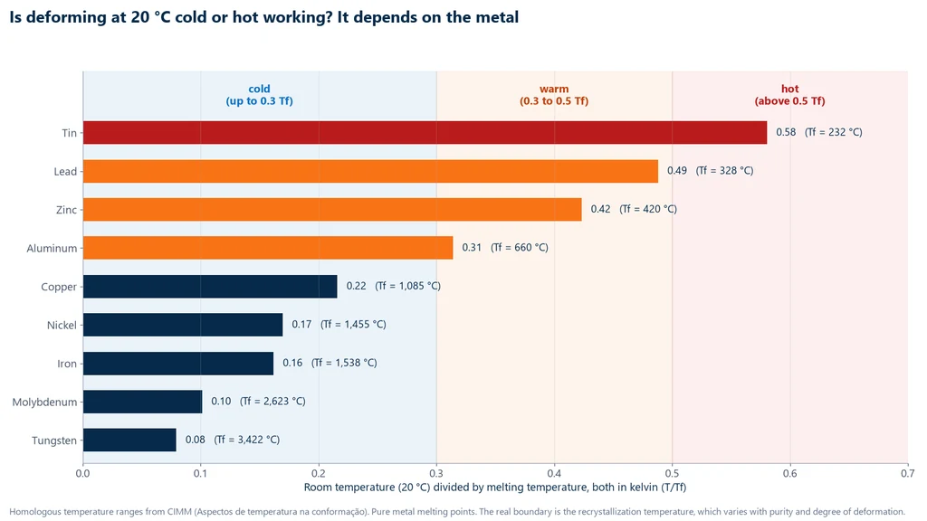
The table summarizes the three ranges. The article on heat treatment of metals covers the thermal cycles that accompany forming, and the article on malleability covers the ability to be formed into sheets by compression.
| Regime | Homologous temperature | What happens |
|---|---|---|
| Cold | up to about 0.3 Tm | work hardens; good accuracy; limited deformation |
| Warm | 0.3 to 0.5 Tm | recovery, no new grains |
| Hot | above about 0.5 Tm | recrystallizes while deforming; lower force; large deformations |
Examples of plastic deformation
Plastic deformation is present in everyday objects and in almost every manufactured metal part. Some examples, with the process or situation that produces them:
- A bent paper clip that does not spring back: low-carbon steel wire deformed beyond yield.
- Aluminum can: made by deep drawing and wall ironing, and crushed, again plastically, when discarded.
- Car body: stamped panels and, in a collision, the crumple zone, which absorbs energy by deforming plastically.
- Rebar bent on site into stirrups and hooks; the bend test in ABNT NBR 7480 (the Brazilian standard for steel reinforcing bars) verifies this capacity.
- Copper wire (wire drawing), aluminum window profile (extrusion), rail and plate (rolling) and open-end wrench (forging).
- Coin: struck by closed-die forging (coining).
Polymers also deform plastically, through a different mechanism. In a semicrystalline thermoplastic, such as polyethylene or nylon, the stress passes through a yield maximum, drops, and a neck forms and propagates along the test specimen while the chains and lamellae align in the loading direction: this is cold drawing, which can take elongation to hundreds of percent. In amorphous polymers below the glass transition, permanent deformation occurs by shear banding and viscous flow. The test follows ASTM D638 or ISO 527-1. The article on types of materials compares the material families.
How to measure plastic deformation in the tensile test
Plastic deformation is measured in the tensile test, according to ISO 6892-1 (ABNT NBR ISO 6892-1:2024 in Brazil) or ASTM E8/E8M-25. The universal testing machine applies the force at a controlled rate, the load cell measures the force F and the extensometer, attached to the test specimen, measures the elongation over the gauge length L0. The software converts the readings into stress and strain and calculates the results required by the standard: yield (ReH, ReL or Rp0.2), Rm, uniform elongation Ag, elongation after fracture A and reduction of area Z.
The extensometer is essential for Rp0.2. Crosshead displacement includes grip slack and the elastic deformation of the machine and load cell, and it overestimates the specimen strain precisely in the region where the 0.2% offset line is drawn. After yield, some laboratories remove the extensometer and continue with the crosshead, which must be stated in the report. A test programmed with loading and unloading cycles, like the one in exercise 1, directly shows the permanent deformation and the elastic recovery.
Some product specifications set a minimum plastic deformation. CA-50 rebar (a Brazilian rebar grade), for example, requires elongation after fracture A ≥ 8%, measured over 10 diameters, in addition to fyk ≥ 500 MPa and fst/fy ≥ 1.10 (ABNT NBR 7480:2024); this plastic reserve is what makes a reinforced concrete structure deform and crack visibly before it fails. For deep drawing sheet, the relevant figure is the strain hardening exponent n, measured according to ASTM E646 or ISO 10275. The article on ductility details A and Z, and the article on the tensile test covers the complete procedure.
Solved exercises
The five exercises follow the order of the article: the deformation that remains after unloading, true strain in forming and the working temperature.
Exercise 1: permanent deformation after unloading
A hot-rolled 1020 steel test specimen, with d0 = 10.0 mm and an extensometer with L0 = 50.0 mm, is loaded in tension in a universal testing machine. At F = 21.2 kN, the extensometer reads ΔL = 2.50 mm, and the load is removed. With E = 200 GPa, what is the final length between the extensometer knife edges?
- Area: S0 = π × 10.0² / 4 = 78.54 mm².
- Stress: σ = 21,200 / 78.54 = 269.9 MPa, above the yield strength of 205 MPa.
- Total strain: ε = 2.50 / 50.0 = 0.0500.
- Elastic recovery: εe = σ/E = 269.9 / 200,000 = 0.00135, or 0.0675 mm.
- Permanent strain: εp = 0.0500 − 0.00135 = 0.04865 (4.865%), or 2.43 mm.
The final length is 52.43 mm. Of the 2.50 mm of elongation under load, only 0.07 mm is recovered. If the part is loaded again, it will only yield again at around 270 MPa: the first cycle work hardened the material.
Exercise 2: reduction of area and true strain in wire drawing
A 5.0 mm copper wire is drawn to 4.0 mm in one pass. Calculate the cold work and the true strain.
- Area ratio: S0/S1 = (5.0 / 4.0)² = 1.5625.
- Cold work: %CW = (1 − 1/1.5625) × 100 = (1 − 0.64) × 100 = 36%.
- By volume constancy, L1/L0 = 1.5625: the wire becomes 56.25% longer.
- True strain: εt = ln 1.5625 = 0.446.
The engineering strain along the length would be 0.5625, quite different from the true strain of 0.446: in forming, the two measures diverge.
Exercise 3: true strain in tension and compression
A 50 mm bar is stretched to 60 mm; another identical bar is compressed to 40 mm. Compare the strains.
- Tension: ε = 10 / 50 = +0.200; εt = ln(60 / 50) = +0.182.
- Compression: ε = −10 / 50 = −0.200; εt = ln(40 / 50) = −0.223.
In engineering strain the two look symmetrical, ±20%. In true strain, the compression is larger in magnitude. This is why forming and simulation work with εt.
Exercise 4: rolling in two passes
A 10 mm plate is rolled to 7 mm and then to 5 mm. Add the strains of the two passes and compare with the direct total, in magnitude.
- Engineering: pass 1, 3/10 = 0.300; pass 2, 2/7 = 0.286; sum 0.586. The direct total is 5/10 = 0.500. They do not match.
- True: ln(10/7) = 0.357; ln(7/5) = 0.336; sum 0.693. The direct total is ln(10/5) = 0.693. They match.
Only true strain is additive between passes, and it is the one used to plan a rolling or wire drawing sequence.
Exercise 5: cold or hot working?
Taking a recrystallization temperature of 0.4 Tm, classify rolling at 20 °C of lead (Tm = 327.5 °C) and of iron (Tm = 1,538 °C).
- Lead: Tm = 600.7 K; 0.4 Tm = 240 K, or −33 °C. At 20 °C (293 K, 0.49 Tm), lead is above its recrystallization temperature: hot working.
- Iron: Tm = 1,811 K; 0.4 Tm = 724 K, or 451 °C, consistent with the roughly 450 °C mentioned above. At 20 °C (0.16 Tm) it is cold working, and iron work hardens.
"Cold" and "hot" are relative to the melting temperature of the metal, not to how warm it feels.
Common mistakes about plastic deformation
Besides the misconceptions already pointed out throughout the text (plastic deformation starting at Rm, creep as a mechanism, BCC as brittle, adding engineering strains), four mistakes appear frequently in course notes, websites and reports:
- Listing work hardening as a mechanism of plastic deformation. It is a consequence: the increase in strength caused by the multiplication of dislocations. The mechanisms are slip and twinning.
- Treating plastic deformation in service as normal behavior. Structural design works below yield; plastic deformation is the goal in manufacturing and the safety reserve in the structure, not the working regime.
- Reading the number in CA-60 as tensile strength. The 600 MPa is the characteristic yield strength, fyk, like the 500 MPa of CA-50.
- Calling refractory ceramics "aluminum and silicon". Refractories are oxides and silicates, such as alumina (Al2O3) and silica (SiO2); aluminum is a metal and silicon a metalloid.
Standards for measuring plastic deformation
The standards below define how to measure plastic deformation in tension, the strain hardening exponent of sheet and the minimum values required for products. The table lists those cited in the article, with the current edition:
| Standard | Scope | Edition |
|---|---|---|
| ABNT NBR ISO 6892-1 | tensile testing of metals at room temperature (Brazilian adoption of ISO 6892-1): Rp0.2, Ag, A and Z | 2024 |
| ISO 6892-1 | tensile testing of metals at room temperature | 2019 |
| ASTM E8/E8M | tension testing of metals | E8/E8M-25 |
| ASTM E646 | strain hardening exponent n of metallic sheet | E646-16(2024) |
| ISO 10275 | strain hardening exponent n of sheet and strip | 2020 |
| ASTM E111 | modulus of elasticity, used to separate εe from εp | E111-17(2025)e1 |
| ABNT NBR 7480 | Brazilian standard for steel bars and wires for reinforced concrete: elongation and bend test | 2024 |
| ASTM D638 | tensile testing of plastics | D638-22 |
| ISO 527-1 | tensile testing of plastics, general principles | 2019 |
| DIN 8582 | classification of forming processes | 2003 |
Machine for measuring plastic deformation
Measuring plastic deformation requires applying the force at a controlled rate, measuring the force with a load cell suited to the test, and measuring the elongation on the specimen itself with an extensometer, so that the elastic part can be separated from the plastic part. The Biopdi M2 universal testing machine is electromechanical and does all three. It comes in single-column models from 200 N to 10 kN and dual-column models from 5 kN to 1,000 kN, with extensometers and the BioLab software. The panel below shows the machine, the role of each part in the measurement and the grips used.
The universal testing machine in the tensile test
The M2 line has single-column models from 200 N to 10 kN and dual-column models from 5 kN to 1,000 kN. Each part of the machine has a role in measuring plastic deformation:

- Moving crosshead pulls the specimen and runs loading and unloading cycles
- Load cell measures the force F, class 1
- Grips: wedge, pneumatic, for threaded specimens or for wires
- Extensometer measures ΔL over the gauge length L0 and separates εe from εp
- BioLab software calculates Rp0.2, Rm, Ag, A and Z
- Control panel and emergency stop position the crosshead and stop the test
Fixtures for the tensile test
The fixtures below are mounted on the same machine, depending on the specimen and the standard:
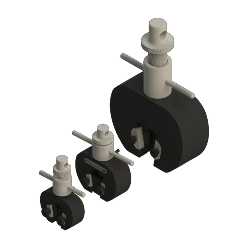 Wedge grip5, 20 and 200 kN
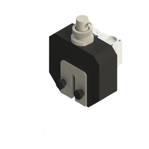 Pneumatic wedge grip50 and 200 kN
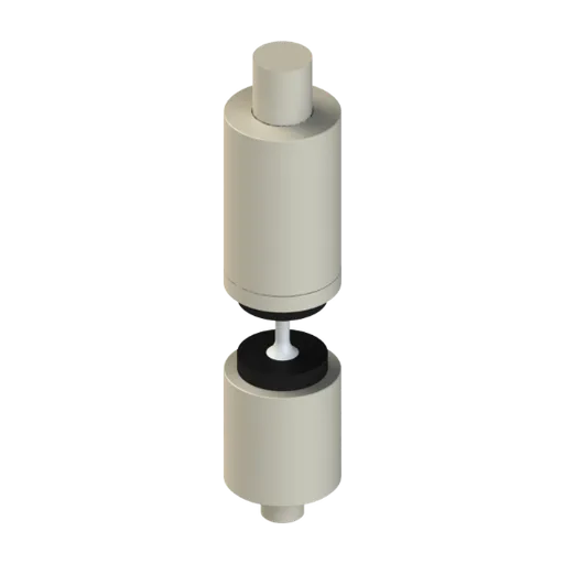 Grip for threaded specimensbolts and threaded specimens
For sheet metal and metal specimens, the typical model is the 5 to 50 kN universal testing machine (MBIOII-50-M2); for reinforcing bars such as CA-50 (the Brazilian rebar grade defined in ABNT NBR 7480), the 100 to 200 kN machine (MBIOII-200-M2); for polymers and cold drawing, the single-column machine. The BioLab software plots the curve and calculates the results required by the standard, and the metallurgical microscope completes the analysis, showing the elongated grains of a cold-worked metal and the equiaxed grains after recrystallization. The other capacities are on the universal testing machine page.
Other tests and technical references
Work hardening: what it is, mechanism, Hollomon equation (n-value), annealing and how to measure it
Work hardening (strain hardening) is the strengthening of a metal by cold plastic deformation: yield strength, tensile strength and hardness go up, ductility goes down, and the modulus of elasticity does not change. Learn the dislocation mechanism, the percent cold work (%CW), the Hollomon equation and the strain hardening exponent n, its measurement per ISO 10275 and ASTM E646, annealing, and solved exercises.
Elastic limit and yield strength: what they are, the difference, formula, Rp0.2 and steel table
The elastic limit is the highest stress without permanent strain; yield strength is where plastic strain becomes measurable (ReH and ReL, or Rp0.2). See the formula, symbols, 0.2% offset, steel table, CA-50 and exercises.
Hardness of materials: what it is, scales and HRC, HB and HV conversion chart
Hardness is a material's resistance to localized plastic deformation. Types, scales, HRC × HB × HV chart, what 60 HRC means and steel hardness.
Ultimate tensile strength (Rm): what it is, formula, graph, steel table and how to measure it
Ultimate tensile strength (Rm) is the engineering stress at the maximum force of the tensile test: Rm = Fm/S0. See the symbols, where it sits on the graph, how it differs from yield strength and fracture stress, the steel table with material condition, CA-50 (Brazilian rebar grade), breaking load, the estimate from hardness, and exercises.
Frequently asked questions
What is plastic deformation?
It is the permanent change of shape of a material, the part of the deformation that remains after the load is removed. In metals it begins at the yield strength, which in practice is Rp0.2, the stress that leaves 0.2% permanent strain (ISO 6892-1, adopted in Brazil as ABNT NBR ISO 6892-1:2024).
What is plastic deformation in metals?
It is the permanent deformation produced by the movement of dislocations along close-packed crystal planes (slip) and, to a lesser extent, by twinning. It is what allows metals to be rolled, forged and drawn without fracturing.
What is the difference between elastic and plastic deformation?
Elastic deformation is reversible and proportional to stress, according to Hooke's law. Plastic deformation is permanent and nonlinear. Under load the two coexist, ε = εe + εp; on unloading, only the elastic part σ/E is recovered.
What is the formula for plastic deformation?
The residual plastic strain is εp = ε − σ/E. For large deformations, true strain is used, εv = ln(1 + ε) = ln(S0/S). In the test, the elongation after fracture A = (Lu − L0)/L0 × 100 measures the total plastic deformation.
What is plastic forming?
It is the set of industrial processes that shape solid metal by plastic deformation, without removing material: rolling, forging, extrusion, drawing and stamping.
What is the process in which the material passes between rolls called?
Rolling. The metal passes between rotating rolls and comes out thinner, forming sheets, coils, sections and reinforcing bars. It is a direct compression process.
Why are FCC metals more ductile than HCP metals?
FCC metals, such as aluminum, copper and nickel, have 12 slip systems on close-packed {111} planes. HCP metals, such as zinc and magnesium, have only 3 on the basal plane at room temperature. More available systems mean more paths for dislocations and greater ductility.
What is twinning?
It is the mechanism in which a region of the crystal is sheared and becomes the mirror image of the neighboring lattice. It is important in HCP metals and, in BCC metals, at low temperature and high strain rate, and it helps reorient grains for slip.
What is the difference between cold working and hot working?
Cold working takes place below about 0.3 of the melting temperature, in kelvin, and the metal work hardens. Hot working takes place above the recrystallization temperature, about 0.5 Tm, and the metal recrystallizes as it deforms. For lead, room temperature is already hot working.
Does plastic deformation increase the strength of a metal?
Yes, through work hardening. The dislocation density rises from about 10³ to 10⁹ to 10¹⁰ mm⁻², which raises the yield strength and tensile strength and reduces elongation. The modulus of elasticity does not change, and annealing reverses the effect.
How is plastic deformation measured?
With a tensile test on a universal testing machine with an extensometer, according to ISO 6892-1 (ABNT NBR ISO 6892-1:2024 in Brazil) or ASTM E8/E8M-25. The results are Rp0.2, Ag, A and Z. For sheet metal, the strain hardening exponent n is obtained according to ASTM E646 or ISO 10275.
Do polymers undergo plastic deformation?
Yes. Semicrystalline thermoplastics yield, form a neck and undergo cold drawing, which aligns the chains. The test follows ASTM D638 or ISO 527-1. This is different from forming plastics by injection or blow molding.