
The Vickers hardness test presses a square-based diamond pyramid, with 136° between opposite faces, into the material, measures the two diagonals of the indentation and calculates hardness as the force divided by the area of the faces: HV = 0.1891·F/d², with F in newtons and d, the mean of the diagonals, in millimeters. Under ISO 6507-1:2023, the same formula applies from the macro test (forces from 49.03 N, HV 5) down to microhardness (below 1.961 N, HV 0.2). In microhardness testing, the indentation measures tens of micrometers across and is used to measure layers, phases and coatings, such as the depth of a carburized case.
In short:
- Formula: HV = 0.1891·F/d² (F in N, d in mm). The 0.1891 comes from the pyramid geometry: 2·sin 68° / 9.80665.
- ISO 6507-1:2023 ranges: Vickers from HV 5; low-force from HV 0.2 to less than HV 5; microhardness from HV 0.001 to less than HV 0.2. Valid diagonal from 0.020 to 1.400 mm.
- Specimen rules: thickness of at least 1.5 d; in steel, 3 d between centers and 2.5 d to the edge.
- Case depth profile: the effective case hardening depth (CHD) is where the profile crosses 550 HV (ISO 18203:2026).
- Limit of the method: hardness measures a single variable, the resistance to localized indentation. Yield strength, elongation, modulus of elasticity and toughness come from tensile, compression, flexural, bend and impact tests.
The overview of hardness methods (Brinell, Rockwell, Vickers, Shore and Leeb), hardness tester verification and how to choose between them are covered in the article hardness test, and the concept of hardness with the full HRC, HV and HB table is in hardness of materials. This article goes deeper into the Vickers method: where the formula comes from, how to choose the force, how to prepare the sample for microhardness, how to read a case depth profile, how to convert and, above all, what the HV number does not tell you about the material.
How the Vickers test works
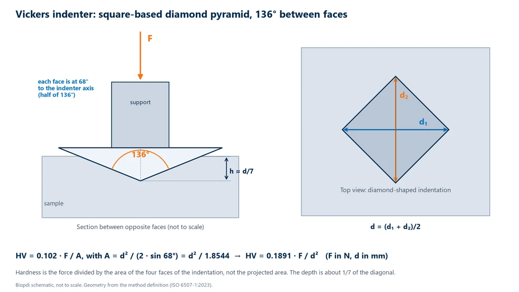
In the Vickers test, the indenter is a right square-based diamond pyramid with an angle of 136° between opposite faces. It is pressed into the surface with a known force F, held for a defined time and removed. It leaves a rhombus-shaped indentation whose two diagonals, d1 and d2, are measured under a microscope or with an imaging system. Hardness is the force divided by the sloping area of the indentation, that is, the sum of the areas of the four faces, assuming the indentation reproduces the geometry of the indenter.
The diagram below shows the two views. In the cross section, each face is at 68° to the indenter axis, half of 136°, and the depth h is small compared with the width. In the top view, the rhombus and its two diagonals, whose mean d = (d1 + d2)/2 is used.
Where the 0.1891 comes from
The area of the four faces of a square-based pyramid with diagonal d and an angle of 136° between faces is A = d² / (2·sin 68°). Since sin 68° = 0.92718, the denominator is 1.85437 and A = d²/1.8544. Vickers hardness is defined in kilogram-force per square millimeter, by tradition; with the force in newtons, the factor 0.102 comes in, which is 1/9.80665, the inverse of standard gravitational acceleration. So:
HV = 0.102 × F / A = 0.102 × 1.8544 × F / d² = 0.1891 × F / d²
The direct calculation gives 1.85437 / 9.80665 = 0.18909. With the force in kilogram-force, the same formula becomes HV = 1.8544·F/d², which is the version found in older texts. By convention, the result is written without a unit.
The same geometry gives the depth. In the pyramid, the depth is h = d / (2·√2·tan 68°) = d / 7.0006, that is, h ≈ d/7. An indentation with a 0.300 mm diagonal sinks only 0.043 mm. This relationship explains two rules that appear later: the minimum specimen thickness and the care with roughness in microhardness testing.
Notation and origin of the name
The result is written with the value, the symbol HV and the force in kilogram-force: 640 HV 30 is a hardness of 640 measured with 30 kgf (294.2 N), at the standard dwell time. If the force dwell time is different, it follows a slash: 640 HV 30/20 indicates 20 s. In microhardness, the force appears as a decimal: 580 HV 0.5 was measured with 4.903 N.
The name comes from the British company Vickers. The engineers R. L. Smith and G. E. Sandland, who worked for it in Erith, England, published the method in 1922 in the Proceedings of the Institution of Mechanical Engineers (vol. 102, pp. 623-641). The title of the paper already stated the purpose: to measure the hardness of metals accurately, with particular attention to very hard ones, on which the steel ball used in the Brinell test of the time deformed. Many texts give 1925 as the year of creation; the original publication is the 1922 one.
Why a single scale covers soft metal to hard metal
Vickers hardness is a single, continuous scale, with no sub-scales, that measures from lead to cemented carbide with the same indenter. Brinell changes ball and force depending on the material, and Rockwell has a scale letter for each combination of indenter and force. Vickers does not need this, for a geometric reason. Every pyramid indentation is similar to the others: as the force increases, the indentation grows but keeps the same angle and the same ratio between depth and diagonal. The strain imposed on the material therefore does not change with the size of the indentation, and the HV number of a homogeneous material is practically independent of the force. With a ball, by contrast, a shallow and a deep indentation have different shapes, which is why Brinell requires fixing the ratio between force and diameter.
The diamond, in turn, hardly deforms against any metal, so a single indenter is enough. This is what makes Vickers the reference method in research, in comparing very different materials and in profiles that cross regions of very different hardness in the same section, such as a hardened case over a soft core.
Force independence has a limit. At very low forces, many materials show higher hardness than in the macro test, an effect known as the indentation size effect (ISE). Part of it comes from the physics of small-scale deformation and part from the test itself: the diamond tip is never perfect, a diagonal of a few micrometers has a large relative optical uncertainty, and the layer work hardened by preparation weighs more. That is why a microhardness value can only be compared with another measured at the same force, and the force always appears in the notation.
Force ranges: Vickers, low-force and microhardness
ISO 6507-1:2023 divides the method into three ranges by test force: Vickers (the macro range, also called macrohardness), low-force Vickers and Vickers microhardness. The indenter, the formula and the diagonal measurement are the same; what changes is the size of the indentation, the required surface finish and what can be measured. The table shows the three:
| Range (ISO 6507-1:2023) | Force | Symbols | What it measures |
|---|---|---|---|
| Vickers | 49.03 N or more | HV 5 or more | average hardness of the part |
| Low-force Vickers | 1.961 N to less than 49.03 N | HV 0.2 to less than HV 5 | thin parts, layers, welded joints |
| Vickers microhardness | 0.009807 N to less than 1.961 N | HV 0.001 to less than HV 0.2 | phases, shallow layers, coatings |
In all ranges, ISO only accepts diagonals from 0.020 mm to 1.400 mm. Below 0.020 mm, the uncertainty of the optical measurement and the imperfections of the tip make the result invalid, and the way forward is instrumented indentation under ISO 14577-1:2026, which records force and depth throughout the whole cycle, without measuring the indentation under a microscope.
Within each range, the standard lists nominal forces, named by their value in kilogram-force. In the macro range they are HV 5, HV 10, HV 20, HV 30, HV 50 and HV 100 (49.03 N to 980.7 N), and the most used in practice is HV 30 (294.2 N). In the low-force range, HV 0.2, HV 0.3, HV 0.5, HV 1, HV 2 and HV 3. In microhardness, the most common go from HV 0.01 to HV 0.1, such as HV 0.025, HV 0.05 and HV 0.1. Using a nominal force from the list is what allows results from different laboratories to be compared.
ASTM divides things differently. ASTM E92-26 covers Vickers and Knoop hardness of metallic materials, and ASTM E384-22 covers microindentation hardness, Vickers and Knoop, with forces from 1 gf to 1,000 gf (9.807 mN to 9.807 N). What ASTM calls microindentation therefore goes up to HV 1 and covers ISO microhardness and part of the low-force range. When reading a report, the force stated explicitly in the notation resolves the ambiguity: "microhardness" without a force does not say whether it was HV 0.01 or HV 1.
The minimum diagonal limits the force on hard materials
The minimum diagonal rule has a practical consequence that is often forgotten: too low a force on a hard material produces an indentation smaller than 0.020 mm, outside the scope of the standard. From the formula, the highest hardness that still gives a 0.020 mm diagonal is HVmax = 0.1891 × F / 0.020² = 472.75 × F, with F in newtons. The table shows the result for the usual microhardness and low-force loads:
| Force | F (N) | Highest hardness with d ≥ 0.020 mm |
|---|---|---|
| HV 0.01 | 0.09807 | 46 HV |
| HV 0.05 | 0.4903 | 232 HV |
| HV 0.1 | 0.9807 | 464 HV |
| HV 0.2 | 1.961 | 927 HV |
| HV 0.5 | 4.903 | 2,318 HV |
| HV 1 | 9.807 | 4,636 HV |
A nitrided layer of 900 HV, for example, cannot be measured at HV 0.1: the diagonal would come out at 0.014 mm. At HV 0.5, it would be 0.032 mm. Choosing the force is therefore a balance: too high a force makes the indentation go through the layer or phase you want to measure; too low a force gives a small, uncertain diagonal.
Vickers test procedure
The Vickers test procedure has six steps, the same in all three force ranges: prepare the surface, support the part, choose the force, apply and hold the force, measure the diagonals and calculate. What changes between ranges is the care taken with the surface and the microscope magnification. Under ISO 6507-1:2023, the sequence is:
- Prepare the surface: smooth, flat, free of oxide and lubricant, with a finish that lets you see the corners of the rhombus. The lower the force, the better the finish (next section).
- Support the part on a rigid anvil, with the surface perpendicular to the indenter axis. Small or thin parts are mounted in resin.
- Choose the force according to the thickness of the part or layer and the expected hardness, checking the minimum thickness and the minimum diagonal.
- Apply the force without shock, reaching the full value in 2 to 8 s (7 s nominal), and hold it for 10 to 15 s (14 s nominal). A different time goes into the notation.
- Measure both diagonals and calculate the mean. If they differ by more than 5%, the difference goes into the report: it usually indicates a surface tilted relative to the indenter or an anisotropic material.
- Calculate HV with the formula or the tables in the standard, and record the full notation, with the force.
The test is performed between 10 °C and 35 °C, and ISO 6507-1 provides correction factors for spherical and cylindrical surfaces, because on a curved surface the indentation comes out distorted. The force cycle, daily verification on the reference block and calibration of the hardness tester (ISO 6507-2 and ISO 6507-3) are described in the article hardness test.
Advantages and disadvantages of the Vickers test
The Vickers test trades speed for versatility: one indenter and one scale serve all metals, but each reading requires a prepared surface and optical measurement of the diagonals. The advantages are:
- Single scale: the same diamond and the same formula apply from soft metal to cemented carbide, and the HV numbers of different materials can be compared directly.
- Force independence: in a homogeneous material, HV 10 and HV 30 give practically the same value, which does not happen between Rockwell scales.
- Small indentation: the test is almost non-destructive and, at low force, measures thin parts, layers, coatings and individual phases.
- Non-deforming indenter: the diamond does not flatten on hard material, as the steel ball of the old Brinell test did.
The disadvantages come from the optical measurement:
- Prepared surface: the corners of the rhombus must be seen sharply, which requires a flat surface and, for microhardness, a polished one.
- Slower than Rockwell: Rockwell reads depth on the instrument itself; Vickers requires focusing and measuring two diagonals under the microscope.
- Reading dependence: in manual measurement, the placement of the lines on the corners varies between operators, especially on small indentations; imaging systems reduce this variation.
- Small volume: the indentation represents a small region. In coarse, heterogeneous material such as cast iron, the Brinell test, with a large ball, gives a more representative average.
Minimum thickness, spacing and choice of force
The minimum thickness and the spacing between indentations exist because the indentation plastically deforms a region much larger than the mark itself. If the part is thin, that region reaches the back face, the anvil starts supporting the indentation and the reading comes out high; a visible mark on the back invalidates the test. Near the edge, there is not enough material to contain the deformation and the reading comes out low. Near another indentation, the diamond lands in the region the first one work hardened.
That is why ISO 6507-1:2023 sets three limits, all as multiples of the diagonal d:
- Minimum thickness: 1.5 d, for the whole part or for the layer to be measured.
- Distance between centers: 3 d in steel, copper and copper alloys; 6 d in light metals, lead, tin and their alloys. With indentations of different sizes, the diagonal of the largest applies.
- Distance from center to edge: 2.5 d in steel, copper and copper alloys; 3 d in light metals, lead, tin and their alloys.
Light metals need more space because, being softer, they leave indentations whose deformed zone extends further relative to the diagonal. Since the limits depend on the diagonal, and the diagonal depends on force and hardness, the force is chosen before the test using the inverted formula, d = √(0.1891·F/HV). The table shows the expected diagonals for two typical hardness values, one for annealed steel and one for quenched steel:
| Force | d at 200 HV (mm) | d at 600 HV (mm) | Minimum thickness at 200 HV (mm) |
|---|---|---|---|
| HV 30 (294.2 N) | 0.527 | 0.304 | 0.79 |
| HV 10 (98.07 N) | 0.304 | 0.176 | 0.46 |
| HV 1 (9.807 N) | 0.096 | 0.056 | 0.14 |
| HV 0.1 (0.9807 N) | 0.030 | 0.018 (below 0.020: invalid) | 0.046 |
Two conclusions come from the table. First: a 0.5 mm steel strip cannot be tested at HV 30, but it can at HV 10 (exercise 3). Second: the same force that works on an annealed steel can fall below the minimum diagonal on a quenched steel, as in the last row.
Sample preparation for microhardness testing
Sample preparation for microhardness testing is the sequence of cutting, mounting, grinding and polishing that leaves the surface flat, mirror-like and free of a work-hardened layer, a requirement for measuring diagonals of a few tens of micrometers. In the macro range, a ground surface is enough. In microhardness testing, preparation becomes part of the result. An HV 0.5 indentation in a 580 HV material has a diagonal of about 0.040 mm and a depth of d/7, close to 6 µm. Scratches from coarse abrasive paper have a depth of the same order: the corners of the diamond become irregular, the diagonal cannot be read accurately and the indentation may fall into a groove. In addition, coarse grinding work-hardens a surface layer a few micrometers thick, which raises the reading precisely in the range that the indentation sees.
ISO 6507-1:2023 requires that preparation neither heat nor work-harden the surface and, for microhardness, recommends mechanical or electrolytic polishing suited to the material. The usual sequence is the metallographic one:
- Cooled cutting with an abrasive wheel, so as not to heat the region to be measured. In a quenched steel, the heat of cutting can temper the surface and lower the very hardness you want to measure.
- Mounting in resin, which gives a flat face and supports the edge. It is essential for case depth profiles, because the first indentations sit fractions of a millimeter from the surface, and an edge rounded by polishing shifts the reference.
- Grinding with progressively finer grit, removing at each step the scratches and the work-hardened layer left by the previous one.
- Polishing with diamond or alumina to a mirror finish.
- Chemical etching, when you need to see the phases, the case boundary or the zones of a weld before positioning the indentations.
The equipment for this sequence is the metallographic cutting machine, the metallographic grinding and polishing machine and the metallurgical microscope. The concept of a representative sample and of preparation without altering the material is covered in the article on the test specimen, and the effect of cold deformation on hardness in work hardening.
Microhardness profile: carburized case, nitrided case and welds
The most important industrial use of microhardness and low-force Vickers testing is the hardness profile: a series of indentations on a polished cross section, at increasing distances from the surface, showing how hardness drops from the hardened case to the core. This profile defines the case depth of a carburized, nitrided or induction-hardened part.
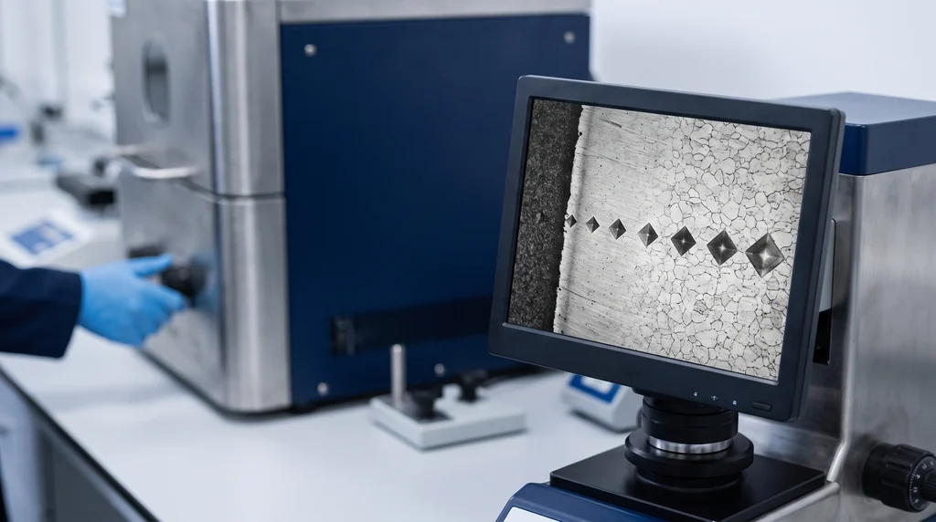
In the photo, the screen of a microhardness tester shows a row of Vickers indentations on a section of carburized steel: near the edge, where the case is harder, the indentations are smaller; in the core, they are larger. This profile is what defines the depth of the hardened case.
Effective case depth: CHD and NHD
Since hardness drops continuously, depth only makes sense with a criterion. ISO 18203:2026 (2nd edition, which replaced the 2016 edition and absorbed the former ISO 2639) brings together the criteria for hardened cases:
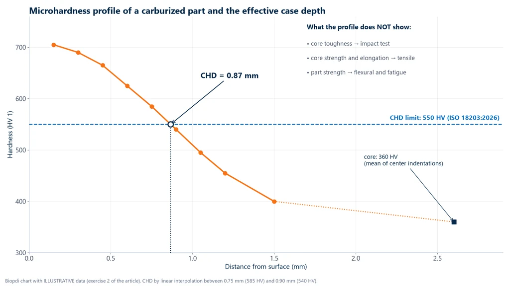
- CHD, carburized case: perpendicular distance from the surface to the point where the hardness equals 550 HV, measured by Vickers (ISO 6507-1) or by equivalent Knoop (ISO 4545-1). If the steel has more than 450 HV at three times the CHD, the parties may agree on a higher limit, in steps of 25 HV. Process control is covered in carburizing.
- NHD, nitrided case: distance to the point where the hardness is 50 HV above the core hardness. The limit is relative because the nitrided core varies with the steel and with the prior tempering; the profile and the white layer are covered in nitriding.
- SHD, surface hardening: the case hardened by induction or flame has its own criterion in the same standard, tied to the specified surface hardness.
Under the 2016 edition, profile forces range from HV 0.1 to HV 1 (0.9807 N to 9.807 N), with the first indentation at least 2.5 diagonals from the surface; the former ISO 2639 specified HV 1. According to the summary of changes published with the 2026 edition, it now indicates standard forces according to depth and an arbitration procedure. In any case, the part specification must state the criterion, the limit and the force, such as "CHD 550 HV 1 = 0.8 to 1.0 mm".
The graph below shows the profile from exercise 2, in HV 1: hardness starts at 705 HV at 0.15 mm from the surface, crosses 550 HV between 0.75 mm and 0.90 mm and reaches 360 HV in the core. Linear interpolation between the two neighboring readings gives CHD = 0.87 mm. On the right, the list of what this same profile does not tell you, the topic of the next subsection.
The desired step in depth is usually smaller than the minimum center-to-center distance. The solution is to arrange the indentations in a zigzag, in two lines parallel to the surface and offset laterally: each indentation sits at the right depth, and the actual distance to its neighbor is the diagonal of the offset, not the step. Exercise 2 shows the calculation.
What the hardness profile does not tell you about the part
The profile answers a single question: down to what depth the surface became hard. It is the right question for approving the heat treatment of a batch, but it is not the strength of the part. A carburized gear fails by bending fatigue at the tooth root, by contact fatigue on the flank or by fracture under shock, and none of these failure modes can be read from the profile:
- Core toughness decides whether the tooth breaks under a load peak. Two cores with the same hardness can have different toughness, depending on microstructure and grain size; it is measured by the impact test.
- Core yield strength, tensile strength and elongation come from the tensile test of a witness specimen, made of the same steel and processed in the same heat treatment cycle.
- The strength of the part as a structure, with the hard case over the tough core working together, shows up in the flexural test and the fatigue test. Retained austenite, intergranular oxidation and decarburization can keep hardness within range and still reduce fatigue life.
The profile, therefore, approves the case; the part is approved by the full set of tests. The section on what hardness does not measure, further below, applies the same reasoning to any material.
Phases, welded joints and Knoop
With forces from HV 0.01 to HV 0.1, the indentation is smaller than a grain and measures individual constituents: martensite, ferrite, pearlite, carbides, intermetallic phases. A single indentation does not represent the average hardness of the material, and the result must state which phase it fell in. The same method applies to ceramics, glasses and dental materials, with the precautions specific to brittle materials, which may crack at the corners of the indentation.
In coatings, such as electroplated hard chrome, thermal spray coatings and electroplated layers, the same thickness rule applies: the indentation must fit within the coating, with a thickness of at least 1.5 d. In a hard chrome of around 1,000 HV, an HV 0.5 indentation has d = √(0.1891 × 4.903 / 1,000) = 0.030 mm and requires at least 0.046 mm of coating. Coatings thinner than that are measured with a lower force, on a polished cross section or by instrumented indentation.
In welded joints, ISO 9015-1:2001 uses Vickers HV 5 or HV 10 in rows crossing the base metal, the heat-affected zone (HAZ) and the weld metal; the spacing and acceptance limits are summarized in the article on hardness testing. The hardness peak usually appears in the HAZ of hardenable steels, where the welding thermal cycle forms martensite.
The Knoop test (ISO 4545-1:2023) uses a diamond pyramid with a rhombic base, which leaves a narrow, elongated indentation, with the long diagonal about seven times the short one; only the long one is measured. For the same force, the Knoop indentation is much shallower than the Vickers one, which favors very thin cases and gradients measured at small distances. On the other hand, the Knoop value varies more with force, and HK and HV cannot be compared directly.
Converting HV to HRC, HB and tensile strength
There is no formula to convert HV to HRC: conversion is done with empirical tables, one for each material group, such as those in ISO 18265:2013 and ASTM E140-12B(2019)e1. HV measures the area of a pyramid indentation, HRC the depth of a cone, and the relationship between the two depends on how the material work-hardens. That is why the tables are built from comparative tests, material by material.
The table below shows rows from Table A.1 of ISO 18265:2013, which applies to unalloyed and low-alloy steels and cast steel, with the estimated tensile strength. ISO 18265 only tabulates Rm up to 650 HV (2,180 MPa); above that, the column is empty.
| HV | HRC | HB | Estimated Rm (MPa) |
|---|---|---|---|
| 250 | 22.2 | 238 | 800 |
| 300 | 29.8 | 285 | 965 |
| 360 | 36.6 | 342 | 1,155 |
| 400 | 40.8 | 380 | 1,290 |
| 450 | 45.3 | 428 | 1,455 |
| 500 | 49.1 | 475 | 1,630 |
| 550 | 52.3 | 523 | 1,810 |
| 600 | 55.2 | 570 | 1,995 |
| 640 | 57.3 | 608 | 2,145 |
| 700 | 60.1 | not tabulated | not tabulated |
The limits of conversion come from the standard itself. The table applies to the material group for which it was established: using the carbon steel table for an austenitic stainless steel, an aluminum or a brass gives a wrong number, and these materials have their own tables. The converted value is an estimate and does not prove compliance with a specification written in another scale; in the test report, it is identified as converted, together with the table used. And of all conversions, the one to tensile strength is the least reliable, because hardness is measured at one point on the surface while tensile strength is a property of the entire volume of the specimen.
Two recognized tables also do not agree with each other. For 640 HV, ISO 18265 gives 57.3 HRC and 2,145 MPa. The ASTM E140 table used in hardness of materials, interpolated between 613 HV (56 HRC, 2,158 MPa) and 653 HV (58 HRC, 2,330 MPa), gives the same 57.3 HRC, but 2,274 MPa. The conversion between hardness scales agrees; the strength estimate differs by 6% (exercise 4).
What hardness does not measure: why you need a universal testing machine as well
The Vickers test measures a single variable: the material's resistance to localized indentation at one point on the surface or cross-section. It is a fast, almost non-destructive measurement and an excellent process control tool. It tells you whether the heat treatment took, whether the case has the right depth, and whether this lot matches the last one. What it does not describe is how the material behaves under load up to failure, and that behavior is what designers use and what product standards require. The missing properties come from tests on a universal testing machine (tensile, compression, flexural and bend tests) and from the impact test.
The physical reason is that the indenter creates a state of confined compression in a small volume. The material around the indentation cannot yield freely, and no crack opens under compression. In a tensile test, the whole specimen is loaded: internal defects act as notches, and the material yields, work hardens, necks and fractures. Hardness sees the local resistance to yielding. It does not see ductility, stiffness, defects or the energy the material absorbs before it fractures. The table lists each property and the test that measures it:
| Property | Test that measures it | Equipment | Does hardness tell you? |
|---|---|---|---|
| Resistance to localized indentation | Vickers, Brinell, Rockwell | hardness tester | Yes: this is what it measures |
| Yield strength (ReH, Rp0.2) | tensile | universal testing machine with extensometer | No: the relationship changes with work hardening and heat treatment |
| Tensile strength (Rm) | tensile | universal testing machine | Only an estimate, the least reliable conversion |
| Elongation after fracture and reduction of area | tensile | universal testing machine | No |
| Modulus of elasticity | tensile with extensometer | universal testing machine with extensometer | No |
| Compressive strength | compression | universal testing machine with compression platens | No |
| Flexural strength and deflection | flexural | universal testing machine with flexural fixture | No |
| Bend ductility (cracking) | bend | universal testing machine with bend fixture | No |
| Impact toughness | Charpy or Izod | pendulum impact tester | No |
| Fatigue life | fatigue | cyclic testing machine | No |
Each row has its own article: tensile test, compression test, flexural test, bend test, impact test and ductility.
The hardness to strength correlation, and where it fails
In steels, hardness and tensile strength go together because both depend on the resistance to plastic flow. The textbook rule (Callister) is Rm ≈ 3.45 × HB, in MPa, and Table A.1 of ISO 18265 follows a similar ratio: 800/238 = 3.36 at 250 HV and 2,145/608 = 3.53 at 640 HV. The correlation is useful for screening and has three limits:
- It only applies to the material it was derived for. Cast iron, brass and aluminum have their own relationships, and the same factor applied to them is badly wrong.
- It estimates tensile strength, not yield strength. A cold-drawn steel and a normalized steel with the same tensile strength have different yield-to-tensile ratios, and hardness cannot tell them apart.
- It says nothing about ductility or toughness. Two steels with the same hardness can have very different elongation and impact energy, depending on microstructure, grain size and temper embrittlement.
Worked example: same hardness, different strengths
The clearest case is gray cast iron. Grade G4000 of SAE J431, a pearlitic gray iron used for diesel engine parts, liners and cylinders, is specified with a hardness of 217 to 269 HB and a minimum tensile strength of 276 MPa. A non-alloy steel at 238 HB, in the middle of that range, has an estimated tensile strength of 800 MPa according to ISO 18265, and the 3.45 × 238 rule gives 821 MPa. Anyone applying the steel rule to cast iron would estimate about 820 MPa for a material whose minimum is 276 MPa: almost three times as much.
The chart below compares the three numbers. The difference is not only in value: the steel yields, elongates and necks before fracturing, while gray iron fractures in a brittle manner, with practically no plastic deformation.
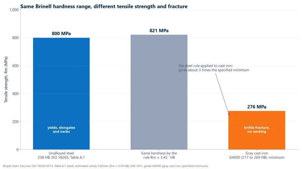
The explanation lies in the graphite. In gray iron, the graphite flakes act as internal cracks: in tension they open and concentrate stress, and the part fractures at a low load. Under the indenter, in confined compression, the flakes hardly matter, and the pearlitic matrix gives a steel-like hardness. Hardness sees the matrix; the tensile test sees the defects.
In the carburized part of exercise 2, the same reasoning appears in another form. The surface is at 705 HV, above the limit up to which ISO 18265 tabulates tensile strength: there is no estimated Rm for it. The core is at 360 HV, which the table converts to about 1,155 MPa. Neither number is "the strength of the part", which depends on the case and core working together, on geometry and on residual stresses. To find the core strength, a witness specimen of the same steel and heat treatment cycle is tensile tested: on a 10 mm diameter specimen (78.5 mm²), 1,155 MPa corresponds to about 91 kN. To find toughness, you run an impact test; for tooth strength, flexural and fatigue tests.
How to interpret a Vickers test result
Interpreting a Vickers result starts with checking that the numbers being compared were measured with the same test force, in the same region of the part and by the same criterion. The questions below come up often in the lab, in incoming inspection and in engineering, and almost all of them come from comparing numbers measured under different conditions.
Two labs measured the same part at HV 1 and HV 10 and got different values. Is one of them wrong?
Not necessarily. In a homogeneous, well-prepared material, the two should be close; in a material with a case, a gradient or coarse phases, they measure different volumes. The HV 10 indentation is about three times larger than the HV 1 indentation and averages over a larger region, which may include softer material below the surface. At low forces, the indentation size effect and specimen preparation also push the reading up. Only compare results at the same force, and the specification must state which force.
The microhardness of the case came out lower than the surface hardness specified in HRC. Is the case soft?
First, check whether the comparison is even possible. HRC and HV measure different things and are only linked through a table. Then check where the indentation landed: the first indentation of a profile is at least 2.5 diagonals from the edge, and the surface may have a decarburized layer or retained austenite, which gives lower hardness just below the surface. A surface hardness specified in HRC is checked in HRC (or on the superficial N scale) on the surface itself; the HV profile checks the depth.
The two diagonals differ by 8%. Is the result valid?
The value can be calculated from the mean, but a difference above 5% goes in the test report. Common causes are a surface tilted relative to the indenter (a poorly mounted specimen or an unlevel stage), an anisotropic material such as rolled sheet, or an indentation near a phase boundary. If the cause is specimen seating, correct it and repeat.
Can I accept a lot of steel based on hardness?
It depends on what the specification requires. If it calls for a hardness range, hardness accepts that requirement. If it calls for yield strength, tensile strength, elongation or impact energy, as standards for structural steel, reinforcing bars and bolts do, those requirements can only be accepted through the corresponding tests. Converted hardness does not replace the tensile test.
The profile gave a CHD within tolerance. Is the part accepted?
The case is. Accepting the part also requires surface hardness, core hardness, metallography of the case (retained austenite, intergranular oxidation, carbide network) and, depending on the specification, core properties from a tensile test on a witness specimen. The CHD only answers the depth question.
Worked exercises
The four exercises apply the HV formula, the thickness and spacing rules, the CHD criterion and the conversion tables to common laboratory cases.
1. HV from the diagonals. A steel sheet was tested at HV 10 (F = 98.07 N), and the measured diagonals were d1 = 0.300 mm and d2 = 0.306 mm. Calculate the hardness and check the part.
- Mean: d = (0.300 + 0.306)/2 = 0.303 mm; d² = 0.091809 mm².
- Hardness: HV = 0.1891 × 98.07 / 0.091809 = 18.545 / 0.091809 = 202 HV 10.
- Difference between diagonals: 0.006 / 0.303 = 2.0%, below 5%.
- Minimum thickness: 1.5 × 0.303 = 0.45 mm. Indentation depth: 0.303 / 7 = 0.043 mm.
- Position: in steel, the next indentation must be at least 3 × 0.303 = 0.91 mm away, and the edge at least 2.5 × 0.303 = 0.76 mm away.
2. Microhardness profile and CHD. A carburized gear was sectioned, mounted and polished, and the profile was measured at HV 1 (F = 9.807 N), with these results (illustrative data):
| Distance from surface (mm) | HV 1 | Distance from surface (mm) | HV 1 |
|---|---|---|---|
| 0.15 | 705 | 0.90 | 540 |
| 0.30 | 690 | 1.05 | 495 |
| 0.45 | 665 | 1.20 | 455 |
| 0.60 | 625 | 1.50 | 400 |
| 0.75 | 585 | core | 360 |
- 550 HV lies between 0.75 mm (585 HV) and 0.90 mm (540 HV).
- Linear interpolation: CHD = 0.75 + (585 − 550)/(585 − 540) × 0.15 = 0.75 + 0.778 × 0.15 = 0.87 mm.
- Standard limit: at three times the CHD, about 2.6 mm, the core is at 360 HV, below 450 HV, so the 550 HV limit applies.
- First indentation: at 705 HV, d = √(0.1891 × 9.807 / 705) = √0.002631 = 0.0513 mm, and 2.5 d = 0.128 mm. The first reading, at 0.15 mm, complies.
- Spacing: near 550 HV, d = √(0.1891 × 9.807 / 540) = 0.0586 mm and 3 d = 0.176 mm. A 0.15 mm step in a straight line does not comply. In a staggered (zigzag) pattern, with the two rows 0.20 mm apart laterally, the distance between neighbors is √(0.15² + 0.20²) = 0.25 mm, greater than 3 d even in the core (d = 0.0718 mm, 3 d = 0.215 mm).
The result is written with the criterion and the force: CHD 550 HV 1 = 0.87 mm. The normative interpolation method is in Annex A of ISO 18203:2026.
3. Choosing the test force. (a) Can a 0.50 mm steel strip at about 200 HV be tested at HV 30? (b) Can a nitrided case at about 900 HV be measured at HV 0.1?
- (a) At HV 30 (294.2 N): d = √(0.1891 × 294.2 / 200) = √0.2782 = 0.527 mm, and 1.5 d = 0.79 mm, more than the 0.50 mm strip: does not comply. At HV 10: d = 0.304 mm and 1.5 d = 0.46 mm: complies, just barely. At HV 5 (49.03 N): d = 0.215 mm and 1.5 d = 0.32 mm, with margin.
- (b) At HV 0.1 (0.9807 N): d = √(0.1891 × 0.9807 / 900) = √0.0002061 = 0.0144 mm, below 0.020 mm: outside the scope of ISO 6507-1. At HV 0.5 (4.903 N): d = √0.0010302 = 0.0321 mm, valid. What remains is to check that the indentation fits within the case: the depth is 0.0321/7 = 0.005 mm.
4. Converting 640 HV 30 and the size of the error. A test report gives 640 HV 30 for a hardened low-alloy steel. Estimate HRC and Rm.
- ISO 18265:2013, Table A.1: 640 HV is equivalent to 57.3 HRC, 608 HB and an Rm of 2,145 MPa.
- Callister's rule: 3.45 × 608 = 2,098 MPa, 2.2% below ISO.
- ASTM E140, interpolated between 613 HV (56 HRC, 2,158 MPa) and 653 HV (58 HRC, 2,330 MPa): fraction (640 − 613)/(653 − 613) = 0.675; HRC = 56 + 0.675 × 2 = 57.3; Rm = 2,158 + 0.675 × 172 = 2,274 MPa.
- Reading: the estimated HRC agrees in both tables; Rm ranges from 2,098 to 2,274 MPa, 176 MPa between the lowest and highest. For a design value, a tensile test is mandatory. On a 6 mm diameter specimen (28.3 mm²), 2,274 MPa would give about 64 kN.
Common mistakes in Vickers and microhardness testing
The most frequent mistakes in Vickers testing involve units, a poorly chosen test force, indentation position and interpretation of the number. The list collects the ones that show up in test reports, specifications and reference texts:
- Using d in micrometers in the formula. HV = 0.1891·F/d² requires d in millimeters: 40 µm is 0.040 mm.
- Confusing the face area with the projected area. Vickers divides by the area of the faces; Knoop, by the projected area. Swapping one for the other changes the number.
- Saying microhardness is "below 10 gf" or that Vickers "ranges from 1 to 120 kgf". Under ISO 6507-1:2023, microhardness runs from HV 0.001 to below HV 0.2, low-force hardness from HV 0.2 to below HV 5, and the macro range starts at HV 5. Tests at HV 1 to HV 3 are therefore low-force tests, and the 1 kgf (1,000 gf) limit is the microindentation limit in ASTM E384.
- Reporting the result without the force. "580 HV" without the force cannot be compared, especially in microhardness.
- Low force on a hard material. A diagonal below 0.020 mm is outside the scope of the standard (exercise 3).
- Indentation near the edge, near another indentation or on a thin part. The reading changes without warning; a mark on the back side invalidates the test.
- Preparation that heats or work hardens the specimen. Dry cutting can temper a hardened steel; coarse grinding pushes up the microhardness reading.
- Straight-line profile with a step smaller than 3 d. Each indentation lands in the work-hardened zone of the previous one; use a staggered (zigzag) pattern.
- Converting with the wrong table. The carbon steel table does not apply to austenitic stainless steel, aluminum, brass or cast iron.
- Estimating the strength of a carburized part from its surface hardness. The surface does not represent the volume, and above 650 HV ISO 18265 does not even tabulate Rm.
- Accepting material on hardness alone. Yield strength, elongation, reduction of area, modulus and toughness come from tensile, flexural, bend and impact tests.
- Citing a withdrawn standard, such as ISO 6507-1:2018 or ISO 2639, now superseded by ISO 18203:2026.
Universal testing machine for the tests that complement hardness
Biopdi does not manufacture hardness testers. We manufacture the metallography equipment that prepares the sample for microhardness testing, and the universal testing machine (UTM) that measures what hardness cannot. The Biopdi M2 line is electromechanical, with class 1 load cells per ABNT NBR ISO 7500-1:2023 (the Brazilian adoption of ISO 7500-1), extensometers and the BioLab software. It runs the tensile, compression, flexural and bend tests in the table above, and the report includes the complete stress-strain curve. The panel below shows the machine, what each part does and the fixtures used in these tests.
The universal testing machine in the tests that complement hardness
The M2 line has single-column models, from 200 N to 10 kN, and dual-column models, from 5 kN to 1,000 kN. Each part of the machine has a role in the tests that hardness cannot replace:

- Moving crosshead applies tension, compression or bending at the speed set by the standard
- Load cell, class 1: force for yield, tensile and flexural strength
- Wedge grips for the witness specimen
- Extensometer for modulus, Rp0.2 and elongation
- Fixtures for compression, flexural and bend tests
- BioLab software plots the curve and calculates yield strength, tensile strength and elongation
Fixtures for the complementary tests
The fixtures below are mounted on the same machine, depending on the test and the specimen:
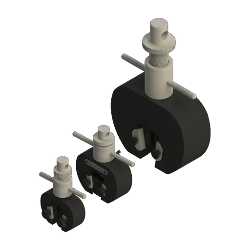
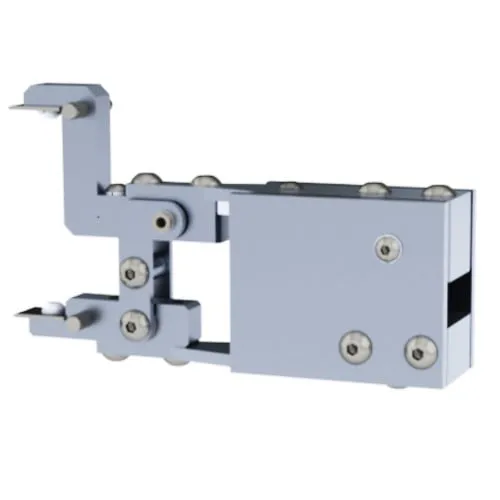
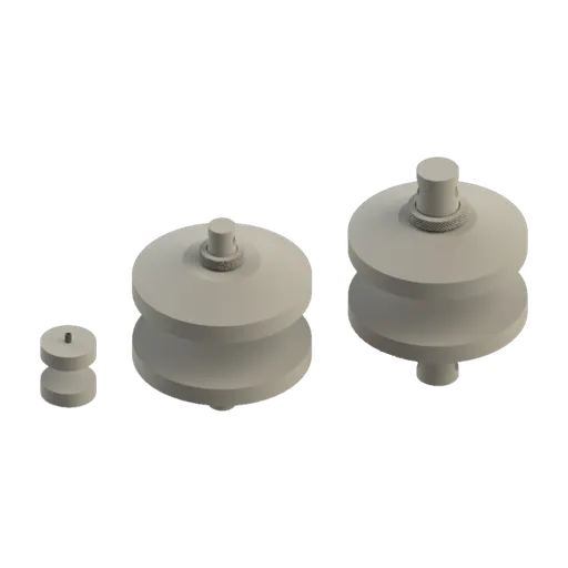
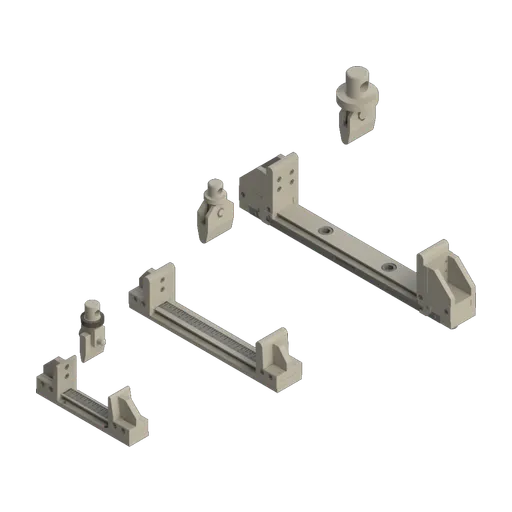
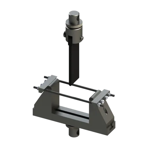
Capacity is chosen by the maximum expected force. A 10 mm diameter witness specimen of a carburized core of about 1,155 MPa breaks at around 91 kN, which calls for the dual-column machine of 100 to 200 kN, in the 150 or 200 kN version to leave a margin. Annealed and normalized steels in smaller specimens fall within the range of the 5 to 50 kN machine. The BioLab software builds the report with the curve and the results, and the tensile testing standard for metals is explained in the guide to ASTM E8 and ISO 6892-1. Other configurations are on the universal testing machine page, and you can request a quote for the materials your lab tests.
Vickers and microhardness test standards
The ISO Vickers method has three parts: test method, verification of the testing machine and calibration of the reference blocks. The table lists the standards cited in this article. The current editions of the ISO standards were checked on October 1, 2026 in the iso.org catalog; the ASTM and ABNT editions on September 30, 2026 in their respective catalogs:
| Standard | Scope | Edition |
|---|---|---|
| ISO 6507-1 | Vickers, test method: macro, low-force and microhardness | 2023 |
| ABNT NBR ISO 6507-1 | Brazilian adoption of ISO 6507-1 | 2026 |
| ISO 6507-2 and ISO 6507-3 | verification of the testing machine and calibration of reference blocks | 2018 |
| ASTM E92 | Vickers and Knoop hardness of metallic materials | E92-26 |
| ASTM E384 | microindentation hardness, from 1 gf to 1,000 gf | E384-22 |
| ISO 4545-1 | Knoop, test method | 2023 |
| ISO 14577-1 | instrumented indentation, below a diagonal of 0.020 mm | 2026 |
| ISO 18203 | depth of hardened layers (CHD, SHD, NHD); absorbed ISO 2639 | 2026 |
| ISO 18265 | conversion of hardness values | 2013 |
| ASTM E140 | hardness conversion tables for metals | E140-12B(2019)e1 |
| ISO 9015-1 | hardness testing of arc-welded joints | 2001 |
ISO 6507-1:2023 replaced the 2018 edition, and ABNT published the new NBR ISO 6507-1 in Brazil in February 2026, replacing the 2019 edition. ISO 6507-2 and 6507-3, both from 2018, remain current, reviewed and confirmed in 2023 and 2022, respectively; ISO 18265:2013 was confirmed in 2024 and ISO 9015-1:2001 in 2022. ISO 18203:2016 and ISO 2639:2002 have been withdrawn.
Other tests and technical references
Tests performed on the Biopdi universal testing machine



















Related technical references
Rockwell hardness test: how it works, HRC and HRB scales and ISO 6508-1
Rockwell hardness test: permanent indentation depth becomes HR = N − h/S. HRC and HRBW scales, ISO 6508-1:2023, and what hardness does not measure.
Coefficient of friction: what it is, formula, table and test (ASTM D1894)
The coefficient of friction (μ) is the ratio of the friction force to the normal force between two surfaces. See the formula, static and kinetic friction, the inclined plane, a table of values, solved exercises and film testing per ASTM D1894 and ISO 8295.
Hardness test: types, procedure and standards (Brinell, Rockwell, Vickers and Shore)
A hardness test presses a standardized indenter into the part under controlled force and dwell time, then measures the indentation or its depth. See the types, the step-by-step procedure for each method, minimum thickness and spacing, hardness tester verification and standards.
Frequently asked questions
What is the Vickers hardness test?
It is an indentation test in which a square-based diamond pyramid, with 136° between opposite faces, is pressed into the material with a known force. Both diagonals of the indentation are measured and HV = 0.1891·F/d² is calculated, with F in newtons and d in millimeters. The method is specified in ISO 6507-1:2023 and ASTM E92-26.
What does Vickers mean?
It is the name of the British company Vickers. The engineers R. L. Smith and G. E. Sandland, who worked for it, published the method in 1922 in the Proceedings of the Institution of Mechanical Engineers. The symbol HV comes from "hardness Vickers".
How is the Vickers hardness test performed?
The surface is prepared smooth and clean, and polished for microhardness. The force is applied without shock, reaching its full value in 2 to 8 s, and held for 10 to 15 s. After the force is removed, both diagonals are measured under the microscope and HV is calculated from their mean, recording the force in the notation, as in 640 HV 30.
How do you convert HV hardness to HRC?
Using the table for the material group in ISO 18265:2013 or ASTM E140. For unalloyed and low-alloy steel, 300 HV corresponds to about 29.8 HRC, 400 HV to 40.8 HRC and 500 HV to 49.1 HRC. It is an estimate: it does not prove conformity with a specification given in HRC and does not apply to another material group.
What is Vickers microhardness?
It is the Vickers test with a force from 0.009807 N to less than 1.961 N (from HV 0.001 to less than HV 0.2), per ISO 6507-1:2023. The indentation is tens of micrometers across and measures microstructural phases, coatings and the profiles of carburized or nitrided case layers, on a mounted and polished sample.
What is a microhardness test?
It is an indentation hardness test with a very low force, which leaves an indentation tens of micrometers across, measured under the microscope. Per ISO 6507-1:2023, Vickers microhardness is below 1.961 N (HV 0.2); per ASTM E384-22, microindentation ranges from 1 gf to 1,000 gf. It is used to measure phases, case layers, coatings and very thin parts.
What are the main tests used to measure microhardness?
The two main ones are Vickers, with a square-based pyramid (ISO 6507-1:2023), and Knoop, with an elongated pyramid (ISO 4545-1:2023); ASTM E384-22 covers both. Below a diagonal of 0.020 mm, instrumented indentation per ISO 14577-1:2026 is used, which records force and depth instead of measuring the indentation.
What is the difference between Vickers hardness and Vickers microhardness?
The indenter and the formula are the same; the force changes. Macro Vickers uses 49.03 N or more (HV 5 or more) and measures average hardness; microhardness is below 1.961 N and measures regions of a few micrometers. Between the two lies the low-force range, from HV 0.2 to less than HV 5.
What is the Vickers hardness scale?
It is a single continuous scale, with no sub-scales, that runs from soft metals, at a few tens of HV, to hard metals above 1,500 HV. This is possible because the pyramid indentations are geometrically similar at any force, and the diamond can measure any metal.
What is the minimum sample thickness in the Vickers test?
At least 1.5 times the indentation diagonal, with no visible mark on the back (ISO 6507-1:2023). An HV 10 indentation of 0.30 mm requires a thickness of about 0.45 mm; in a case layer, the rule applies to the layer thickness.
What is the minimum spacing between Vickers indentations?
In steel, copper and copper alloys, 3 diagonals between centers and 2.5 diagonals from the center to the edge; in light metals, lead, tin and their alloys, 6 and 3 diagonals (ISO 6507-1:2023). In a microhardness profile with a smaller step than this, the indentations are placed in a zigzag.
What are the advantages and disadvantages of the Vickers test?
The advantages are the single scale, from soft to hard metal, with only one diamond indenter, and the small indentation, which allows testing thin parts, case layers and phases. The disadvantages are the need for a prepared surface, polished for microhardness, and the optical measurement of the diagonals, which is slower than the direct reading of Rockwell.
How is carburized case depth measured with microhardness?
With a Vickers hardness profile on a polished cross section, from the surface to the core, usually between HV 0.1 and HV 1. The CHD is the distance at which the profile crosses 550 HV, per ISO 18203:2026, obtained by interpolation between the two neighboring readings. For nitriding, the limit is the core hardness plus 50 HV.
What is the difference between Vickers and Knoop?
Knoop uses a rhombic-based pyramid that leaves an elongated, shallower indentation, with the long diagonal about seven times the short one, well suited to very thin layers. The Knoop value varies more with force than Vickers does, and HK and HV cannot be compared directly. Knoop is specified in ISO 4545-1:2023 and ASTM E92.
Does Vickers hardness replace the tensile test?
No. Hardness measures a single variable, the resistance to localized indentation. Tensile strength can be estimated from a table, with uncertainty, but yield strength, elongation, reduction of area and modulus of elasticity only come from the tensile test, and toughness from the impact test. A gray cast iron of 217 to 269 HB has a minimum tensile strength of 276 MPa, about one third of that of a steel of the same hardness.
What is the Shore hardness test?
It is a hardness test for rubbers and plastics, performed with a durometer that has a spring-loaded indenter, with readings from 0 to 100 (ASTM D2240): scale A is for rubbers and soft elastomers, scale D for rigid plastics. It does not apply to metals and cannot be converted to HV; the comparison between methods is in the article on hardness of materials.