
A load cell is the electromechanical sensor (force transducer) that converts force or weight into an electrical signal: the force deforms a metal body, strain gauges bonded to it change resistance, and a Wheatstone bridge delivers a proportional voltage, typically 2 mV per volt of excitation at rated capacity. Powered with 10 V, the load cell delivers 20 mV at rated capacity and 12 mV at 60% of it. It is the load cell that weighs on the scale, measures the fill level of the silo and, in the universal testing machine (UTM), records the force at every point of the curve. This article explains the principle, the types, the datasheet and the wiring, and then covers what the usual search does not: the load cell of the testing machine, the class under ISO 7500-1 (ABNT NBR ISO 7500-1 in Brazil), the verified range and the choice of capacity.
In short:
- Signal: V = S · Vexc · F / Fnom, where S is the sensitivity in mV/V. With 2 mV/V and 10 V, rated capacity gives 20 mV.
- Types: chosen by the direction of the force, the capacity and the space: S-type for in-line tension and compression, column for high compression, pancake for low height, single point and beam for weighing.
- In the testing machine: class 1 under ABNT NBR ISO 7500-1 belongs to the machine's force measuring system, not to the load cell: it limits the relative indication error to ±1% of the force, only within the verified range, which has a lower limit, and it does not include the calibration uncertainty.
What a load cell is and what it is used for
A load cell is a force transducer: it receives a mechanical quantity and returns an electrical one, proportional to it. In Portuguese it is called célula de carga; commercially, it also appears as a weight sensor or force sensor. The most common construction, which this article covers, has two parts. The first is the spring element, a block of alloy steel, stainless steel or aluminum machined so that the force produces measurable strain at a chosen point. The second are the resistance strain gauges, thin metal grids bonded exactly at that point, whose electrical resistance changes when the metal under them stretches or shortens.
Load cells based on other principles exist. The hydraulic load cell measures the pressure of a confined fluid under a piston and has no electrical part, which favors it in hazardous areas; the pneumatic one balances the force with air pressure; the vibrating wire one reads the change in frequency of a tensioned wire; the piezoelectric one generates electrical charge under force and is used for dynamic measurement, because the signal decays when the force stays constant. The strain gauge load cell dominates industry and the laboratory through its combination of cost, accuracy and stability, and it is the subject of the rest of this article.
The spring element always works in the elastic regime: the deformation disappears when the force is removed, as explained in the article on elastic deformation. In this regime Hooke's law applies, and the strain at the strain gauge location is proportional to the force. It is this proportionality that makes the load cell signal a measure of force. The design of the element sets the strain at rated capacity at about 1,000 µm/m (0.1%), far from the yield of the metal, so that the load cell returns to zero after each load.
The function is always the same: measure force or weight and deliver a signal to an indicator, a PLC or software. What changes is the place: bench scales and truck scales, silos and tanks, dosing and filling machines, onboard weighing on trucks and agricultural machinery, load limiters on cranes and overhead cranes, medical equipment, presses, test benches and universal testing machines. Two dates frame the technology: the bridge used for the reading was made known by Charles Wheatstone in 1843, and the bonded resistance strain gauge was created in 1938, independently, by Edward Simmons at Caltech and Arthur Ruge at MIT.
How it works: strain gauge, Wheatstone bridge and signal in mV/V
A load cell works in three steps: the strain changes the resistance of the strain gauge, the bridge turns that change into a voltage, and the voltage is read per volt of supply. Each step has a simple calculation, and together they explain the number that appears on every datasheet, the mV/V.
The strain gauge: ΔR/R = k · ε
When the metal grid of the strain gauge is stretched, the wires become longer and thinner, and the resistance rises; when it is compressed, the resistance falls. The relationship is linear: ΔR/R = k · ε, where ε is the strain (m/m) and k is the gauge factor, dimensionless, close to 2 for the usual metal alloys. With ε = 1,000 µm/m and k = 2, the resistance changes by 0.2%. On a 350 Ω strain gauge, that is 0.7 Ω. Such a small change cannot be measured well with an ordinary ohmmeter, which is why the load cell uses a bridge.
The full Wheatstone bridge
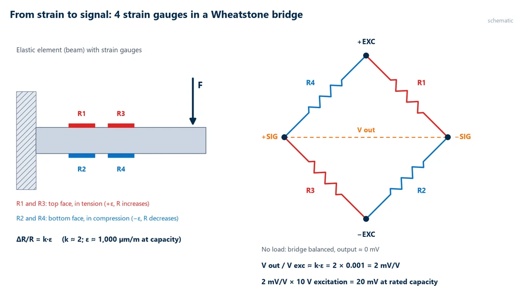
The Wheatstone bridge has four resistors connected in a diamond. Two opposite corners receive the supply voltage, called the excitation (+EXC and −EXC); the other two are the output (+SIG and −SIG). With all four resistors equal, the bridge is balanced and the output is zero. In a load cell, the four resistors are active strain gauges: two sit in a region in tension and two in a region in compression, connected so that gauges of the same sign occupy opposite arms. This way the four effects add up instead of canceling, and the output is approximately:
Vout / Vexc ≈ k · ε
The diagram below shows the arrangement on a cantilever beam, the easiest geometry to visualize. The force at the free end puts the top face in tension, where R1 and R3 sit, and compresses the bottom face, where R2 and R4 sit. In the bridge, R1 and R3 occupy opposite arms, and R2 and R4 the other two; the calculation at the bottom shows where the value of 2 mV/V comes from.
The full bridge has a second advantage, as important as sensitivity: temperature compensation. If the load cell heats up, the four strain gauges change resistance in the same proportion, and the bridge stays balanced. What unbalances the bridge is only the difference between arms, which comes from the force. Additional resistors, trimmed at the factory, correct the zero, the thermal drift of the zero and that of the sensitivity.
The bridge also tells the direction of the force. When the force changes from tension to compression, the strain gauges in tension go into compression and vice versa, and the output changes polarity: the same load cell reads both directions, with a positive sign in one and a negative sign in the other. This is what allows an S-type or pancake load cell to measure tension and compression in the same setup.
Why the market talks about 2 mV/V
The sensitivity of a load cell is the output at rated capacity divided by the excitation voltage, in mV/V. With k ≈ 2 and the element designed for ε ≈ 1,000 µm/m at capacity, the bridge gives k · ε = 2 × 0.001 = 0.002 V/V, or 2 mV/V. That is why this value appears on so many datasheets, such as that of the HBM S9M S-type load cell. In column load cells, two strain gauges are along the direction of the force and two are transverse, where the strain is only the Poisson strain (ν · ε); the output drops to k · ε · (1 + ν) / 2, and the design compensates with more axial strain.
Since the output is proportional to the excitation, the signal at any force is V = S · Vexc · F / Fnom. The table shows the signal of a 2 mV/V load cell with the two most common excitations. It makes clear that the load cell delivers only a few millivolts: at 10% of capacity, with 5 V, that is 1.0 mV.
| Force, in % of capacity | 5 V excitation | 10 V excitation |
|---|---|---|
| 10% | 1.0 mV | 2.0 mV |
| 20% | 2.0 mV | 4.0 mV |
| 60% | 6.0 mV | 12.0 mV |
| 100% | 10.0 mV | 20.0 mV |
| 150% (typical limit load) | 15.0 mV | 30.0 mV |
Two practical consequences follow. First, the signal changes with the excitation: if the supply varies by 1%, the reading varies by 1%, so the excitation must be stable and, with long cables, measured at the load cell itself, as shown in the wiring section. Second, millivolt signals are sensitive to electrical noise, which makes a shielded cable, correct grounding and a good-quality amplifier mandatory.
Types of load cell
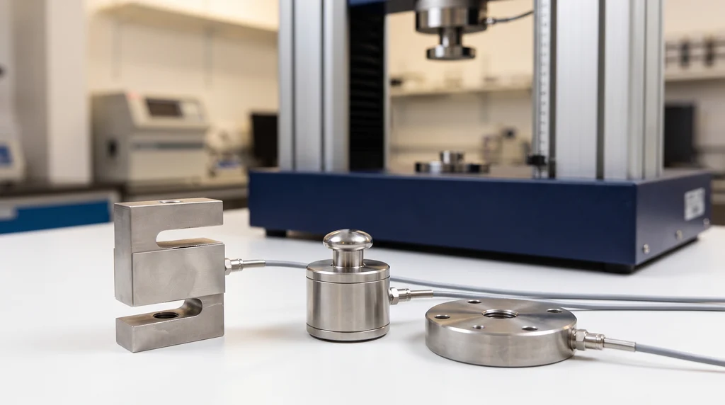
Load cell types differ by the geometry of the spring element; the electrical principle is the same in all of them. Each geometry concentrates the strain in its own way and serves a direction of force, a capacity range and a mounting space. In the photo, three common load cells: on the left, the S-type load cell, which works in tension and compression through the threaded holes at its ends; in the middle, the compression load cell with a domed button, which receives the load on top; on the right, the pancake load cell, bolted at its rim and loaded through the central hole.
The most widely used types are these:
- S-type (and Z-type): S-shaped body with threads at both ends. The force enters in line through one thread and leaves through the other, in tension or compression; it is the most common tension load cell. It appears in hanging scales, conversion of mechanical scales, test benches and low-capacity testing machines. Brazilian manufacturers offer 5 to 5,000 kg; the HBM S9M ranges from 500 N to 50 kN.
- Column (compression): cylinder loaded along its axis, usually through a domed button that centers the force. It measures mainly compression and reaches hundreds of tonnes: truck scales, silos, presses. In the rocker column version, the domed ends bring the column back upright when the platform shifts; in the canister version, the body is hermetically sealed in stainless steel.
- Pancake: low disc, fixed at the rim and loaded at the center, in tension and compression. It provides high capacity in little height and is common in testing machines and presses. The version with a hollow center, called a donut, measures the force in bolts and tie rods that pass through it.
- Single point: aluminum block with a binocular hole, compensated so that the reading does not depend on where the load falls on the platter. It is the load cell of the bench scale and the filling machine, typically 5 to 500 kg.
- Beam: beam fixed at one end and loaded at the other. In the bending beam, the strain gauges read bending; in the shear beam (single or double ended), they sit at 45° to the load axis, on a recessed web, and read shear, which makes the reading less sensitive to the load position. Floor platforms, tanks and silos use beams from 250 kg to tens of tonnes.
- Load pin: instrumented shaft that replaces the pin of a joint, in cranes, pulleys, shackles and sheave blocks. It measures the force passing through the pin, by shear, without adding a part to the structure.
- Button: miniature compression cylinder for small spaces, mounted inside fixtures.
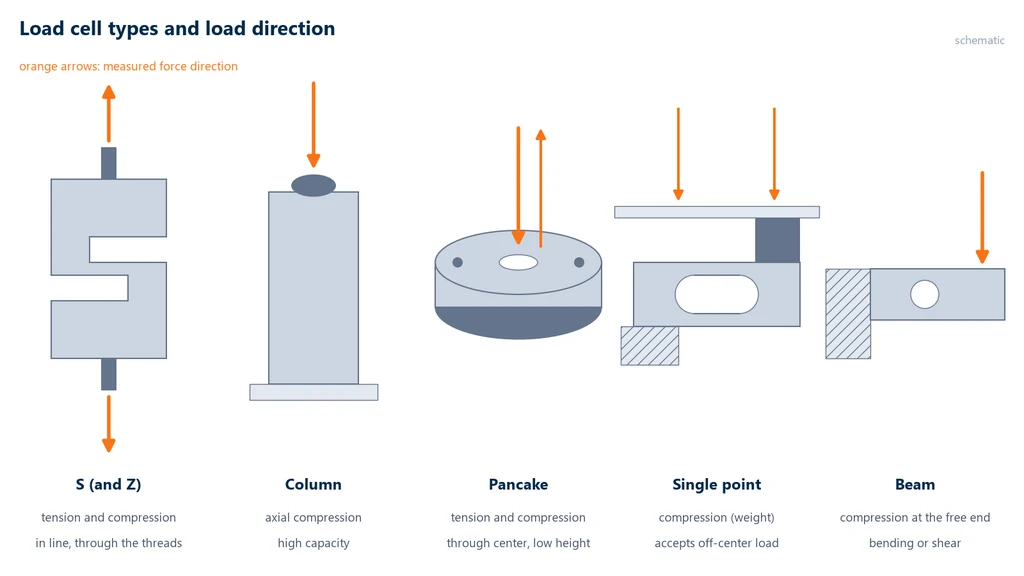
The diagram below compares five of these geometries side by side, with the orange arrow in the direction of the force each one measures: on the two that work in tension and compression (S-type and pancake), the arrows point both ways; on the weighing ones (single point and beam), the force is vertical and downward.
The table summarizes where each type is used. The capacity ranges come from manufacturers' catalogs and serve as an order of magnitude:
| Type | Force measured | Typical range | Where it is used |
|---|---|---|---|
| S-type and Z-type | tension and compression | 5 to 5,000 kg | hanging scale, test bench, testing machine |
| Column | compression | up to hundreds of t | truck scale, silo, press |
| Pancake and donut | tension and compression | high, in little height | testing machine, press, tie rod |
| Single point | compression (weight) | 5 to 500 kg | bench scale, filling machine |
| Beam (bending and shear) | compression (weight) | 250 kg to 50 t | platform, tank, silo |
In the universal testing machine, the load cell sits in series with the test specimen, between the crosshead and the grip or platen, and must measure in both directions, because the same machine performs tensile and compression tests. That is why the geometries used there are the S-type, at low capacities, and the tension-compression pancake or column, at high capacities. A weighing load cell, single point or beam, is not suited to this use.
Load cell specifications: how to read the datasheet
The datasheet expresses the quality of a load cell in numbers, and almost all of them are given as a percentage of full scale (FS), that is, of the output at rated capacity. This matters: 0.02% FS on a 10 kN load cell is 2 N, whether the measured force is 10 kN or 500 N. These are the items that drive the choice:
- Rated capacity (Emax): the highest force for which the load cell is specified. It ranges from grams to hundreds of tonnes.
- Sensitivity and its tolerance: the output in mV/V at capacity, usually 2 mV/V, and how far the actual load cell deviates from the nominal value. The exact value comes on the certificate of each individual load cell, and that is the value used to set up the indicator.
- Nonlinearity: the largest deviation between the actual load curve and the straight line joining zero to capacity, in % FS.
- Hysteresis: the difference between the reading with increasing load and the reading with decreasing load at the same point, in % FS. It matters in tests that include unloading, such as the loading and unloading cycles used to measure the modulus of elasticity.
- Repeatability: the scatter between readings of the same force, repeated under the same conditions.
- Creep: the drift of the signal under constant force, usually measured over 30 minutes. It matters in long tests, such as creep and relaxation tests.
- Temperature effect on zero and on sensitivity, in % per 10 K, and the compensated temperature range.
- Safe load limit and breaking load: the safe load limit is the highest force the load cell withstands without losing its calibration; the breaking load is mechanical failure. HBM states 150% and 300% of capacity for the Z6 load cell.
- Input resistance and excitation: 350 Ω is the most common bridge value; the recommended excitation is between 5 and 10 V, with a maximum of 15 V on the Z6.
- Ingress protection (IP) rating and sealing: from IP65 to IP69K in catalogs. Resin or epoxy potting protects against ordinary moisture; hermetic sealing, with a welded stainless steel body (IP68 or higher), is the choice for washdown and aggressive environments. For explosive atmospheres there are versions certified for hazardous areas (ATEX in Europe; in Brazil, Ex certification under Inmetro, the Brazilian metrology and certification institute).
The table gathers the typical values cited, with the source of each one:
| Specification | Typical value | Source |
|---|---|---|
| Nominal sensitivity | 2 mV/V | HBM S9M |
| Accuracy of strain gauge load cells | 0.25% to 0.03% FS | Omega |
| Safe load limit / breaking load | 150% / 300% of Emax | HBM Z6 |
| Input resistance | 350 Ω | HBM Z6; Interface |
| Excitation | 5 to 10 V (max. 15 V) | HBM Z6 |
| Creep of a C3 load cell over 30 min | 0.0245% of rated output | OIML R 60 |
The datasheet also gives an accuracy class, and this is the biggest source of confusion in the field: there are three different class systems, for three different things. The "How to interpret" section comes back to this point in detail.
How to wire a load cell: 4-wire, 6-wire and signal conditioner
A load cell connects to the indicator with 4 or 6 wires, and the choice depends on the cable length. A 4-wire load cell has two excitation wires (+EXC and −EXC) and two signal wires (+SIG and −SIG). A common color code, used by Interface, is red for +EXC, black for −EXC, white for +SIG and green for −SIG, but there is no universal standard: the correct wiring is the one on the certificate or datasheet of the load cell itself. A braided shield usually runs with the cable and is connected to ground on the instrument side.
The problem with 4 wires is the cable. The excitation reaches the bridge after passing through two conductors with resistance, and part of the voltage is lost along the way. Since the output is proportional to the excitation that reaches the bridge, the load cell delivers less signal than it was calibrated for. Interface estimates the loss at about 0.37% of sensitivity for every 10 feet (about 3 m) of 28 AWG cable. The resistance of copper also changes with temperature, so the loss varies throughout the day.
A 6-wire load cell solves this with two extra conductors, +SEN and −SEN (sense), connected to the excitation right at the bridge. No significant current flows through them, so they measure the voltage that actually reaches the load cell, and the signal conditioner corrects the excitation or the reading. The voltage drop in the cable no longer matters, including its variation with temperature. The resulting rule:
- On a 4-wire load cell, the manufacturer compensates the assembly with the factory cable. Do not cut or splice that cable: its length is part of the calibration.
- With a long cable, or when the load cell has to be installed far from the instrument, use 6 wires with sense. Massload suggests 6 wires above about 20 m of cable.
Platform scales, tanks and silos use three or four load cells under the same structure, wired in parallel in a junction box and read as a single load cell. Since each load cell has a slightly different sensitivity, the box has adjustments to equalize the outputs; without this adjustment, the same mass gives different readings depending on the corner of the platform where it is placed, the so-called corner error. A universal testing machine has no such arrangement: the force passes through a single load cell, in series with the test specimen.
The signal conditioner, or amplifier, completes the chain: it supplies stable excitation, amplifies the millivolts to the range of the analog-to-digital converter, filters noise and applies zero (tare) and the calibration factor. In Arduino prototypes this role is often played by an HX711 module, a 24-bit converter with a built-in amplifier; it is enough for a simple scale, but it has neither the stability nor the traceability of an industrial signal conditioner. In a universal testing machine, this function is handled by the data acquisition electronics, which deliver the force to the software together with the crosshead displacement and, when present, the strain read by the testing extensometer.
The load cell in the universal testing machine
The load cell of the universal testing machine is the force link for everything that is calculated. Ultimate tensile strength is Fmax / S0, yield strength comes from a force read at the yield plateau or at the departure from the straight line, and every point of the stress-strain curve is a load cell force divided by the cross-sectional area of the test specimen. A 2% error in force becomes a 2% error in ultimate tensile strength, with nothing in the curve to give it away.
That is why testing standards are not satisfied with the load cell specification: they require the force-measuring system of the machine to be verified. In Brazil, the document is ABNT NBR ISO 7500-1:2023, the Brazilian adoption of ISO 7500-1:2018. It specifies the calibration and verification of tension and compression testing machines and assigns each force range to a class. What is verified is the complete system (load cell, cable, electronics, software and the indicator itself), mounted on the machine, not the load cell on its own. The verification has three parts (section 1 and Annex A of the standard): the general inspection of the machine and of the accessories that apply the force, the calibration of the force-measuring system and the confirmation that the results fall within the limits of the class.
How the verification is done
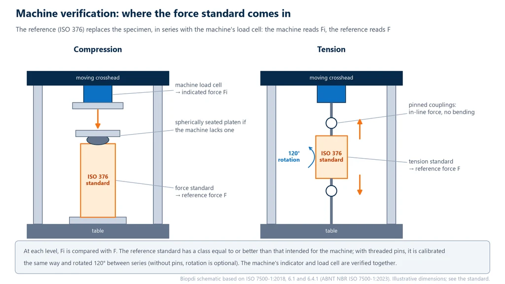
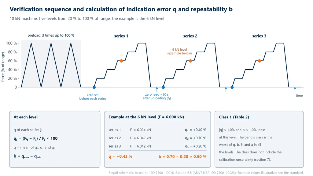
A force-proving instrument, usually a reference load cell or a proving ring, is mounted on the machine in place of the test specimen. The machine applies increasing forces, and at each level the force indicated by the machine, Fi, is compared with the reference force indicated by the proving instrument, F. The sequence is repeated in three series. The standard requires that:
- each series has at least five force levels, at approximately equal intervals, between 20% and 100% of the range;
- if the range is calibrated below 20%, supplementary points are added, at least five per decade below 20%;
- the force-proving instrument meets ISO 376 and has a class equal to or better than the class intended for the machine, with traceability to the International System of Units;
- the calibration is carried out between 10 °C and 35 °C, with the temperature of the proving instrument varying by no more than 2 °C during each series;
- the proving instrument, once mounted, is preloaded at least three times between zero and the maximum force (section 6.4.3);
- the indicator is zeroed before each series, and zero is read about 30 s after the force is removed (section 6.4.5).
The diagram shows the setup in both force directions. In compression, if the machine has no built-in spherical seat, a platen with a spherical seat is placed on top of the proving instrument; in tension, it is mounted so as to avoid bending. When the proving instrument is held by threaded studs, it must have been calibrated that way and is rotated 120° between one series and the next.
With the three series, the relative indication error of each series is calculated at each level, qj = (Fij − Fj) / Fj × 100, where Fij is the force indicated by the machine and Fj the reference force in series j. The relative indication error of the machine, q, is the mean of the three values. The repeatability, b, is the difference between the largest and smallest of them: b = qmax − qmin. This is the calculation of ISO 7500-1:2018 (section 6.5); the old Brazilian edition, NBR NM-ISO 7500-1:2004, used a different formula, based on the mean of the reference forces, and the two must not be mixed. The zero error, f0, and the relative resolution of the indicator, a, are also evaluated.
The diagram below shows the complete sequence, from the three preloads of the proving instrument to the three series, and this calculation at one force level. In the example, the machine meets class 1 at that level; the calibration uncertainty is not part of the class.
Classes 0.5, 1, 2 and 3
The class of the range is the worst of the classes reached by each parameter. The table summarizes the limits for each class, in percent (Table 2 of the standard):
| Class | Relative indication error (q) | Repeatability (b) | Relative resolution (a) | Zero error (f0) | Reversibility (v), when required |
|---|---|---|---|---|---|
| 0.5 | ±0.5% | 0.5% | 0.25% | ±0.05% | ±0.75% |
| 1 | ±1.0% | 1.0% | 0.5% | ±0.1% | ±1.5% |
| 2 | ±2.0% | 2.0% | 1.0% | ±0.2% | ±3.0% |
| 3 | ±3.0% | 3.0% | 1.5% | ±0.3% | ±4.5% |
Reversibility is only evaluated when required (section 6.4.8). The class also does not include the calibration uncertainty: the standard warns, in section 7, that belonging to a class does not guarantee that the error, added to the uncertainty, stays within the class value. Most testing standards require class 1 or better: this is the case of ISO 6892-1 (ABNT NBR ISO 6892-1 in Brazil), for tensile testing of metals (covered in detail in the guide to ASTM E8 and ISO 6892-1), and of ABNT NBR 5739, the Brazilian standard for concrete compression testing, which accepts class 2 only in job-site laboratories and ready-mix concrete plants.
The verified range and its lower limit
This is the point that most sets a testing machine load cell apart from a weighing load cell: the permissible error is a percentage of the measured force, not of full scale. A class 1 machine has a relative indication error of at most ±1% of the measured force throughout the verified range, whether the force is 9 kN or 300 N. An error given in % of full scale, by contrast, weighs more and more as the force decreases.
The range, however, has a floor, and it comes from the resolution of the indicator, r, the smallest force increment the machine displays. The relative resolution a = r / F × 100 increases as the force decreases, and the standard limits a to 0.5% in class 1. This is equivalent to requiring F ≥ 200 · r. ISO 7500-1 states the rule directly: the lower limit of the range cannot be less than r multiplied by 400 for class 0.5, 200 for class 1, 100 for class 2 and 67 for class 3.
The graph below shows these rules on a 10 kN machine with a resolution of 1 N. Each horizontal line is the permissible error of a class, constant in % of the indicated force from the lower limit (the dot, at 400, 200, 100 and 67 N) up to capacity; the blue band is the standard series from 20% to 100%. The orange curve shows, for comparison, what an error of 1% of full scale represents in % of the force read: 5% at 20% of capacity.
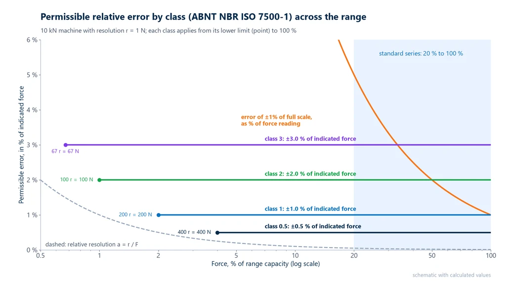
The limit set by resolution is the theoretical floor. The limit that applies to the laboratory is the one on the certificate: if the verification was done only from 20% to 100%, the declared class applies from 20% upward, and a force of 5% of capacity is outside the guarantee, even if the resolution would allow more. To use the machine below 20%, the verification must have included the supplementary points.
When to verify again
ABNT NBR ISO 7500-1 recommends verification at intervals of no more than 12 months, unless otherwise specified, and whenever the machine is dismantled to be moved or undergoes a major repair or adjustment. Some testing standards make the interval mandatory: NBR 5739 requires calibration to NBR ISO 7500-1 at least every 12 months. The complete process, from the certificate to the interval and the intermediate check, is covered in the guide to universal testing machine calibration. Replacing the load cell is a major repair to the force-measuring system, in which case the standard requires the machine to be verified again before results are issued again. The article on the universal testing machine also covers the verification interval under ASTM E4.
How to choose the load cell capacity for the test
You choose the load cell capacity for a test based on the test force, not on the catalog. The rule has two sides:
- At the top: the maximum expected force has to stay below the capacity, with a margin for materials that are stronger than nominal. Going past 100% takes the reading out of specification. Going past the safe load limit (150% on the Z6 load cell) can shift the zero permanently.
- At the bottom: the forces that matter for the result have to fall within the verified range. The maximum force alone is not enough. For the modulus of elasticity and the proportional limit, the relevant forces are at the start of the curve, well below fracture.
In practice, you look for the capacity that puts the fracture force between about 20% and 80% of the range. To estimate the force, multiply the specimen cross-sectional area by the expected strength of the material. When a laboratory tests everything from fine wire to thick bar, a single range cannot cover both ends. The solution is more than one machine or more than one verified range. The exercises below show the calculations.
How to test and calibrate a load cell
Testing and calibrating are different things, and people often confuse them. Testing means checking whether the load cell is sound, using simple instruments. Calibrating means relating the reading to forces of known, traceable value.
The multimeter test has two steps. First, with the load cell disconnected, measure the resistance between +EXC and −EXC and between +SIG and −SIG. The values should be close to the datasheet. A 350 Ω bridge is the most common case, and the input resistance is usually a little higher than the output resistance because of the compensation resistors. Also measure the insulation between the wires and the load cell body, which should be very high. Then, with the load cell powered, measure the signal with no load, which should be close to 0 mV, and with a known mass. A 2 mV/V load cell excited at 10 V should give about 10 mV at 50% of capacity. A zero that has shifted a lot points to a past overload or to moisture. Low insulation points to moisture ingress.
Calibration applies traceable forces at several points with increasing load. On a scale, this is done with standard masses. The force-proving instrument used to verify testing machines is itself calibrated to ISO 376:2011 (ABNT NBR ISO 376 in Brazil), which classifies it as class 00, 0.5, 1 or 2. On a testing machine, what counts is the calibration and verification of the whole system to ISO 7500-1 (ABNT NBR ISO 7500-1 in Brazil), described in the previous section. A laboratory with a traceable standard performs it.
Worked examples
These exercises apply the signal formulas, the class rule and the capacity selection.
Exercise 1: output signal at 60% of capacity
A 10 kN, 2 mV/V load cell excited at 10 V is loaded to 6 kN. What is the signal? What if the excitation is 5 V?
- Signal at capacity: VFS = 2 mV/V × 10 V = 20 mV.
- 6 kN is 60% of 10 kN: V = 20 mV × 0.60 = 12 mV.
- At 5 V: VFS = 10 mV and V = 10 × 0.60 = 6 mV. The same point gives half the signal, which is why the excitation has to be stable and known.
Exercise 2: permissible error of a class 1 machine in a 5 kN test
A test records a maximum force of 5 kN, within the verified range of a class 1 machine. What is the permissible error? And what if the same tolerance were 1% of the full scale of a 100 kN load cell?
- Class 1: the permitted error of indication is ±1.0% of the force, or 0.01 × 5,000 N = ±50 N. The calibration uncertainty stated on the certificate adds to this value. The standard warns that the class does not guarantee a result within ±1% once uncertainty is included.
- If it were 1% of the 100 kN full scale: ±1,000 N, or 20% of the measured force.
This is why ABNT NBR ISO 7500-1 states the error as a percentage of the measured force, limited to the verified range.
Exercise 3: lower limit of the range set by resolution
A machine has a resolution r = 1 N on one range. Down to what force can class 1 apply? And if r = 5 N?
- Class 1: Fmin ≥ 200 × 1 N = 200 N. At that point, a = 1 / 200 × 100 = 0.5%, exactly the limit.
- With r = 5 N: Fmin ≥ 200 × 5 N = 1,000 N.
The resolution of the electronics limits how far down the class can go. The certificate tells you how far down it was actually verified.
Exercise 4: choosing the capacity for a 1 kN wire and a 16 mm bar
A laboratory will run tensile tests on a wire that breaks at about 1 kN and on a 16 mm CA-50 rebar (the Brazilian 500 MPa reinforcing steel grade). The available machine has a 100 kN range with 10 N resolution. Is it suitable for both?
- Wire: 1 kN is 1% of 100 kN. The class 1 lower limit is 200 × 10 N = 2 kN, so the wire falls outside the range, even if the verification had supplementary points. The solution is a 2 to 5 kN range, which puts fracture between 20% and 50% of capacity.
- Bar, minimum force: nominal area π × 16² / 4 = 201.1 mm². Under ABNT NBR 7480:2024 (the Brazilian standard for steel reinforcing bars), CA-50 has fst ≥ 1.10 × 500 = 550 MPa, so Fmax ≥ 550 × 201.1 = 110,600 N, about 111 kN.
- Bar, reference force: real bars break above the minimum. At 600 MPa, F = 600 × 201.1 = 120,700 N, about 121 kN, already above 100 kN.
- On a 100 kN range, the bar exceeds the capacity. The reading goes out of specification and the load cell works close to its safe load limit. On a 200 kN range, 121 kN is 60% of capacity, with a margin for stronger bars.
Answer: the 100 kN machine is suitable for neither. The wire needs a range of a few kilonewtons and the 16 mm bar needs a 200 kN range. Selection by bar size is covered in detail in the NBR 7480 guide.
Exercise 5: a spliced cable on a 4-wire load cell
A 4-wire load cell had its cable extended by another 30 ft (about 9 m) of 28 AWG cable, with no recalibration. What is the estimated loss of sensitivity?
- Using Interface's estimate of 0.37% per 10 ft: 3 × 0.37% = 1.1%.
- The machine now reads about 1.1% low across the whole range, more than the ±1% of class 1. With a 6-wire cable and sense lines, the voltage drop in the cable would be compensated.
How to interpret it: questions that confuse professionals
The points below come up in purchase specifications, laboratory audits and discussions with suppliers. All of them come from mixing up class systems or reading only half of the certificate.
Is a C3 load cell the same as a class 1 machine?
No. There are three systems for three different things. Class C3 comes from OIML R 60, the regulation for weighing load cells: "C" is the accuracy class and "3" means 3,000 verification intervals. Classes 00, 0.5, 1 and 2 of ISO 376 apply to the force-proving instrument, which is used to calibrate machines. Classes 0.5, 1, 2 and 3 of ISO 7500-1 (ABNT NBR ISO 7500-1 in Brazil) apply to the force-measuring system of the whole testing machine, verified as assembled. A C3 load cell in a machine does not make the machine class 1, and a class 1 machine says nothing about OIML.
The OIML class belongs to legal metrology, which regulates selling by weight. In Brazil, this is regulated by Inmetro (the Brazilian national metrology institute). In the United States, the equivalent approval is NTEP. A load cell without OIML or NTEP approval is sold for general-purpose use. Its accuracy may be similar, but it cannot be used in a legal-for-trade scale.
Does "0.03% accuracy" on the load cell guarantee the machine class?
No. The datasheet figure applies to the load cell on a bench, as a percentage of full scale, under the manufacturer's conditions. The machine class also depends on mounting, alignment, cable, electronics and resolution, and it only exists after verification. A very good load cell is a necessary condition, but not a sufficient one.
Is a class 1 machine class 1 at any force?
No. It is class 1 within the verified range of each force range, as stated on the certificate. Below the lower limit, the machine may still display a number, but with no guarantee of accuracy. Checking the lower limit on the certificate is part of preparing any low-force test.
Why does the software show a non-zero force with no load?
The weight of the grip and accessories hanging from the load cell, thermal drift and small bridge imbalances all produce a signal. The normal procedure is to zero (tare) the force with the grip mounted and the specimen still free at one end. A zero that does not settle, or that changes a lot from one day to the next, is a sign of a problem with the load cell or the cable.
Are calibrating the load cell and verifying the machine the same thing?
No. The load cell may have a factory calibration certificate, done on a bench. The machine needs verification to ABNT NBR ISO 7500-1, done with the load cell installed and with a traceable standard. Machine verification is what test standards require and what the auditor checks.
Common load cell mistakes
The most frequent mistakes are not in the load cell design but in how it is used. Each one has a measurable consequence:
- Side load, bending moment or torsion. The load cell is calibrated for axial force. A misaligned grip or a crooked specimen introduces parasitic forces that enter the reading or damage the load cell.
- Overload. Above the safe load limit, the zero can shift permanently. The shock when brittle specimens fracture and a weight dropped on the load cell also count as overload.
- Cutting or splicing the cable of a 4-wire load cell. This changes the sensitivity, as in exercise 5. For long cables, use 6 wires with sense lines.
- Expired calibration, or a load cell replaced without new verification. The stated class only applies to the verified assembly.
- Testing outside the verified range. A small force on a large load cell falls below the lower limit, like the wire in exercise 4.
- Confusing % of full scale with % of indicated force. The datasheet uses the first; ABNT NBR ISO 7500-1 uses the second.
- Buying to the wrong class. Requiring "C3" on a testing machine, or "class 1" on a scale, mixes systems that do not convert.
- Ignoring temperature. A thermal gradient across the load cell, from sunlight, air conditioning or a nearby oven, causes zero drift.
- Neglecting creep in long tests. In creep and relaxation tests, the load cell drift adds to the phenomenon being measured.
- Unshielded or poorly grounded cable. With a millivolt signal, noise from motors and drives shows up on the curve.
The load cell in the Biopdi universal testing machine
Biopdi's M2 line of universal testing machines ranges from 200 N to 1,000 kN. On these machines, as on any machine, the ABNT NBR ISO 7500-1:2023 class does not belong to the load cell. It belongs to the machine's force-measuring system, verified with the load cell installed, range by range. The load cell sits in series with the grip or platen, and the BioLab software receives the force together with the crosshead displacement and the strain from the extensometers. The panel below shows the machine, the role of each part in force measurement and the fixtures that transmit the force from the specimen to the load cell.
The universal testing machine and force measurement
The M2 line has single-column models from 200 N to 10 kN and dual-column models from 5 kN to 1,000 kN. In force measurement, each part of the machine has a role:

- Moving crosshead applies the force in tension or compression
- Load cell measures the force; the NBR ISO 7500-1 class belongs to the measuring system verified with it installed
- Grips and platens transmit the force from the specimen to the load cell
- Extensometer measures strain, from 25 to 250 mm
- Data acquisition electronics excite the bridge and read the signal
- BioLab software force-displacement curve and report
Fixtures that carry the force to the load cell
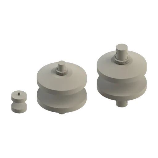
The fixtures below mount on the same machine, depending on the test and the force range:
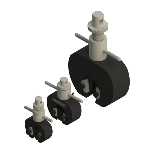
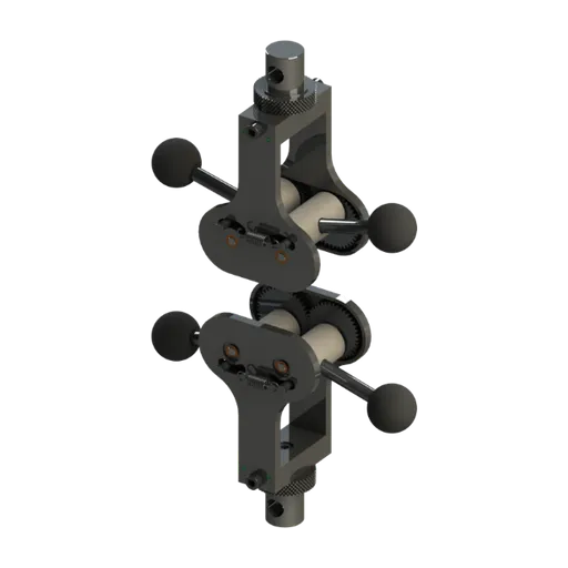
The machine capacity follows the test force, using the rule from the selection section. For wire, film and tape, with forces from a few newtons to 1 kN, the model is the portable machine from 200 N to 1 kN. For plastics, mortar and thicker wire, use the single-column machine from 2 to 10 kN. For rebar up to 16 mm, use the dual-column machine from 100 to 200 kN, and for larger bar sizes, the models from 300 kN up. The full line is on the universal testing machine page, and the BioLab software records the curve, calculates the properties and exports the report. The load cell configuration follows the machine configuration and is defined in each laboratory's project. To size yours, request a quote.
Standards cited
The table lists the standards cited. We checked the current ISO and ASTM editions on October 1, 2026, in the ISO catalog (both reviewed and confirmed in 2026) and in the ASTM store (both active). We checked the ABNT editions on September 30, 2026, in the ABNT record (Target):
| Standard | Subject | Edition |
|---|---|---|
| ABNT NBR ISO 7500-1 | calibration and verification of the force-measuring system of tension/compression testing machines (Brazilian adoption of ISO 7500-1) | 2023, with 2023 corrigenda |
| ISO 7500-1 | international basis of the Brazilian standard | 2018, confirmed in 2026 |
| ISO 376 | calibration and classification of force-proving instruments | 2011, confirmed in 2026 |
| ASTM E4 | force verification of testing machines (USA) | E4-24 |
| ASTM E74 | calibration of force-measuring instruments (USA) | E74-18(2026) |
| OIML R 60 | metrological regulation for weighing load cells | R 60-1:2021 |
| ABNT NBR 7480 | steel for reinforced concrete (Brazil) | 2024 |
| ABNT NBR 5739 | compression testing of cylindrical concrete specimens (Brazil) | 2018 |
Other tests and technical references
Tests performed on the Biopdi universal testing machine



















Related technical references
ISO 898-1: bolt property classes (8.8, 10.9, 12.9), proof load and testing
ISO 898-1:2013 defines the property classes of carbon steel and alloy steel bolts, from 4.6 to 12.9, and the tests that verify them. See what each number means, the summary table, the stress area of an M12 (84.3 mm²), the breaking and proof loads in kN, the tests and how to choose the testing machine.
Mechanical testing: what it is, types, what each test measures and standards
Mechanical tests apply a controlled load to a test specimen and measure the material's response. See the types (destructive, non-destructive, static and dynamic), what each test measures, the standards and the machine for each one.
Materials testing: what it is, types, destructive and non-destructive testing, standards and how to choose
Materials testing is the standardized procedure that measures the mechanical, physical, chemical or microstructural properties of a representative sample, or that inspects a part without damaging it. See the five families of tests, the difference between destructive and non-destructive testing, the test specimen, accreditation, the standards and how to choose the right test.
Frequently asked questions
What is a load cell?
It is an electromechanical sensor that converts force or weight into an electrical signal. The force deforms a metal body, strain gauges bonded to it change resistance, and a Wheatstone bridge delivers a voltage of a few millivolts per volt of excitation, proportional to the force. The typical value is 2 mV/V at rated capacity.
What does a load cell do?
It measures force or weight and sends a proportional electrical signal to an indicator, a PLC or software. Load cells are used in scales, silos, presses and test benches; in a universal testing machine, the load cell measures the force at every point of the curve.
How does a load cell work?
The force deforms the elastic element by about 1,000 µm/m at rated capacity. The strain gauges change resistance in proportion ΔR/R = k·ε, with k close to 2, and the full bridge, with two gauges in tension and two in compression, converts this into about 2 mV per volt of excitation.
What are the types of load cells?
The main types are the S-type (or Z-type), column, pancake, single point, bending beam or shear beam, load pin and button load cells. The choice depends on the direction of the force, the capacity and the available space: S-type and pancake for tension and compression, column for high compression loads, single point and beam for weighing.
What does mV/V mean on a load cell?
It is the output at rated capacity per volt of excitation. A 2 mV/V load cell excited at 10 V delivers 20 mV at rated capacity and 12 mV at 60% of it. At 5 V, it delivers half that.
What is a 500 kg or 100 kg load cell?
It is a load cell with a rated capacity of 500 kgf, about 4.9 kN (500 × 9.80665 N), or 100 kgf, about 0.98 kN. The number is the maximum specified force, and normal use stays below it. Datasheets such as that of the HBM Z6 allow up to 150% without damage and state breaking load near 300%, but above 100% the reading falls outside the specification.
How much does a load cell cost?
Prices range from inexpensive models for hobby use and simple scales to certified reference transducers that cost many times more. The price rises with accuracy, capacity, material and degree of protection (stainless steel and IP68), type, and calibration traceability.
How do you test a load cell with a multimeter?
With the power off, measure the resistance between the excitation wires and between the signal wires (a typical bridge is 350 Ω), and the insulation to the body. With the power on, check the signal with no load, close to 0 mV, and with a known mass: at 2 mV/V and 10 V, at 50% of capacity, expect about 10 mV.
How do you calibrate a load cell?
Apply known forces, using standard masses or a traceable force standard, at several increasing points, and adjust the indicator. On a testing machine, calibration and verification follow ISO 7500-1 (ABNT NBR ISO 7500-1 in Brazil), with a force standard calibrated per ISO 376 of a class equal to or better than the one intended for the machine.
How do you wire a load cell?
Connect the excitation wires (+EXC and −EXC) to the excitation supply of the indicator or signal conditioner and the signal wires (+SIG and −SIG) to its input, following the load cell datasheet or certificate. A common color code, Interface's, is red +EXC, black −EXC, white +SIG and green −SIG, but colors vary by manufacturer; the cable shield goes to ground on the instrument side.
What is a 4-wire load cell and how does it differ from a 6-wire one?
A 4-wire load cell has only excitation and signal wires. A 6-wire load cell adds sense wires, which measure the excitation at the load cell itself and compensate for the voltage drop in the cable and its variation with temperature. For 4-wire cells, Interface estimates a loss of about 0.37% per 10 feet of 28 AWG cable; that is why the cable of a 4-wire load cell must not be cut or spliced.
What is an S-type load cell?
It is a load cell with an S-shaped body, mounted through threaded holes at the ends, that measures in-line tension and compression. It is used in hanging scales, test benches and low-capacity testing machines. The HBM S9M, for example, ranges from 500 N to 50 kN.
What is a tension load cell?
It is a load cell that measures tensile load, the force that tends to stretch a part, such as the load on a cable, a tie rod or a test specimen under tension. The usual geometries are S-type or Z-type, pancake and tension column; in a universal testing machine, the same load cell measures tension and compression, with a signal of opposite polarity.
What is a class 1 testing machine?
Under ISO 7500-1 (ABNT NBR ISO 7500-1 in Brazil), it is a machine whose force-measuring system has a relative error of indication of up to ±1% of the force and a repeatability of up to 1%, over the entire verified range. In a 5 kN test, this means ±50 N of indication error; the calibration uncertainty is not included in the class.
How do you choose the load cell capacity for a test?
Estimate the maximum force of the test and choose the capacity that places it between about 20% and 80% of the range, with a margin against overload. A very small force on a large load cell falls below the lower limit of the verified range, which for class 1 is at least 200 times the resolution.