
The CBR test (California Bearing Ratio), known in Brazil as the ensaio do Índice de Suporte Califórnia (ISC), measures how well a compacted soil resists penetration by a standard piston. The result is given as a percentage of the resistance of a standard crushed stone. The piston is 49.6 mm in diameter (19.32 cm²). It penetrates at 1.27 mm/min into a test specimen that has been soaked in water for 4 days. The pressures read at 2.54 mm and 5.08 mm are divided by the standard crushed-stone pressure at those penetrations: CBR (%) = corrected pressure / standard pressure × 100, with 6.9 MPa at 2.54 mm and 10.35 MPa at 5.08 mm. A CBR of 15% means the soil resists 15% of what the reference crushed stone resists.
In Brazil the test follows ABNT NBR 9895:2025 (the Brazilian standard for the CBR test) and DNIT 172/2016-ME (the test method of DNIT, Brazil's federal transport infrastructure agency). The result is used to accept subgrade, subgrade reinforcement, subbase and base materials, and to design flexible pavements with the method of the DNER (Brazil's former National Highway Department). Below we cover what the test measures, the standards, the three phases step by step, the calculation with curve correction, a worked example, the values required for each layer, how the result is used in pavement design, and the mistakes that distort the result most.
What the CBR test is and what it is used for
The CBR test is an empirical soil laboratory test that compares the behavior of a soil with that of a reference material. CBR stands for California Bearing Ratio; ISC is the Portuguese name. Both terms refer to the same test and the same number.
What is a CBR test?
It is a penetration test. A cylindrical piston is pushed at constant speed into a compacted soil test specimen in a mold, and the press records the force at each penetration. The force divided by the piston area gives the pressure. In essence, it is a localized compression test under displacement control. The pressure the same piston needs to penetrate a reference crushed stone is called the standard pressure, and by definition it corresponds to a CBR of 100%. The CBR of the soil is the ratio between the two pressures, as a percentage.
Because it is a comparison with crushed stone, the CBR is not a physical property of the soil like the modulus of elasticity. It depends on the molding moisture content, the density achieved and the compaction energy, which is why the standard fixes all these conditions. Change the conditions and the number changes.
What is the CBR test used for?
The CBR test measures the bearing capacity of a soil compared with a standard crushed stone, and this value is essential in pavement engineering, especially for roads and highways. In practice it has two uses. The first is material acceptance: DNIT specifications set a minimum CBR and a maximum swell for each pavement layer. The second is design: in the DNER method, the pavement thickness over the subgrade comes from the subgrade CBR and the traffic. Beyond highways, the same index is used in the design of airport pavements, yards and industrial slabs on grade, urban streets and housing developments, and in the control of borrow pits and embankments.
What materials does the CBR test evaluate?
The CBR test evaluates compacted soils and granular materials: subgrade clays and silts, sands, gravels, soil and crushed stone mixtures, and subgrade reinforcement, subbase and base materials. The fraction retained on the 19 mm sieve is discarded or replaced before molding, depending on the amount, as shown in the sample preparation. Cement- or lime-stabilized materials have their own specifications and, in mechanistic design, are characterized by resilient modulus and fatigue, not only by the CBR.
Compaction and CBR: what is the difference?
They are two measurements made on the same test specimens. The CBR specimens are compacted in the test's own mold, with the energies of NBR 7182:2025 (see the guide to soil compaction and the Proctor test), which gives the curve of moisture content versus dry density, with the optimum moisture content and the maximum dry density. The same specimens then go through the 96-hour soaking, which measures swell, and then the penetration, which gives the CBR. The compaction, CBR and swell curves are plotted on the same sheet, with the same moisture scale. DNIT 172/2016-ME reads the soil CBR at the optimum moisture content; NBR 9895:2025 requires reading it on the curve according to the project criterion.
Origin of the test
The method was created in the late 1920s by O. J. Porter, at the California Division of Highways, to evaluate highway materials. In 1942 the U.S. Army Corps of Engineers adapted it for military airfield runways, and that version is the one that spread. In Brazil, the flexible pavement design method of the former DNER, by Murillo Lopes de Souza, uses the CBR of the subgrade and of the layers, which explains why the test is found in practically every highway soil laboratory. The test is part of the daily routine of infrastructure civil engineering.
Main standards for performing the CBR test (California Bearing Ratio)
In Brazil there are two test method standards for the CBR test, one from ABNT and one from DNIT, and they agree on the key points: mold, piston, 96-hour soaking, 1.27 mm/min rate, standard pressures and the rule of adopting the greater of the two CBR values. Sample preparation and compaction have their own standards. The editions below were checked on October 1, 2026 in the ABNT catalog (Target), on the DNIT portal (gov.br) and in the ASTM store, and the text of NBR 9895:2025 was checked on October 5, 2026.
| Standard | Title | What it defines in the test |
|---|---|---|
| ABNT NBR 9895:2025 | Soil: California Bearing Ratio (CBR): Test method | Laboratory method for CBR and swell, with disturbed, non-reused samples of material passing the 19 mm sieve, at least five test specimens |
| DNIT 172/2016-ME | Soils: Determination of the California Bearing Ratio using non-reused samples | Apparatus, blows per layer, soaking, penetration, Table 3 of standard pressures and curve correction; cancels DNER-ME 049/94 |
| DNER-ME 162/94 | Soils: compaction test using reused samples | Compaction with reused sample |
| DNIT 164/2013-ME | Soils: compaction using non-reused samples | Compaction required in the layer specifications |
| ABNT NBR 6457:2024 | Soils: Preparation of samples for compaction and characterization tests and determination of moisture content | Drying, breaking up of clods and moisture content of the sample |
| ABNT NBR 7182:2025 | Soils: Compaction test | Relationship between moisture content and dry density (Proctor) |
| DNIT 459/2025-ME | Soils: Particle size analysis | Soil particle size distribution required in the layer specifications; cancels DNER-ME 051/94 and 080/94 |
| DNIT 254/2023-ME | Soils: Compaction in miniature equipment: Mini-CBR and swell | Miniature version of the test, on a 50 mm test specimen, for tropical soils; cancels DNER-ME 254/97 |
| ASTM D1883-21 | California Bearing Ratio (CBR) of Laboratory-Compacted Soils | International reference; same penetrations, with standard pressures of 1,000 and 1,500 psi |
One point that causes confusion: NBR 6457 is not the compaction test. It covers sample preparation (preliminary drying, breaking up of clods, quartering and determination of moisture content). The standard, intermediate and modified Proctor compaction energies belong to NBR 7182. NBR 9895 had editions in 1987, 2016 (with a corrected version in 2017, confirmed in 2020) and 2025 (3rd edition, July 2025, which cancels and replaces the 2016 edition); anyone still citing the 2016 edition in a new test report should update the reference. DNIT 172/2016-ME remains in force (checked in the DNIT standards collection on October 1, 2026). Outside Brazil, besides ASTM D1883, there is AASHTO T 193, the AASHTO method for the same test.
Particle size analysis, which the specifications require together with the CBR, has also changed standard at DNIT. For soils, DNIT 459/2025-ME applies; it was approved in July 2025, corrected by Errata 1 in April 2026, and canceled DNER-ME 051/94 and DNER-ME 080/94. The ABNT equivalent is NBR 7181:2025. For aggregates, DNIT 412/2025-ME applies, which replaced DNER-ME 083/98. The 2010 subbase and base specifications still cite the old standards, and a new test report should cite the current ones.
Mini-CBR
The Mini-CBR is the miniature version of the test, standardized by DNIT 254/2023-ME. It uses 50 mm diameter test specimens, compacted in miniature equipment according to DNIT 228/2023-ME, and is used for a quick evaluation of the bearing capacity of fine tropical soils, within the MCT (Miniature, Compacted, Tropical) methodology. The press is similar to the CBR press, with a 4,905 N (1,103 lbf) load-measuring assembly. The Mini-CBR does not replace the DNIT 172/2016-ME CBR in the layer specifications.
How to perform the CBR test (California Bearing Ratio)?
The test has 3 main phases, in this order: compaction of the specimens, swell during soaking, and penetration resistance. Before them come the equipment and the sample preparation, which determine whether the result can be compared with the standard pressure. The procedure described here follows DNIT 172/2016-ME (the CBR test method of DNIT, Brazil's federal highway agency), which is the publicly available text of the method. NBR 9895:2025 (the Brazilian standard for the CBR test) follows the same sequence, with minor differences that are pointed out at each step: 14 penetration readings instead of 9, a surcharge of 4,540 ± 20 g, a rigid base heavier than 100 kg, a specific rule for the fraction above 19 mm, and the final CBR read according to the project criterion.
Test equipment
The CBR mold is larger than the standard Proctor mold, because the specimen needs a diameter large enough for the piston to penetrate far from the walls. The spacer disc is placed at the bottom during compaction and then removed, leaving above the soil the space that receives the perforated plate and the surcharge weights. The table summarizes the dimensions of DNIT 172/2016-ME:
| Item | Value | Function |
|---|---|---|
| Cylindrical mold | Inside Ø 152.4 mm, height 177.8 mm, with extension collar | Confines the specimen |
| Spacer disc | Ø 150 mm (150.8 mm in NBR 9895), height 63.5 mm | False bottom during compaction |
| Rammer | 4.536 kg, Ø 50.8 mm, 457.2 mm drop | Applies the compaction energy |
| Surcharge | 2.27 kg annular weights, total above 4.536 kg (4.54 kg ± 20 g per NBR 9895) | Simulates the weight of the overlying layers |
| Swell dial gauge (extensometer) | 0.01 mm graduations, minimum travel of 10 mm | Reads the swell on the tripod |
| Penetration piston | Ø 49.6 mm (area of 1,932 mm²) | Penetrates the specimen |
| Proving ring assembly | 50 kN, sensitive to 25 N, or load cell | Measures the force |
| Penetration dial gauge (extensometer) | 0.01 mm graduations, travel greater than 12.70 mm | Measures the piston penetration |
DNIT 172/2016-ME and NBR 9895:2025 allow the proving ring to be replaced by a load cell system with a readout unit, which gives the load directly, without the ring's calibration chart. The two standard pressures, multiplied by the piston area, correspond to about 13.3 kN at 2.54 mm and 20.0 kN at 5.08 mm: this is the force required by a crushed stone with a CBR of 100%, and it fits comfortably within the 50 kN assembly of the standard.
Sample preparation
Under DNIT 172/2016-ME, the sample is air-dried, broken up, homogenized and reduced by quartering to 6,000 g, for silty or clayey soils, or 7,000 g, for sandy or gravelly soils, per specimen; NBR 9895:2025 recommends 50 kg of sample in total, prepared according to NBR 6457 (the Brazilian standard for soil sample preparation). It is passed through the 19 mm sieve, and the retained material is replaced by an equal mass of material passing the 19 mm sieve and retained on the 4.8 mm sieve, taken from another portion of the same sample. Under NBR 9895:2025, the replacement applies only when the material retained on the 19 mm sieve exceeds 10%; below that it is discarded, and above 30% the method does not apply. The operation is repeated for each specimen, at least five. The sample is not reused: each test specimen uses soil that has never been compacted before, because reuse breaks grains and changes the result.
Specimen compaction
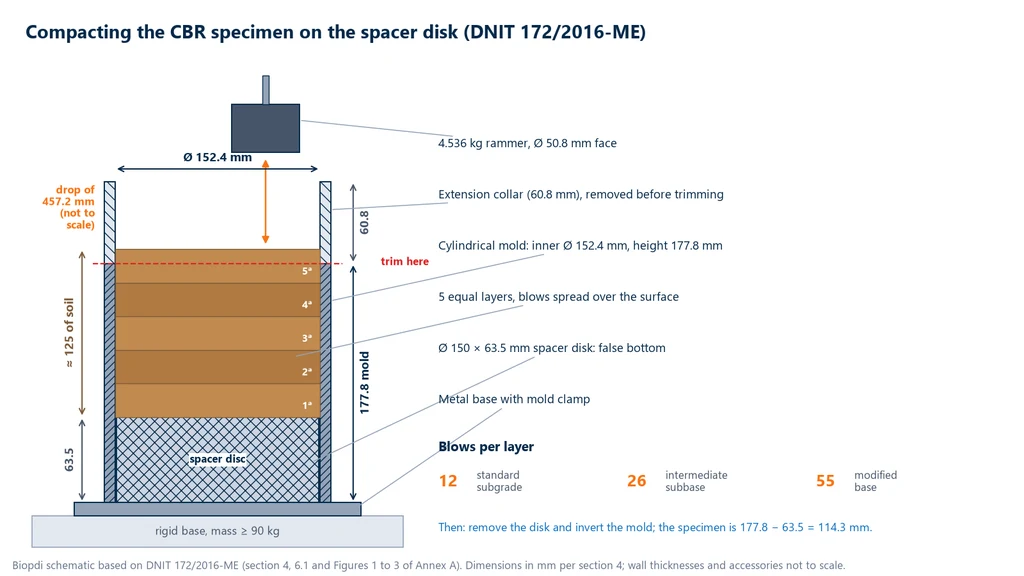
The specimens, at least 5, are compacted in the mold, on the spacer disc, in 5 equal layers, up to about 12.5 cm of soil. The mold rests on a rigid base of at least 90 kg under DNIT 172/2016-ME (over 100 kg, preferably concrete, under NBR 9895:2025), so that the energy of the blows is not lost. Each specimen is given a higher moisture content than the previous one, so that together they trace the compaction curve. NBR 9895:2025 calls for starting about 5 percentage points below the presumed optimum moisture content, lightly scarifying each layer before placing the next, and leaving at most 10 mm of excess above the mold.
The water for each specimen is calculated from the current moisture content of the sample. The calculation below is from the UNILA teaching manual (2022) (UNILA is a Brazilian federal university), and the standards do not spell it out: the dry mass is Ps = Ph / (1 + h/100), where Ph is the wet mass and h is the current moisture content in %; the mass at the target moisture content w is Ps × (1 + w/100); and the difference between the two, in grams, is the volume of water to add, in milliliters. For 6,000 g of soil at 8% moisture and a target of 14%, Ps = 6,000 / 1.08 = 5,556 g, the mass at the target is 5,556 × 1.14 = 6,333 g, and 333 mL of water are added.
The number of blows per layer defines the energy and depends on the pavement layer the material is intended for:
| Energy | Blows per layer | Layers | Use in DNIT 172/2016-ME |
|---|---|---|---|
| Standard | 12 | 5 | Subgrade |
| Intermediate | 26 | 5 | Subbase |
| Modified | 55 | 5 | Base |
The diagram below shows a cross-section of the mold during compaction, with the dimensions of DNIT 172/2016-ME. Note the 63.5 mm spacer disc at the bottom, the 60.8 mm extension collar receiving the excess of the 5th layer, the dashed line where the soil is trimmed at the top of the mold, and the assembly resting on a rigid base of at least 90 kg, as DNIT 172/2016-ME requires.
Standard Proctor is the common name for the standard compaction energy, inherited from the compaction test published by R. R. Proctor in 1933; the intermediate and modified energies apply more blows with the same rammer. In the large CBR mold, all three use the 4.536 kg rammer with a 457.2 mm drop, in 5 layers, and differ only in the number of blows in the table above. In the small cylinder of NBR 7182:2025 (the Brazilian soil compaction standard), the blows and the rammer are different, so the energy should always be stated together with the mold.
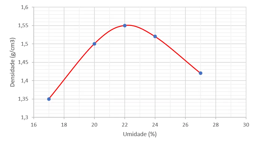
The selected energy must match the compaction expected in the field; the project may propose a different energy, subject to approval by IPR/DNIT (the road research institute of DNIT). After compaction, the extension collar is removed, the soil is trimmed flush with the top of the mold, and the assembly is weighed to the nearest 5 g. A sample of about 100 g of the excess goes into the oven at 105 °C to 110 °C to give the molding moisture content. These two details come from DNIT 172/2016-ME; under NBR 9895:2025, weighing has a resolution of 1 g and the moisture content is taken from a portion left in the tray, right after compaction of the 2nd layer. From the mass and the moisture content, the dry density is calculated, and the points of the five specimens form the compaction curve: the peak gives the maximum dry density and the optimum moisture content. The graph below shows a typical curve, with a peak of 1.55 g/cm³ at 22% moisture content:
Swell
Once compaction is finished, the spacer disc is removed and the mold is inverted and clamped to the perforated base plate, so that the 63.5 mm space left by the disc sits above the soil. This space receives the perforated swell plate with its stem and the annular surcharge, with a mass above 4.536 kg under DNIT 172/2016-ME; NBR 9895:2025 specifies two annular weights with a total mass of 4,540 ± 20 g. A dial gauge mounted on a tripod, resting on the rim of the mold, touches the stem. The assembly is soaked in water for 96 hours (4 days; at least 96 hours, under NBR 9895), with a reading every 24 hours. The diagram below shows a cross-section of the mold in this phase, with the dimensions used in the calculation:
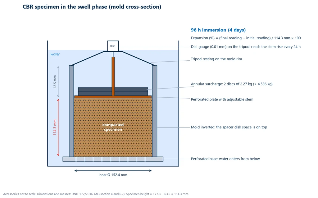
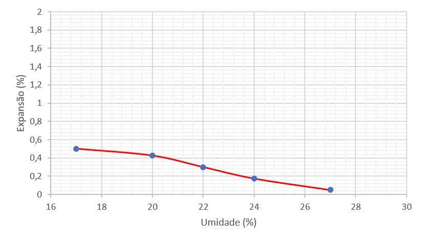
Swell is the change in specimen height as a percentage of the initial height, which is the mold height minus the spacer disc height: 177.8 − 63.5 = 114.3 mm. Soaking puts the soil in the worst moisture condition it is expected to face in service, and the surcharge represents the weight of the pavement above. Soils with expansive clay minerals swell considerably in this phase, and high swell rejects the material even if its CBR is good. At the end of the 4 days, the mold is removed from the water and allowed to drain for 15 minutes. Plotted against molding moisture content, swell usually decreases as moisture content increases, as the graph shows:
Penetration resistance
After draining, the specimen goes to the press with the same surcharge weights used for swell. The piston is seated on the soil with a load of about 45 N, the two gauges (load and penetration) are zeroed, and the press advances at 1.27 mm/min. Load readings are taken at the penetrations of Table 3 of DNIT 172/2016-ME: 0.63; 1.27; 1.90; 2.54; 3.81; 5.08; 7.62; 10.16 and 12.70 mm. At the rate set by the standard, the 12.70 mm penetration is reached in 10 minutes. NBR 9895:2025 adds five readings, at 3.17; 4.44; 6.35; 8.89 and 11.43 mm (2.5; 3.5; 5; 7 and 9 min), for a total of 14. Dividing each force by the piston area gives the pressure × penetration curve of each specimen, which is the raw material for the calculation in the next section.
In the manual press described by DNIT 172/2016-ME, the 49.6 mm piston passes through the 54 mm hole of the annular surcharge, the proving ring suspended from the crosshead measures the force, and the penetration dial gauge, attached to the piston, rests its stem on the rim of the mold. The diagram below shows this setup and, at the bottom, the nine penetration readings with the times corresponding to 1.27 mm/min; those at 2.54 and 5.08 mm, in orange, are the ones used for the CBR.
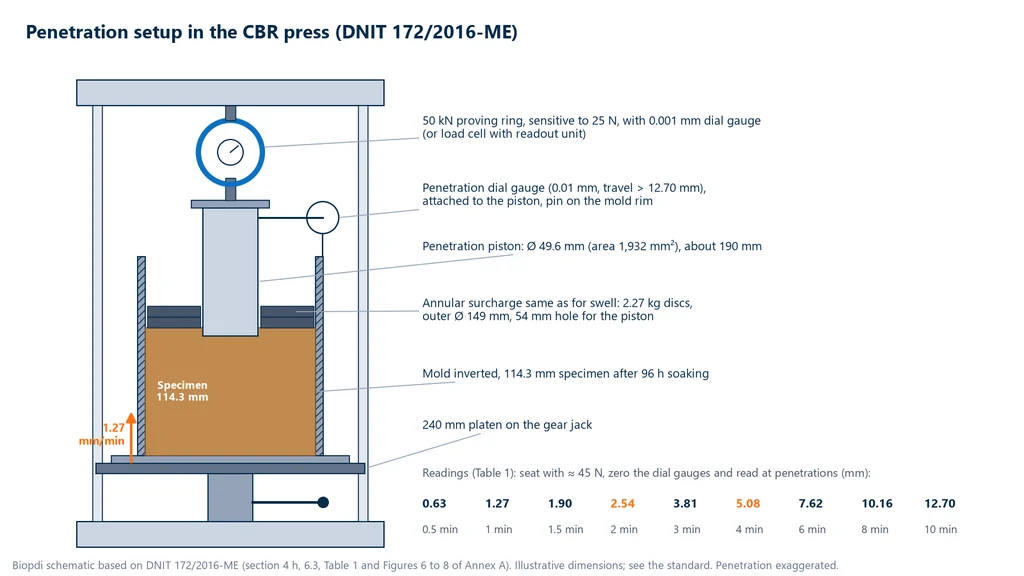
In the automatic press, the load cell and the displacement transducer record the force and penetration pairs continuously, and the software plots the curve in real time. In the manual press, the operator turns the crank trying to hold 1.27 mm/min and writes down the ring readings at the times in the table, which makes both the rate and the reading dependent on the operator. The simulation below walks through the three phases, compaction, swell and penetration, and shows the CBR read at 2.54 and 5.08 mm for different soils and energies.
Interactive simulation
Try the test in your browser and watch the results being calculated.
How to calculate CBR: formula, standard pressures and curve correction
To calculate the CBR, divide the force read on the piston by the piston area, 19.32 cm² (1,932 mm², 49.6 mm diameter), then divide that pressure by the standard pressure of crushed stone: 6.9 MPa at 2.54 mm and 10.35 MPa at 5.08 mm. Multiply by 100. Under DNIT 172/2016-ME (the CBR test method of DNIT, Brazil's federal highway agency) and ABNT NBR 9895:2025 (the Brazilian standard for the CBR test), the higher of the two values is reported.
The calculation turns the pressure vs. penetration curve of each test specimen into two numbers, the CBR at 2.54 mm and the CBR at 5.08 mm, and selects one of them. Before that, the curve may need to be corrected. Afterwards, the CBR of each specimen is plotted against moisture content, and the CBR of the soil is read from that curve: at the optimum moisture content under DNIT 172/2016-ME, and according to the project criterion under NBR 9895:2025.
CBR formula
The pressure on the piston is the force divided by the area: p = F / A, with A = π × 49.6² / 4 = 1,932 mm². With F in newtons, p is in MPa. The index is:
CBR (%) = calculated or corrected pressure / standard pressure × 100
The pressure is calculated at 2.54 mm and at 5.08 mm, and each is divided by its own standard pressure. DNIT 172/2016-ME and NBR 9895:2025 (note to 5.5.3.3) require the higher of the two values to be reported. The dry density of each specimen comes from ρh = Mh / V and ρs = ρh / (1 + w/100), where V = volume of soil compacted in the mold and w = molding moisture content in %. Swell is (final reading − initial reading) / initial height × 100.
Standard pressures for crushed stone
The standard pressures are the pressures that a reference crushed stone, with a CBR of 100%, offers to the piston at each penetration. DNIT 172/2016-ME tabulates them in kgf/cm²; the exact conversion uses 1 kgf/cm² = 0.0980665 MPa. The table shows the values used in the calculation:
| Penetration | kgf/cm² (DNIT 172) | MPa | Equivalent force on the piston |
|---|---|---|---|
| 2.54 mm (0.1 in) | 70.31 | 6.9 | about 13.3 kN |
| 5.08 mm (0.2 in) | 105.46 | 10.35 | about 20.0 kN |
| 7.62 mm (0.3 in) | 131.58 | 12.9 | about 24.9 kN |
| 10.16 mm (0.4 in) | 161.71 | 15.9 | about 30.6 kN |
| 12.70 mm (0.5 in) | 182.80 | 17.9 | about 34.6 kN |
Only the first two rows enter the CBR. DNIT 172/2016-ME tabulates the others without using them in the calculation; NBR 9895:2025 gives only the first two, already in MPa (6.90 and 10.35). The check is straightforward: 70.31 × 0.0980665 = 6.895 MPa and 105.46 × 0.0980665 = 10.342 MPa, which in practice are rounded to 6.9 and 10.35 MPa; the rounding changes the CBR by less than 0.1%. The DNIT 172/2016-ME note that approximates 1 kgf/cm² as 0.1 MPa only shifts the CBR, by about 2%, if it is used for one of the pressures and not the other. ASTM D1883 expresses the same pressures as 1,000 and 1,500 psi and rounds the second to 10.3 MPa; the interactive simulation above uses that rounding, which changes the CBR at 5.08 mm by less than 0.5%.
Penetration reading sheet
The sheet below follows the times and penetrations of Table 3 of NBR 9895:2025, with 14 readings; the 9 marked "yes" are those of DNIT 172/2016-ME. It is filled in with the test specimen from the worked example further below (1.30 kN at 2.54 mm and 2.05 kN at 5.08 mm). The other forces are illustrative values from the same curve, with no initial inflection, and the pressure is the force divided by 1,932 mm².
| Time (min) | Penetration (mm) | Reading in DNIT 172 | Force (N) | Pressure (MPa) | Standard pressure (MPa) | CBR (%) |
|---|---|---|---|---|---|---|
| 0.5 | 0.63 | yes | 400 | 0.207 | ||
| 1.0 | 1.27 | yes | 750 | 0.388 | ||
| 1.5 | 1.90 | yes | 1,050 | 0.543 | ||
| 2.0 | 2.54 | yes | 1,300 | 0.673 | 6.9 | 9.8 |
| 2.5 | 3.17 | no | 1,520 | 0.787 | ||
| 3.0 | 3.81 | yes | 1,720 | 0.890 | ||
| 3.5 | 4.44 | no | 1,890 | 0.978 | ||
| 4.0 | 5.08 | yes | 2,050 | 1.061 | 10.35 | 10.3 |
| 5.0 | 6.35 | no | 2,320 | 1.201 | ||
| 6.0 | 7.62 | yes | 2,550 | 1.320 | ||
| 7.0 | 8.89 | no | 2,740 | 1.418 | ||
| 8.0 | 10.16 | yes | 2,900 | 1.501 | ||
| 9.0 | 11.43 | no | 3,040 | 1.573 | ||
| 10.0 | 12.70 | yes | 3,160 | 1.635 |
On a manual press, the force column is the proving ring reading converted with its calibration curve; with a load cell, it is read directly in newtons. The intermediate readings do not enter the CBR, but they draw the curve and show whether there is an inflection point to correct.
Curve correction at the inflection point
An ideal pressure vs. penetration curve starts straight or concave downward. When the top of the test specimen is irregular, a cause pointed out by DNIT 172/2016-ME, or the piston has not seated properly, the start of the curve is concave upward: the piston sinks without real resistance in the first tenths of a millimeter, and the pressures read at 2.54 and 5.08 mm are lower than what the soil actually offers. The correction in DNIT 172/2016-ME and NBR 9895 shifts the origin of the curve:
- locate the inflection point, where the curve changes from concave to convex;
- draw the tangent to the curve at that point until it intersects the penetration axis;
- measure the distance c between that point and the origin;
- add c to the 2.54 and 5.08 mm penetrations and read the corrected pressures at the new abscissas.
The graph below applies the procedure to an illustrative curve with c = 0.50 mm: the pressures that would be read at 2.54 and 5.08 mm are now read at 3.04 and 5.58 mm, and the reported CBR rises from 18.4% to 20.3%:
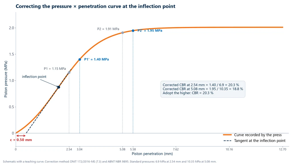
Without correction, the pressures read would be 1.15 MPa (CBR 16.7%) and 1.91 MPa (CBR 18.4%), and the report would give 18.4%. With correction, 1.40 / 6.9 = 20.3% and 1.95 / 10.35 = 18.8%, and the result is 20.3%. The correction only applies when there is an inflection; a curve that already starts convex is not corrected.
Which value to report: 2.54 or 5.08 mm
Normally the CBR at 2.54 mm is the higher one, and it is the result. When the 5.08 mm value comes out higher, DNIT 172/2016-ME and NBR 9895:2025 simply adopt the higher value, without repeating the test. ASTM D1883 follows a different logic: it reports the 2.54 mm value and, if the 5.08 mm value is higher, requires the test to be repeated; if the repeat confirms it, the 5.08 mm value is used. The table compares the three standards on the points that change the final number:
| Item | DNIT 172/2016-ME | ABNT NBR 9895:2025 | ASTM D1883-21 |
|---|---|---|---|
| Piston | Ø 49.6 mm (19.32 cm²) | Ø 49.6 mm (19.32 cm²) | area of 3 in², about 19.35 cm² |
| Standard pressures | 70.31 and 105.46 kgf/cm² | 6.90 and 10.35 MPa | 1,000 and 1,500 psi |
| Reading penetrations | 9, from 0.63 to 12.70 mm | 14, from 0.63 to 12.70 mm | not compared here |
| Reported value | the higher of 2.54 and 5.08 mm | the higher of 2.54 and 5.08 mm | the 2.54 mm value; if the 5.08 mm value is higher, the test is repeated and, if confirmed, the 5.08 mm value is used |
| Soil CBR from the curve | ordinate at optimum moisture content | according to the project criterion | not compared here |
The test report must state the standard followed, because the same pair of readings can give different results. NBR 9895:2025 also requires the result to state the sample preparation method and the compaction effort.
Final CBR of the soil
Each of the five or more test specimens gives a CBR at its own molding moisture content. Under DNIT 172/2016-ME, these values are plotted on the same sheet as the compaction curve, against the same moisture contents, and the CBR of the soil is the ordinate of that curve at the optimum moisture content. NBR 9895:2025 also calls for the same sheet, with the CBR and swell at each moisture content, but states that the test CBR is obtained from the curve according to the project criterion; optimum moisture content is the most common criterion, not a rule of the NBR. The graph below shows CBR vs. moisture content for the same soil as the compaction curve: the maximum, 10%, coincides with the optimum moisture content of 22%, and it is the value that goes into the report when the criterion is optimum moisture content:
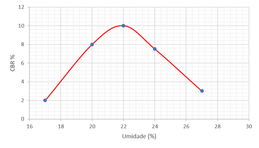
The CBR drops on both sides: below optimum, the dry soil absorbs water during soaking and loses strength; above it, there is too much water in the voids and the density is lower. That is why moisture control on site is as important as the test itself.
How to estimate CBR with the DCP
The dynamic cone penetrometer (DCP), standardized by ASTM D6951/D6951M-18(2023), measures in the field how many millimeters the cone tip penetrates per blow, the DCP index. The US Army Corps of Engineers correlation (Webster et al., 1992), reproduced in the standard, estimates CBR as CBR = 292 / DCP1.12, with DCP in mm/blow: 10 mm/blow gives about 22%, and 25 mm/blow about 8%. The standard itself warns that this equation does not apply to CL clays with CBR below 10 or to CH clays, which have their own equations. The result is an estimated field CBR, at the moisture content of the day, and does not replace the laboratory CBR after 96 hours of soaking.
Worked example: from test specimen to CBR
The example uses the test specimen molded at the optimum moisture content of the soil in the graphs above (w = 22%), compacted with standard (normal) compaction effort, on a press with a load cell. All calculations can be redone by hand.
1. Dry density. The moist soil compacted in the mold weighs 3,943 g, in a volume of 2,085 cm³. So ρh = 3,943 / 2,085 = 1.891 g/cm³ and ρs = 1.891 / 1.22 = 1.550 g/cm³. This is the peak of the compaction curve, as expected at optimum moisture content.
2. Swell. The swell dial gauge read 1.20 mm at the start of soaking and 1.54 mm after 96 hours. Swell = (1.54 − 1.20) / 114.3 × 100 = 0.34 / 114.3 × 100 = 0.30%.
3. Pressures and CBR. The load cell read 1.30 kN at 2.54 mm and 2.05 kN at 5.08 mm, on a curve with no initial inflection (no correction).
- At 2.54 mm: p = 1,300 / 1,932 = 0.673 MPa; CBR = 0.673 / 6.9 × 100 = 9.8%.
- At 5.08 mm: p = 2,050 / 1,932 = 1.061 MPa; CBR = 1.061 / 10.35 × 100 = 10.3%.
4. Result. Under DNIT 172/2016-ME and NBR 9895, the higher value is adopted, CBR = 10.3%, which the report rounds to 10%, with a swell of 0.3%. Under ASTM D1883, since the 5.08 mm value is higher, the test would be repeated before adopting 10.3%.
5. Interpreting the result. With a CBR of 10% and swell of 0.3%, the soil meets the subgrade requirements (CBR ≥ 2% and swell ≤ 2%) and can be used as a subgrade improvement layer over a weaker subgrade, but it is not suitable as subbase, which requires CBR ≥ 20%. The maximum force measured, 2.05 kN, is about 4% of the capacity of a 50 kN load cell, and the forces for a base course material with a CBR of 80% approach 16 kN at 5.08 mm: the same load cell covers both cases.
How to interpret the CBR test result
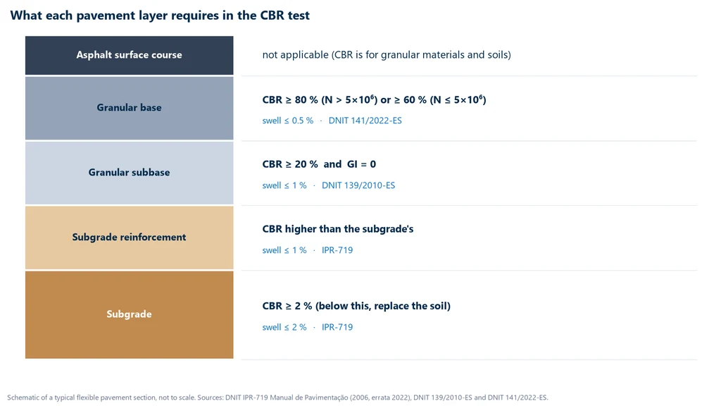
CBR has no absolute good or bad value. It is compared with the requirement of the layer where the material will be used, and always together with swell. The requirements come from the Pavement Manual of DNIT, Brazil's National Department of Transport Infrastructure (IPR-719, 3rd edition, 2006), and from the construction specifications for subbase and base. The diagram below summarizes what each layer requires:
What is the ideal CBR?
There is no single ideal CBR: the required value depends on the layer. A granular base requires a CBR of at least 80% (or 60% with N up to 5 × 10⁶) and swell up to 0.5%; a subbase, CBR of 20% and swell up to 1%; the subgrade, CBR of 2% and swell up to 2%. The limits come from DNIT 141/2022-ES, DNIT 139/2010-ES and IPR-719, and are detailed below.
What is the minimum subgrade CBR?
IPR-719 requires the subgrade to have CBR ≥ 2% and swell ≤ 2%. With CBR below 2%, the manual recommends replacing the soil to a depth of at least 1 m with material having a CBR above 2%. Within these limits the subgrade is accepted, and its CBR is the value that governs the total pavement thickness: the lower the CBR, the thicker the pavement.
What is the ideal CBR for a base?
For a granular (mechanically stabilized) base, DNIT 141/2022-ES requires CBR ≥ 80% when the number N of standard axle load repetitions exceeds 5 × 10⁶, and CBR ≥ 60% when N ≤ 5 × 10⁶, with maximum swell of 0.5%, liquid limit ≤ 25% and plasticity index ≤ 6% (the Manual accepts LL and PI above these values when the sand equivalent is greater than 30). A granular subbase, under DNIT 139/2010-ES, requires CBR ≥ 20%, group index equal to zero and swell ≤ 1%. Subgrade reinforcement needs a CBR higher than that of the subgrade and swell ≤ 1%. In DNIT 141/2022-ES, the minimum base CBR applies when the pavement was designed by the empirical method; in mechanistic design, the base is controlled by resilient modulus and permanent deformation, and the 0.5% swell limit still applies.
What does swell tell you about the soil?
Swell measures how much the soil expands when it takes up water under the surcharge. A high value indicates expansive clay minerals or an unstable structure, and such soil tends to heave and lose support in the pavement during the rainy season. That is why the specification is twofold: a material with a CBR of 25% and swell of 1.5% is not acceptable as subbase. For lateritic soils, DNIT 139/2010-ES accepts a nonzero group index and swell above 1% in the subbase, provided the expansibility test gives less than 10%.
What CBR values are typical for each soil type?
There are published ranges by Unified Soil Classification System (USCS) class that help judge whether a result is plausible. The ranges in the table come from Pavement Interactive, which cites the WSDOT pavement guide, and are North American: they are for guidance only and do not replace the test. Tropical lateritic soils often fall outside them, with a high CBR for their fines content.
| USCS class | Description | Typical CBR |
|---|---|---|
| GW | Well-graded gravel | 40 to 80% |
| GP, GM | Poorly graded or silty gravel | 20 to 60% |
| GC, SW | Clayey gravel; well-graded sand | 20 to 40% |
| SP, SM | Poorly graded or silty sand | 10 to 40% |
| SC | Clayey sand | 5 to 20% |
| ML, CL, CH | Silts and clays | up to 15% |
| MH | High-compressibility silt | up to 10% |
| OL, OH | Organic soils | up to 5% |
Does a high CBR guarantee a good pavement?
Not on its own. The CBR is valid for the moisture content and density of the test, and the layer will only have that support if it is built with the same compaction energy and close to the optimum moisture content. In addition, two soils with the same CBR can have very different stiffness under repeated loading, which is what traffic applies. That is why mechanistic design uses another parameter, as the next section shows.
Does the laboratory CBR apply in the field?
Not directly. The laboratory CBR is measured after 96 hours of soaking, with the soil close to saturation, which is the most unfavorable condition expected in service. In the field, the soil is at its current moisture content, so the two values cannot be compared one to one. The ASTM in-situ CBR method, D4429, was withdrawn in 2018 with no replacement; in the field, the usual approach is to estimate the CBR with the DCP, as shown in the calculation section, bearing in mind that the number obtained is a field value and does not replace the design CBR.
CBR in pavement design: the DNER method and MeDiNa
In the DNER flexible pavement design method (DNER is the former Brazilian federal highway department), adopted in IPR-719, the total pavement thickness needed to protect a layer is read from a chart as a function of the number N (repetitions of the 8.2 t standard single axle over the design period) and the CBR of the layer. The manual gives the equation of the chart:
H = 77.67 × N0.0482 × CBR−0.598 (H in cm, in terms of granular material)
Hm is the thickness above the subgrade (CBR = m), Hn above the reinforcement and H20 above the subbase, which is always treated as CBR 20, even when the measured value is higher. The actual thicknesses come from the inequalities R·KR + B·KB ≥ H20, R·KR + B·KB + h20·KS ≥ Hn and R·KR + B·KB + h20·KS + hn·KRef ≥ Hm; without reinforcement, the second is compared directly with Hm, as in the example below. The structural equivalence coefficients K are 2.00 for an asphalt concrete surface course and 1.00 for granular layers.
Example. The subgrade is the soil from the worked example, CBR = 10%, and the traffic is N = 2 × 10⁶.
- N0.0482 = 106.301 × 0.0482 = 100.3037 = 2.012.
- Hm = 77.67 × 2.012 × 10−0.598 = 77.67 × 2.012 × 0.2523 = 39.4 cm.
- H20 = 77.67 × 2.012 × 20−0.598 = 77.67 × 2.012 × 0.1667 = 26.1 cm.
- Surface course: for 106 < N ≤ 5 × 10⁶, IPR-719 requires a 5.0 cm asphalt surface course, so R·KR = 5 × 2 = 10 cm.
- Base: B ≥ 26.1 − 10 = 16.1 cm; B = 17 cm is adopted.
- Subbase: h20 ≥ 39.4 − 10 − 17 = 12.4 cm; since the minimum constructible thickness of a granular layer is 15 cm, h20 = 15 cm is adopted.
The structure has 5 cm of surface course, 17 cm of base and 15 cm of subbase. If the subgrade had a CBR of 5%, Hm would rise to 77.67 × 2.012 × 5−0.598 = 59.7 cm, and the subbase would increase to about 33 cm. Doubling the subgrade CBR saves about 18 cm of granular material, which shows why the test must be done well.
DNIT has made MeDiNa (Brazil's National Pavement Design Method) official. It is a mechanistic-empirical method, governed by service instruction IS-247. In it, materials are characterized by resilient modulus (DNIT 134/2018-ME), obtained in the repeated-load triaxial test, and by permanent deformation (DNIT 179/2018-IE). CBR has not left routine practice: layer specifications still require swell according to DNIT 172/2016-ME, and CBR remains the reference when the design is empirical and in borrow source selection. What MeDiNa does not accept is estimating the resilient modulus from the CBR, because the correlation between the two is weak.
Common mistakes in the CBR test
Most discrepancies between laboratories come from details of test execution, not from the calculation. The mistakes below are the ones that change the result the most:
- Shortening the soaking period or forgetting the surcharge. Without the 4 days of soaking and without the surcharge of about 4.54 kg, the specimen does not reach the design moisture condition, and the CBR comes out too high.
- Penetration rate other than 1.27 mm/min. On a manual press, turning the crank faster or slower changes the measured resistance and invalidates the comparison with the standard pressure.
- Not correcting a curve with an inflection. The CBR is underestimated, as in the example in the graph, where the result would drop from 20.3% to 18.4%.
- Mixing the NBR rule with the ASTM rule. Adopting the higher value and citing ASTM D1883 in the report, or the other way around, gives a result inconsistent with the declared standard.
- Inverting the formula. The soil pressure goes in the numerator and the standard pressure in the denominator. The inverted ratio, which circulates on some web pages, gives values above 100% precisely for the weakest soils.
- Using the wrong piston area. The piston in DNIT 172/2016-ME and NBR 9895:2025 (the Brazilian CBR test standard) is 49.6 mm, or 19.32 cm². Using 50 mm (19.64 cm²) reduces the calculated pressure by about 1.6%.
- Mixing units in the conversion. If the soil pressure is calculated in MPa from the force in newtons, the standard pressure must be in exact MPa (6.9 and 10.35); converting it with the note in DNIT 172/2016-ME (1 kgf/cm² = 0.1 MPa) shifts the CBR by about 2%. With both pressures in kgf/cm², the problem does not exist.
- Reusing the sample. The method uses an unworked sample; soil that has already been compacted has broken grains and gives a different result.
- Testing at one compaction energy and building at another. The CBR at 26 blows does not apply to a layer compacted with standard energy.
- Forgetting to replace the fraction above 19 mm. Large stones in the mold make the piston hit a grain, and the reading jumps. Under NBR 9895:2025, material with more than 30% retained on the 19 mm sieve is outside the scope of the method.
- Using a table of typical CBR values instead of the test. Ranges by soil class are for checking plausibility, not for design.
- Citing outdated standards or attributing the compaction test to NBR 6457, when it is covered by NBR 7182 (the Brazilian Proctor compaction standard).
CBR test press: manual and automatic electric
Biopdi manufactures the CBR/Marshall test press in two versions, manual and automatic electric, and both perform the CBR test and the Marshall test; the automatic version also performs the consolidation test, with the 2" and 3" cells. The figures below show each version with its components: on the manual press, the proving ring with the dial gauge that reads the load, the penetration dial gauge, the CBR fixture and the manual drive; on the automatic press, the load cell, the LVDT, the touchscreen display, the CBR fixture and the electronic panel.
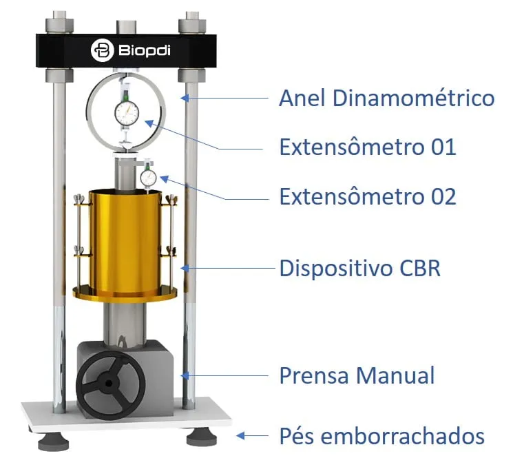
Manual CBR press
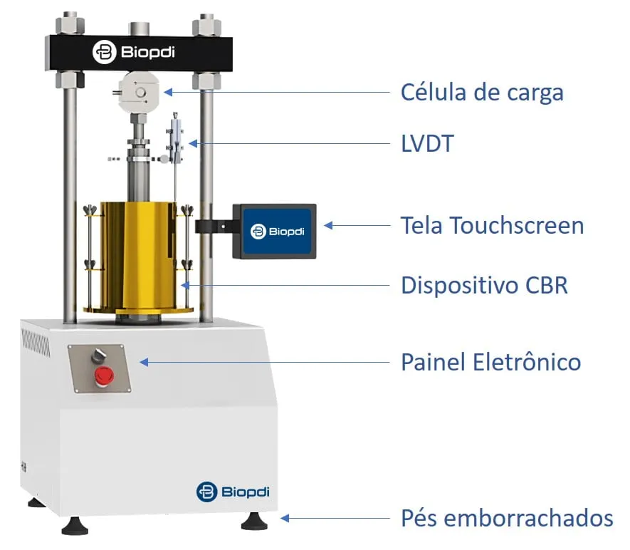
Automatic CBR press
The manual version uses a proving ring of 500 to 5,000 kgf (4.9 to 49 kN) and a dial gauge, and can be upgraded to a load cell and touchscreen display. The automatic electric version is electromechanical, with a recirculating ball screw and microprocessor control, and it is the one detailed item by item in the panel below, against what the test requires:
The CBR/Marshall press in the CBR test
The automatic electric press has a capacity of 50 kN (11,240 lbf), the same as the proving ring assembly required by DNIT 172/2016-ME. Each part has a role in the test:
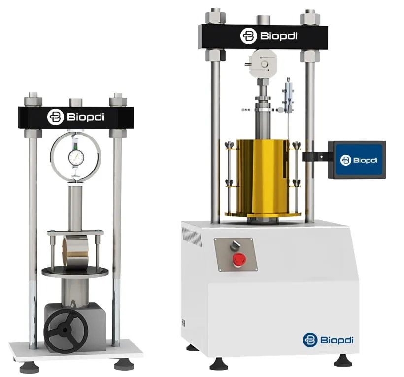
- Speed control from 0.001 to 50 mm/min, covering the 1.27 mm/min of the CBR test and the 50 mm/min of the Marshall test
- Load cell interchangeable, from 5 to 5,000 kgf (0.049 to 49 kN)
- LVDT 50 mm, 0.01 mm resolution, measures penetration; the encoder reads actuator displacement with 0.001 mm
- Touchscreen display force reading at the 14 penetrations of NBR 9895, graph and recording to SD card
- 100 mm stroke and 300 mm between columns
- Safety emergency stop button, upper and lower limit switches and automatic stop by force or displacement
Fixtures for the CBR test
The fixtures below are mounted on the same press:
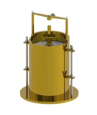 CBR fixtureCBR test assembly
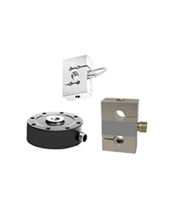 Load cell5 to 5,000 kgf
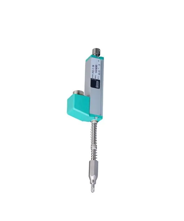 LVDTlinear displacement, 0.01 mm
In practice, the automatic press eliminates three of the common mistakes: it holds the 1.27 mm/min rate without depending on the operator, records the whole curve instead of nine or fourteen readings, which makes the inflection point correction easier, and delivers the graph and report without manual transcription. The 0.01 mm resolution of the LVDT matches the graduation that DNIT 172/2016-ME requires for the penetration dial gauge. For the resilient modulus and permanent deformation used in MeDiNa, the equipment is the dynamic triaxial testing system; our other equipment is listed under soil testing.
Videos about the CBR/Marshall press: automatic electric
The videos below present the automatic electric CBR/Marshall press and its main features: fixture setup, the touchscreen display and running the test.
Conclusion
The CBR test delivers a simple number, a percentage, but that number carries the result of three linked stages: compaction at the correct energy, four days of soaking to measure swell and, only then, penetration. Skipping or shortening any of them produces a value that does not represent how the soil behaves in service, and it is on that value that layers are accepted and the pavement is designed. In the calculation, the points that matter most are the correction of a curve with an inflection and the rule of adopting the higher of the CBR values at 2.54 and 5.08 mm.
The other soil tests have their own articles: the consolidation test, the direct shear test and the triaxial test. If you need more information about the test or about the right equipment for your laboratory, talk to one of our specialists.
Other tests and technical references
Marshall test: stability, flow, Vv, VMA (VAM) and VFA (RBV) per DNIT 447/2024-ME
The Marshall test measures the stability and flow of asphalt mixtures at 60 °C per DNIT 447/2024-ME. Procedure, Vv, VMA, VFA and a worked example.
Direct shear test: ASTM D3080 standard, step-by-step procedure and how to calculate c' and φ'
The direct shear test measures soil shear strength and gives the cohesion c' and friction angle φ'. ASTM D3080-23, step by step, with a worked example.
Soil compaction and the Proctor test per ABNT NBR 7182:2025
Soil compaction on site and the Proctor test per NBR 7182:2025: compaction energies, worked curve example, optimum moisture content and degree of compaction.
Soil particle size analysis: sieve and hydrometer test and gradation curve per NBR 7181
Soil particle size analysis per NBR 7181:2025: sieving, hydrometer sedimentation, gradation curve, D10, Cu and Cc, NBR 6502 fractions, worked example.
Frequently asked questions
What is the CBR test or California Bearing Ratio?
It is the test that measures the pressure needed for a 49.6 mm piston to penetrate a compacted soil soaked for 4 days, as a percentage of the pressure that penetrates a standard crushed stone: 6.9 MPa at 2.54 mm and 10.35 MPa at 5.08 mm. CBR (California Bearing Ratio) and ISC (Índice de Suporte Califórnia, its Portuguese name in Brazil) refer to the same test and the same number.
What does a CBR value of 15% mean?
It means that the penetration resistance of the tested soil equals 15% of the resistance of the standard crushed stone used as the reference. The higher the percentage, the higher the bearing capacity of the soil and the thinner the pavement needed on top of it.
What is CBR in engineering?
In engineering, the CBR (ISC in Brazil) is the soil bearing capacity index used in pavement engineering for two purposes. It is used to accept subgrade, subgrade reinforcement, subbase and base materials, which have a minimum CBR and a maximum swell in the specifications of DNIT (Brazil's National Department of Transport Infrastructure). It is also used to design flexible pavements by the DNER method (from Brazil's former National Highway Department), in which the subgrade CBR and the traffic define the total thickness.
What is the standard for the CBR test?
In Brazil, the standards are ABNT NBR 9895:2025 (the Brazilian standard for the CBR test) and DNIT 172/2016-ME, which replaced DNER-ME 049/94. Sample preparation follows ABNT NBR 6457:2024, and compaction follows ABNT NBR 7182:2025, DNIT 164/2013-ME or DNER-ME 162/94. The international reference is ASTM D1883-21.
How is the CBR test performed?
The CBR test is performed in three steps, in this order. First, the test specimens are compacted at increasing moisture contents, with at least five specimens. Next, they are soaked in water for 96 hours to measure swell. Finally, they are penetrated in the press at 1.27 mm/min. Each step produces its own graph: dry density versus moisture content, swell versus moisture content, and pressure versus penetration, which gives the CBR.
How do you calculate the CBR?
Divide the force by the piston area (19.32 cm², or 1,932 mm²) to obtain the pressure at 2.54 and 5.08 mm, corrected when the curve has an inflection. Then apply CBR (%) = pressure / standard pressure × 100, with 6.9 MPa and 10.35 MPa. Under NBR 9895:2025 and DNIT 172/2016-ME, the higher of the two values is adopted.
What if the CBR at 5.08 mm is higher than at 2.54 mm?
Under DNIT 172/2016-ME and NBR 9895:2025, the higher value is adopted and the test is not repeated. The rule to repeat comes from ASTM D1883. That standard reports the 2.54 mm value, and if the 5.08 mm value is higher, the test must be repeated. If the result is confirmed, the 5.08 mm value is used. That is why the test report must state which standard was followed.
What is the ideal CBR?
There is no single ideal CBR because it depends on the layer. For a granular stabilized base, DNIT 141/2022-ES requires CBR ≥ 80% when N > 5 × 10⁶ and CBR ≥ 60% when N ≤ 5 × 10⁶, with swell ≤ 0.5%. The subbase requires CBR ≥ 20% and swell ≤ 1% (DNIT 139/2010-ES). The subgrade requires CBR ≥ 2% and swell ≤ 2% (IPR-719, DNIT's pavement manual).
What is the difference between the compaction test and the CBR test?
They are two measurements on the same test specimens. Compaction is done in the CBR mold with the compaction energies of NBR 7182:2025 (the Brazilian Proctor compaction standard). It produces the curve of dry density versus moisture content, which gives the optimum moisture content. For the CBR, these same specimens are soaked for 96 hours and then penetrated. DNIT 172/2016-ME reads the soil CBR at the optimum moisture content, while NBR 9895:2025 reads it according to the design criterion.
Can the CBR be calculated with the DCP?
It can be estimated. The correlation reproduced in ASTM D6951/D6951M is CBR = 292 / DCP raised to the power 1.12, with the DCP index in mm/blow. For example, 10 mm/blow gives about 22%. It does not apply to CL clays with CBR below 10 or to CH clays. This gives a field CBR at the moisture content on the day of the test. It does not replace the laboratory CBR measured after 96 hours of soaking.
What is standard Proctor?
Standard Proctor is the standard compaction energy. In the CBR mold, it corresponds to 12 blows per layer of the 4.536 kg rammer dropped from 457.2 mm, in 5 layers. The intermediate energy uses 26 blows, and the modified energy (modified Proctor) uses 55. DNIT 172/2016-ME assigns the three energies to the subgrade, the subbase and the base.
What is the difference between a manual and an automatic CBR press?
With a manual press, the operator has to keep the penetration rate steady and take the load and displacement readings. An automatic press controls the rate electronically and records the data points in software. This removes operator-to-operator variation and produces the graph and the report without manual transcription.