
The shear modulus (G), also called the modulus of rigidity or transverse modulus of elasticity, measures a material's stiffness against distortion. It is the ratio of shear stress to shear strain (in radians) in the elastic range: G = τ/γ. For structural steel, ABNT NBR 8800 (the Brazilian standard for the design of steel structures) uses G = 77,000 MPa (77 GPa). In an isotropic material, G can be calculated from Young's modulus and Poisson's ratio as G = E/[2(1 + ν)], so it always falls between E/3 and E/2.
In short:
- Formula: G = τ/γ, with τ in MPa and γ in radians. G comes out in the unit of stress, which is GPa for metals.
- Reference values: steel 77 GPa (NBR 8800) and 75 to 83 GPa in handbook tables; aluminum 25 GPa; copper 46 GPa; C30 concrete about 11 GPa (NBR 6118); rubber on the order of megapascals.
- Relationship with E and ν: G = E/[2(1 + ν)], valid only for isotropic materials. With ν = 0.3, G ≈ 0.385·E.
- Measurement: from the slope of the torque vs. angle curve in a torsion test (ASTM E143-20), by vibration (ASTM E1876-22) or, for composites, with V-notched specimens (ASTM D5379 and D7078).
This article treats the modulus as a material property: what it is, where its relationship with E and ν comes from, which values to use in design, how it is measured and where it drives a calculation. Shear testing of pins, adhesives and composites is covered in shear testing, and the step-by-step torsion test procedure in torsion testing.
What is the shear modulus
A force can act on a face in two ways. Perpendicular to the face, it pulls or pushes, and the material responds by lengthening or shortening; the stiffness against this is the modulus of elasticity E. Parallel to the face, it tries to make the layers of the material slide over one another. This is shear loading, and the corresponding stress is the shear stress, τ = F/A: the parallel force divided by the area of the face on which it acts.
Under shear, the material does not change length: it changes shape. A cube becomes a slanted parallelepiped, and the right angle between two edges gets smaller. This change in angle is the shear strain, or angular distortion, γ. If the top face of a block of height h moves Δx relative to the bottom face, γ ≈ Δx/h, in radians. The shear modulus is the constant that links these two quantities while the material behaves like a spring: τ = G·γ. It is Hooke's law written for shear.
The diagram below shows both side by side. On the left, the block with its base fixed and the force F applied to the top face: the displacement Δx, the height h and the angle γ that measures the distortion. On the right, the τ vs. γ curve of a steel, with the initial straight portion whose slope is G, the point where the straight line ends, and shear yielding at around 144 MPa for a steel with a tensile yield strength of 250 MPa.
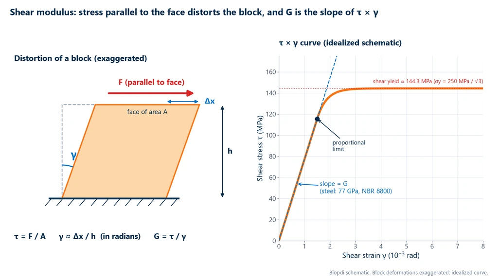
The curve is read the same way as the stress-strain curve from a tensile test. G applies only to the straight portion, up to the proportional limit; beyond it the curve bends and part of the strain becomes permanent. The G of a steel is about 2.6 times lower than its E: under the same stress, steel distorts more than it stretches.
Different names for the same property
"Shear modulus", "transverse modulus of elasticity" and "modulus of rigidity" designate the same quantity G. Brazilian design standards such as NBR 8800 and NBR 6118 use "módulo de elasticidade transversal" (transverse modulus of elasticity); the materials literature and ASTM standards use "shear modulus"; "modulus of rigidity" is common in mechanical engineering tables. Older texts also refer to the "Coulomb modulus" or "torsional modulus", and in Portugal it is called "módulo de corte". The symbol is always G; the letter E is reserved for Young's modulus and K for the bulk modulus.
Stiffness is not strength
The shear modulus tells how much a material distorts under a given stress, not how much stress it can withstand. The maximum stress a material can carry in shear is its shear strength, in MPa, measured in a shear test. The two quantities are independent: a mild steel and a quenched steel have practically the same G, around 77 to 80 GPa, and shear strengths that differ several times over. Heat treatment, work hardening and carbon content change strength a great deal and stiffness hardly at all, just as with Young's modulus.
Material modulus vs. component stiffness
G is a material property and does not depend on the shape of the part. When a shaft is twisted, what the designer feels is the torsional stiffness, k = G·J/L, in N·m/rad: the torque needed to rotate the part by one radian. It combines the material (G), the cross-section (the polar moment of inertia J) and the length (L). Two shafts of the same steel, one solid and one tubular, have the same G and very different torsional stiffnesses. Confusing the two is one of the most common mistakes in torsion test reports, because the slope of the torque vs. angle curve is G·J/L, not G.
Shear modulus formula and units
The definition is written in three steps. The stress is τ = F/A, in N/mm², which is the same as MPa. The shear strain is γ ≈ Δx/h, a ratio of two lengths and therefore dimensionless; the approximation holds because, at the small angles of the elastic range, the angle in radians and its tangent are practically equal. The modulus is G = τ/γ and has the unit of stress.
The radian is not a mere notational detail. It is the angle measured as the ratio of arc to radius, which is why the shear strain comes out as Δx/h. Writing the shear strain in degrees multiplies the denominator by 180/π = 57.3, and the calculated G comes out 57.3 times smaller than the real value: a 79 GPa steel starts to look like a 1.4 GPa polymer (exercise 3). Every formula involving an angle in this subject, whether γ or the angle of twist θ, uses radians.
For metals, G is written in GPa (77 GPa) or in MPa (77,000 MPa), as NBR 8800 does. Older design reports use kgf/cm²: 77,000 MPa is about 7.85 × 10⁵ kgf/cm², with 1 kgf/cm² = 0.0980665 MPa. In kN/cm², a unit used by some structural design programs, it is 7,700 kN/cm². For elastomers the value is so low that MPa is used directly. The table summarizes the defining formulas and those that carry G over to the component:
| Quantity | Formula | Unit and validity |
|---|---|---|
| Average shear stress | τ = F / A | MPa; F parallel to the face of area A |
| Shear strain | γ ≈ Δx / h | rad; small strains |
| Shear modulus | G = τ / γ | GPa; linear portion only |
| Relationship with E and ν | G = E / [2(1 + ν)] | isotropic materials only |
| Angle of twist of a circular shaft | θ = T·L / (G·J) | rad; elastic range |
| G measured by torsion | G = (ΔT / Δθ)·L / J | slope of the linear portion |
Relationship between E, G and ν: G = E/[2(1 + ν)]
In an isotropic material, with the same properties in all directions, the shear modulus is not an independent constant: it is determined by Young's modulus E and Poisson's ratio ν. The relationship is G = E/[2(1 + ν)], and it is what allows design standards to give G without requiring a torsion test. Understanding where it comes from also shows when it stops being valid.
The derivation in four steps
The diagram below follows the reasoning from left to right. First, a square in pure shear: the stresses τ on its four faces turn it into a rhombus, and one diagonal lengthens while the other shortens. Next, the same stress state seen on a square rotated by 45°: on the faces of this square there is no shear, only tension σ1 = +τ in one direction and compression σ2 = −τ in the other. Finally, the calculation linking the two views, which the list below the diagram details step by step.
![Three-part diagram: a square in pure shear that becomes a rhombus with its diagonal lengthened; the same state seen at 45 degrees, with tension σ1 = +τ along one diagonal and compression σ2 = −τ along the other; and the calculation that equates the diagonal strain γ/2 with the generalized Hooke's law strain τ(1 + ν)/E, leading to G = E/[2(1 + ν)]](/artigos/modulo-de-cisalhamento/modulo-de-cisalhamento-deducao-g-e-nu-cisalhamento-puro-en.webp)
- Generalized Hooke's law on the tensioned diagonal. The strain in direction 1 has two parts: the elongation caused by σ1 and the extra elongation caused by the compression σ2 in the perpendicular direction, through the Poisson effect. ε1 = (σ1 − ν·σ2)/E = (τ + ν·τ)/E = τ(1 + ν)/E.
- Geometry of the rhombus. When the right angle of a square changes by a small γ, the diagonal lengthens by a fraction γ/2 of its length: ε45° = γ/2.
- Both are the same strain. The diagonal of the original square is direction 1 of the rotated square, so γ/2 = τ(1 + ν)/E.
- Solving for τ/γ: τ/γ = E/[2(1 + ν)], and τ/γ is, by definition, G.
The derivation used a single E and a single ν for directions 1 and 2. That is what restricts the formula to isotropic materials. In fiber composites, wood and rolled sheet with a strong texture, stiffness changes with direction, and the in-plane shear modulus, called G12, is an independent constant that must be measured. Applying the formula to a carbon/epoxy laminate, for example, can be off by a factor of several.
G always lies between E/3 and E/2
In common materials, ν ranges from close to zero, as in cork, to close to 0.5, as in rubber, which barely changes volume. Substituting these extremes into the formula, G ranges from E/2 (ν = 0) to E/3 (ν = 0.5). With ν = 0.3, the design value for steel, G = E/2.6 = 0.385·E; with ν = 0.25, G = 0.4·E; with ν = 0.2, the design value for concrete, G = E/2.4. This is a quick check for any table: in an isotropic material, a G greater than half of E points to a typo or a unit error. The full theoretical range of ν, from −1 to 0.5 and including auxetic materials, is covered in the article on Poisson's ratio.
The same reasoning links G to the bulk modulus K, the stiffness against a change in volume: in an isotropic material, E = 2G(1 + ν) = 3K(1 − 2ν), and any two of these moduli determine the others. For NBR 8800 steel, with E = 200 GPa and ν = 0.3, K = 200/[3 × (1 − 0.6)] = 166.7 GPa, more than twice G. In rubber the opposite happens: with ν close to 0.5, K is thousands of times larger than G, and the material barely changes volume, only shape.
Inverted, the same relationship gives Poisson's ratio from two measured moduli: ν = E/(2G) − 1. This is how vibration methods obtain ν without a transverse extensometer, and it is also a way to check whether the E and G on a data sheet are consistent with each other (exercise 1).
Why the formula does not match the tables exactly
Calculated with the formula, the steel in the Callister and Rethwisch table (E = 207 GPa, ν = 0.30) would give 207/2.6 = 79.6 GPa, but the same table lists 83 GPa as measured. For copper and titanium, the calculated value is about 11% below the tabulated one. There are two causes. First, the E, G and ν in tables come from independent measurements, made on samples and alloys that are not the same. Second, a polycrystalline metal is only isotropic on average: the grains are anisotropic crystals, and rolling and drawing orient them, creating texture. The formula is a good estimate, with an error of a few percent for common metals; when a design depends on G more precisely, as with springs and torsion bars, it is measured.
Shear modulus values by material
Values of G span five orders of magnitude, from the stiffest metals to elastomers. The chart below uses a logarithmic scale, in which each division multiplies the value by ten: metals fall between 17 and 160 GPa, concrete is near 11 GPa, rigid polymers are near 1 GPa and rubber is in the megapascal range. For metals, the bars are measured values. For concrete, the bar is the NBR 6118 value (the Brazilian standard for the design of concrete structures) for a C30. For polymers, the bars are estimates calculated from E and ν, and the light band shows the variation between grades.
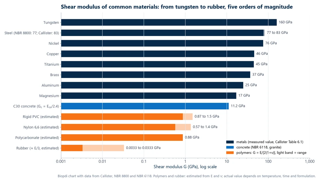
The table lists the metals with all three moduli together, using the same values as the articles on the modulus of elasticity and Poisson's ratio. The steel rows show the three sources of values in circulation: the design standard, the textbook and the datasheet of a specific steel.
| Material | E (GPa) | ν | G (GPa) |
|---|---|---|---|
| Structural steel, design (NBR 8800) | 200 | 0.3 | 77 |
| Steel, textbook value (Callister) | 207 | 0.30 | 83 |
| A36 steel (MatWeb/ASM datasheet) | 200 | 0.26 | 79.3 |
| Tungsten | 407 | 0.28 | 160 |
| Nickel | 207 | 0.31 | 76 |
| Copper | 110 | 0.34 | 46 |
| Titanium | 107 | 0.34 | 45 |
| Brass | 97 | 0.34 | 37 |
| Aluminum | 69 | 0.33 | 25 |
| Magnesium | 45 | 0.29 | 17 |
Sources: ABNT NBR 8800 (the Brazilian standard for the design of steel and composite structures; item 4.5.2.9, checked against the 2008 text); Callister and Rethwisch, Materials Science and Engineering, Table 6.1, for the other metals; MatWeb/ASM datasheet for A36. Some tables on the internet give copper as about 63 GPa, a value incompatible with an E of 110 GPa: according to the formula, no ν between 0 and 0.5 would lead to more than 55 GPa. The measured value lies between 44 and 46 GPa.
Outside metals, the same calculation with the E and ν values from the site's articles gives the order of magnitude: soda-lime glass, with E = 69 GPa and ν = 0.22, has G ≈ 69/2.44 = 28 GPa, almost the same as aluminum, but it fractures without plastic deformation. Wood and fiber composites are left out of this table, because they have a different G for each plane and must be tested (see the section on measurement).
Shear modulus of steel: 77, 80 or 83 GPa?
The shear modulus of steel lies between 77 and 83 GPa, and the three figures most often quoted are all correct, each in its own context. NBR 8800, the Brazilian standard for steel and composite structures, sets E = 200,000 MPa, ν = 0.3 and G = 77,000 MPa; the calculation 200/2.6 = 76.9 GPa shows that the three values are consistent with each other. A designer working to NBR 6118, which adopts E = 210 GPa for reinforcing steel, and applying ν = 0.3, arrives at 210/2.6 = 80.8 GPa. Datasheets for specific steels give 79 to 80 GPa, such as A36 at 79.3 GPa, and Callister lists 83 GPa as a textbook value. Tables that give "80 to 85 GPa" start from E between 207 and 210 GPa. The practical rule is to use G from the same source that provided the E in the calculation. Mixing E = 210 GPa with G = 77 GPa, for example, implies a ν of 0.36, which no steel has. Values of E by type of steel are in the article on the modulus of elasticity of steel.
Shear modulus of concrete: Gc = Ecs/2.4 per NBR 6118
ABNT NBR 6118:2023, in item 8.2.9, allows concrete to be taken as having ν = 0.2 and a shear modulus Gc = Ecs/2.4, provided compressive stresses remain below 0.5 fc and tensile stresses below the tensile strength fct. The 2.4 is not empirical: it is 2 × (1 + 0.2), that is, the same isotropic formula with the ν of concrete. Ecs is the secant modulus, calculated from fck and the aggregate, as shown in the article on the modulus of elasticity of concrete. With granite aggregate, the values are:
| Class | Ecs (GPa) | Gc = Ecs/2.4 (GPa) |
|---|---|---|
| C25 | 24.2 | 10.1 |
| C30 | 26.8 | 11.2 |
| C40 | 31.9 | 13.3 |
The stress condition matters. Above it, concrete microcracks, the cracks open perpendicular to the tension, and shear stiffness drops well below the elastic Gc. That is why the standard's value applies to the calculation of deformations in service, not to behavior close to failure. Generic values such as "concrete = 21 GPa", which appear in foreign tables without a class or aggregate, do not follow NBR 6118 and should not be used in designs in Brazil.
Polymers and rubber
In polymers, G is not a material constant in the same way as in metals. They are viscoelastic: part of the deformation takes time to appear and to disappear, and the measured stiffness depends on temperature, loading time and frequency. Near the glass transition temperature, G can drop a hundredfold over a few tens of degrees. Under oscillating load, the modulus splits into two parts, the complex modulus G* = G' + iG'': G' is the elastic part, the energy stored and returned in each cycle, and G'' is the viscous part, the energy dissipated as heat. This is the output of dynamic mechanical analysis (DMA).
For a design estimate at room temperature, the isotropic formula gives the order of magnitude with the E and ν values from the site's articles: polycarbonate, with E = 2.38 GPa and ν = 0.36, has G ≈ 0.88 GPa; rigid PVC, with E from 2.41 to 4.14 GPa and ν = 0.38, falls between 0.87 and 1.5 GPa; nylon 6,6, with E from 1.59 to 3.79 GPa and ν = 0.39, between 0.57 and 1.4 GPa. In rubber, with ν close to 0.5, G ≈ E/3; for the E range of 0.01 to 0.1 GPa, this gives roughly 3 to 33 MPa. Soft compounds fall below this range: the AASHTO LRFD bridge design specification gives, for the common elastomers used in bridge bearings, with a hardness of 50 to 60 Shore A, G between 0.55 and 1.2 MPa (0.080 to 0.175 ksi), and the classic table by Crandall, Dahl and Lardner (An Introduction to the Mechanics of Solids) gives 0.3 MPa for soft rubber. In elastomers, the value depends heavily on the hardness and formulation of the compound, and the component manufacturer should provide G measured at the service temperature.
How shear modulus is measured
Measuring G means measuring a shear stress and a shear strain at the same time, on the specimen itself, within the linear range. The methods differ in how they create the shear: twisting a bar, torsional vibration, a notched specimen that concentrates shear on one plane, or a wave traveling through the sample. A simple tensile test does not give G: it gives E, and only with ν measured in the same test, and for an isotropic material, can G be estimated from the formula.
Torsion test (ASTM E143)
Twisting a circular bar is the cleanest way to obtain pure shear, because every point on the surface is under τ with no normal stress. ASTM E143-20 standardizes the determination of G by torsion, at room temperature, for structural materials in which creep is negligible during the test. The method applies increasing torque and records the angle of twist between two sections of the gauge length; G is obtained from the slope of the straight portion of the torque × angle curve, G = (ΔT/Δθ)·L/J, where J = π·d⁴/32 is the polar moment of inertia of the solid section.
The photo shows a steel bar after a torsion test: the line that was painted straight along its length has become a helix. The angle this line makes with the axis is the shear strain, and it is used to calculate the modulus G.

At the surface, this shear strain is γ = r·θ/L, with r the radius, θ the angle of twist and L the length between the measured sections. It is zero at the center and maximum at the surface, as is the stress, and the ratio between the two is G at any radius as long as the material remains elastic. The specimen, gripping, speed and reading of the curve up to fracture are covered in the article on the torsion test; for the modulus, four precautions determine the result:
- Slope, not a single point. ASTM E143 obtains G from the slope of the linear portion, fitted to several points. A single point carries the seating angle of the grips at the start of the test and can be off by a few percent (exercise 2).
- Angle over the gauge length. Chuck rotation adds grip backlash and the deformation of the load train. For G, the angle is measured between two sections of the specimen or corrected for the system stiffness.
- Measured diameter. The diameter enters J to the fourth power: a 1% error in diameter becomes about a 4% error in G.
- Alignment and material condition. The standard lists residual stresses, concentricity, wall thickness of tubes, temperature and axial alignment as factors that affect the result. For tubes, J = π·(D⁴ − d⁴)/32, and the wall thickness must be measured.
Impulse excitation (ASTM E1876)
ASTM E1876-22 obtains dynamic E, G and ν without loading the part to test stresses: a rectangular or cylindrical bar receives a light tap, and a sensor picks up its natural vibration frequencies. The flexural frequency gives E; the torsional frequency gives G; ν comes from ν = E/(2G) − 1. The method is fast, repeatable and non-destructive, which is why it is used for quality control of ceramics, refractories and metals; the distinction between tests that consume the sample and those that preserve it is covered in destructive and non-destructive testing. The dynamic value need not match the static one, especially in polymers and concrete, and a specification that calls for a static value must be followed.
Composites: V-notch (ASTM D5379 and D7078)
In a fiber laminate, G12 has to be measured, because the isotropic formula does not apply. The two most widely used methods concentrate shear in a region between two V-notches. In ASTM D5379, the specimen is a beam loaded at its edges (Iosipescu method); in ASTM D7078, it is clamped by its faces in two rails, which allows higher forces and a larger gauge area. In both cases, two strain gauges bonded at +45° and −45° at the center of the specimen give the shear strain, γ = ε+45 − ε−45, and the result is a chord modulus between two strain levels, valid only for the plane tested. The fixture is mounted on a universal testing machine; details of the test are in the article on the shear test.
Other tests on the universal testing machine: ±45°, quadruple shear and sandwich core
Three other methods obtain G from an ordinary tensile or compression test, with the right fixture and strain measurement on the specimen. In ASTM D3518/D3518M, a laminate with fibers at +45° and −45° is pulled in tension; the in-plane shear stress is half the axial stress, τ12 = P/(2A), the shear strain is the sum of the magnitudes of the longitudinal and transverse strains, γ12 = εx − εy, and G12 comes from the slope of τ12 × γ12. It is the simplest route for composites, because it uses the straight tensile specimen. In ISO 1827, four rubber blocks bonded between rigid plates are sheared at the same time; the modulus comes from the force and the displacement of the plates, and the same arrangement measures the adhesion of rubber to metal. In ASTM C273/C273M, the core of a sandwich panel, such as foam or honeycomb, is bonded between two plates that slide past each other, and the test gives the shear modulus and shear strength of the core.
Polymers: DMA
In polymers and elastomers, the G that matters for design is the one at the service temperature and frequency. Dynamic mechanical analysis applies a small oscillating strain, in torsion or shear, and measures G' and G'' over a temperature or frequency sweep; the methods are collected in the ISO 6721 series. The result shows where the material softens, and is more useful than a single table value.
Soils: G0 by bender elements and resonant column
In soils, G is not constant: it decreases as shear strain increases. The reference value is G0, or Gmax, at small strains, used in seismic design and in machine foundations. In the laboratory, it is obtained with bender elements, small piezoelectric transducers installed at the top and base of a triaxial specimen (ASTM D8295-19): the time the shear wave takes to travel through the sample is measured, and G0 = ρ·Vs², with ρ the density and Vs the wave velocity. The resonant column (ASTM D4015-21) excites the specimen in torsion and gives the curve of G and damping as a function of shear strain. The triaxial test itself is covered in triaxial test, and Biopdi's line of soil testing equipment in triaxial testing system.
The table summarizes the methods, the material each is used for and what it delivers:
| Method | Standard | Typical material | What it delivers |
|---|---|---|---|
| Torsion of a bar or tube | ASTM E143-20 | metals and structural materials | static G from the torque × angle slope |
| Impulse excitation | ASTM E1876-22 | metals, ceramics, refractories | dynamic E, G and ν |
| V-notched beam | ASTM D5379 | fiber composites | chord G12 on one plane |
| V-notched rail | ASTM D7078 | fiber composites | chord G12, larger gauge area |
| Tension of ±45° laminate | ASTM D3518/D3518M | fiber composites | G12 with a straight specimen |
| Quadruple shear | ISO 1827 | rubber | G of the compound and adhesion to metal |
| Core between plates | ASTM C273/C273M | sandwich cores | G and strength of the core |
| DMA | ISO 6721 series | polymers and elastomers | G' and G'' vs. temperature and frequency |
| Bender elements | ASTM D8295-19 | soils | G0 = ρ·Vs² |
| Resonant column | ASTM D4015-21 | soils | G and damping vs. shear strain |
Where shear modulus enters design
G appears whenever a part works in torsion or shear and the deformation, not just the strength, must be controlled:
- Shafts and drive shafts: the angle of twist θ = T·L/(G·J) limits the design by stiffness, because excessive twist misaligns gears and excites torsional vibration. ASTM E143 cites rotating shafts as a typical application of G.
- Helical springs: the wire of a compression spring works in torsion, and the spring rate is k = G·d⁴/(8·D³·n), with d the wire diameter, D the mean coil diameter and n the number of active coils. E does not even appear in the calculation (exercise 5).
- Steel sections: lateral-torsional buckling of beams depends on the torsional stiffness of the section, which is G times the torsional constant of the section. This is where the 77,000 MPa of NBR 8800 enters the design of steel structures.
- Concrete: in deep beams, wall-columns and building cores, shear deformation is no longer negligible compared with bending deformation, and the Gc of NBR 6118 comes into play.
- Elastomeric pads and bearings: here a low G is desirable. A rubber bearing lets the structure move horizontally with little force and isolates vibration; the bearing design starts from the G of the compound.
- Geotechnics: the response of the ground to an earthquake or to machine vibration depends on G0 and on the degradation curve of G with shear strain.
How to interpret the shear modulus
The questions below come up when a value of G comes out of a test, a data sheet or a standard and has to be used in a calculation.
The test gave 79 GPa and the standard says 77 GPa. Is the material out of spec?
No. The 77 GPa in NBR 8800 (the Brazilian standard for the design of steel structures) is a design value, consistent with E = 200 GPa and ν = 0.3. The value measured on a real steel usually falls between 77 and 83 GPa, depending on the alloy and the texture. A difference of 2.6% is within the variation of the material and the measurement uncertainty: an error of 0.01 mm in the diameter of a 6 mm bar alone shifts G by 0.7%. The measured G is used to check the material or for calculations that require precision. Design to the standard still uses 77 GPa.
Can I calculate G from the E of the tensile test?
For a common metal, yes, as an estimate: with the measured E and the ν measured in the same test, or the reference ν of the material, the isotropic formula is off by a few percent. For composites, wood, sheet with strong texture and 3D-printed parts, no: the material is not isotropic and G needs its own test. For polymers, the estimate is valid only at the temperature and rate at which E was measured.
Is the slope of the torque vs. angle curve equal to G?
Not directly. The slope, in N·m/rad, is the torsional stiffness G·J/L of the test specimen. To get G, multiply it by the gauge length and divide by the polar moment of inertia. A report that gives the slope without J and L does not tell you the modulus of the material, and two specimens of the same steel with different diameters give different slopes and the same G.
Does the G on a composite or wood data sheet apply in any direction?
No. An anisotropic material has several shear moduli, one for each plane: G12, G13 and G23 in a laminate, or GLR, GLT and GRT in wood. A value without the plane is useless for design. The V-notched specimen test measures one plane per specimen.
Why does the dynamic G differ from the G measured in torsion?
Because the two methods load the material in different ways. Vibration uses very small, fast strains, with no time for the viscous component or for microslip; the static test takes seconds or minutes. In metals the two readings are usually close; in polymers, concrete and soils, the dynamic value tends to be higher. The design standard or the specification says which one to use.
Do temperature and heat treatment change G?
Heat treatment hardly changes it: G depends on the bonds between atoms, and what heat treatment changes is strength, not stiffness. Temperature does change it: in metals G drops slowly with heating, in the same proportion as E, and in polymers it drops sharply near the glass transition. A handbook value of G applies at room temperature.
Worked examples
The examples follow the order of the article: consistency between E, G and ν, measurement by torsion, the degrees error, and three design applications. The relationships between E, G and ν for steel and aluminum with standard values are already worked out in the articles on Poisson's ratio and modulus of elasticity, and are not repeated here.
Example 1: ν from measured E and G
An impulse excitation (vibration) test on a steel bar gives E = 206 GPa and G = 80.0 GPa. Calculate ν and check what happens if E and G come from different sources.
- ν = E/(2G) − 1 = 206/(2 × 80.0) − 1 = 206/160 − 1 = 1.2875 − 1 = 0.29, a normal value for steel.
- Sensitivity: if G were 79.0 GPa, ν = 206/158 − 1 = 0.304. An error of 1.25% in G changed ν by 0.016, about 6%. A ν calculated this way is very sensitive to the quality of both measurements.
- Mixing sources: E = 210 GPa (NBR 6118, the Brazilian standard for the design of concrete structures) with G = 77 GPa (NBR 8800, the Brazilian steel structures standard) gives ν = 210/154 − 1 = 0.36, outside the range for steels. The number is the sign that the two moduli do not belong to the same data set.
Example 2: G from the slope in the torsion test
A solid steel test specimen with d = 6.00 mm is tested in torsion, with the angle measured between two sections L = 100 mm apart. In the linear region, the record shows T1 = 1.00 N·m at θ1 = 0.62° and T2 = 4.00 N·m at θ2 = 2.33°. Calculate G and compare it with the calculation using only the last point.
- Polar moment of inertia: J = π × 6.00⁴ / 32 = π × 1,296 / 32 = 127.23 mm⁴.
- Increments: ΔT = 4.00 − 1.00 = 3.00 N·m = 3,000 N·mm; Δθ = 2.33 − 0.62 = 1.71° = 1.71 × π/180 = 0.029845 rad.
- Modulus: G = ΔT·L / (J·Δθ) = 3,000 × 100 / (127.23 × 0.029845) = 300,000 / 3.7973 = 79,000 MPa = 79.0 GPa.
- Last point only: θ2 = 2.33° = 0.040666 rad, and G = 4,000 × 100 / (127.23 × 0.040666) = 400,000 / 5.1741 = 77,300 MPa = 77.3 GPa, 2.2% lower. The line does not pass through the origin: the 0.05° of initial seating goes entirely into the single point and cancels out in the difference.
- Elastic range check: τmax = 16·T/(π·d³) = 16 × 4,000 / (π × 216) = 64,000 / 678.58 = 94.3 MPa, below the shear yield strength of a common steel (about 144 MPa for a tensile yield strength of 250 MPa). The shear strain at the surface is γ = τ/G = 94.3 / 79,000 = 1.19 × 10⁻³ rad.
As for uncertainty: an angular resolution of 0.018° is 1.1% of Δθ = 1.71°, and a resolution of 0.005 N·m is 0.17% of ΔT = 3.00 N·m. A longer range, more points in the fit and the diameter measured at several positions reduce the uncertainty. At 4 N·m, the test fits on a 5 N·m torsion testing machine.
Example 3: the degrees error
In Example 2, the technician put Δθ = 1.71 straight into the formula, without converting to radians. What G did he get?
- G = 300,000 / (127.23 × 1.71) = 300,000 / 217.57 = 1,379 MPa = 1.38 GPa.
- Ratio: 79.0 / 1.38 = 57.3 = 180/π. The steel "turned into" a rigid polymer.
A steel G below 70 GPa or above 90 GPa calls for a check of the units before any conclusion about the material.
Example 4: angle of twist of a shaft
A solid steel shaft with d = 40 mm and L = 1.2 m transmits T = 500 N·m. Calculate the angle of twist with G = 77 GPa and with G = 83 GPa, and the maximum stress.
- J = π × 40⁴ / 32 = π × 2,560,000 / 32 = 251,327 mm⁴.
- Torsional stiffness with G = 77 GPa: G·J/L = 77,000 × 251,327 / 1,200 = 1.613 × 10⁷ N·mm/rad = 16.1 kN·m/rad.
- θ = T·L / (G·J) = 500,000 × 1,200 / (77,000 × 251,327) = 6.0 × 10⁸ / 1.935 × 10¹⁰ = 0.0310 rad = 1.78°.
- With G = 83 GPa: θ = 6.0 × 10⁸ / 2.086 × 10¹⁰ = 0.0288 rad = 1.65°, 7.2% less.
- τmax = 16 × 500,000 / (π × 40³) = 8,000,000 / 201,062 = 39.8 MPa, the same in both cases.
The stress does not depend on G; the angle does. In a stiffness-limited design, the choice between the standard value and the measured value changes the result in the same proportion.
Example 5: stiffness of a helical spring
A compression spring has steel wire with d = 2.0 mm, mean diameter D = 20 mm and n = 10 active coils. The wire manufacturer states G = 79 GPa. Calculate the spring rate and the effect of using 77 GPa.
- k = G·d⁴ / (8·D³·n) = 79,000 × 2.0⁴ / (8 × 20³ × 10) = 79,000 × 16 / 640,000 = 1,264,000 / 640,000 = 1.98 N/mm.
- With 77 GPa: 77,000 × 16 / 640,000 = 1.93 N/mm, 2.5% less.
Since k is proportional to G, the choice of G value alone uses up a large part of the stiffness tolerance of a precision spring. That is why spring manufacturers work with the G of the wire they buy, not with a generic value.
Example 6: G of a C30 concrete per NBR 6118
Estimate the shear modulus of a C30 concrete with granite coarse aggregate and the shear strain under a service shear stress of 1.0 MPa.
- From the article on the modulus of elasticity of concrete: Eci = 5,600 × √30 = 30,672 MPa; αi = 0.8 + 0.2 × 30/80 = 0.875; Ecs = 0.875 × 30,672 = 26,838 MPa.
- Gc = Ecs / 2.4 = 26,838 / 2.4 = 11,183 MPa ≈ 11.2 GPa.
- Check: Ecs / [2 × (1 + 0.2)] gives the same value, because 2.4 = 2 × 1.2.
- Shear strain: γ = τ/Gc = 1.0 / 11,183 = 8.9 × 10⁻⁵ rad.
Concrete has about one seventh of the G of steel (77 / 11.2 = 6.9). The value only holds while stresses remain within the limits of clause 8.2.9 of the standard.
Common mistakes
The mistakes below show up in test reports, design calculations and exercises:
- Using degrees for γ or θ: G comes out 57.3 times too small.
- Calling the torque vs. angle slope G: it is G·J/L, the stiffness of the part.
- Confusing modulus with shear strength: one is stiffness, in GPa; the other is a fracture or yield stress, in MPa. The bolt shear fixture measures the second.
- Mixing sources: E from one standard with G from another gives an impossible ν.
- Applying G = E/[2(1 + ν)] to composites or wood.
- Calculating G from a single point instead of the slope over several points.
- Measuring outside the linear region or on a material that creeps during the test, a condition that ASTM E143 excludes.
- Measuring the angle from grip rotation without correcting for system compliance.
- Treating the G of a polymer as a constant, without temperature or loading time.
- Using the G0 of a soil for large strains, where G has already dropped.
Equipment for measuring the shear modulus
To measure G by torsion, Biopdi manufactures the torsion testing machine, with capacities of 1, 5 and 10 N·m (others on request), adjustable speed from 0.01 to 200 rpm, angular accuracy of 0.018° and torque accuracy of 0.005 N·m. It accepts specimens up to 200 mm long and diameters from 1 to 8 mm and from 5 to 20 mm, the range of the 6 mm specimen in Example 2. The photos below show the two versions: on the left, the Complete version, which runs standalone, with a display and keypad console and data acquisition software; on the right, the Basic version, with the motor and the two chucks on a base with a rail, used together with the Biopdi universal testing machine.
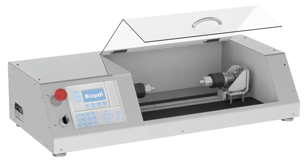
Complete version: standalone operation
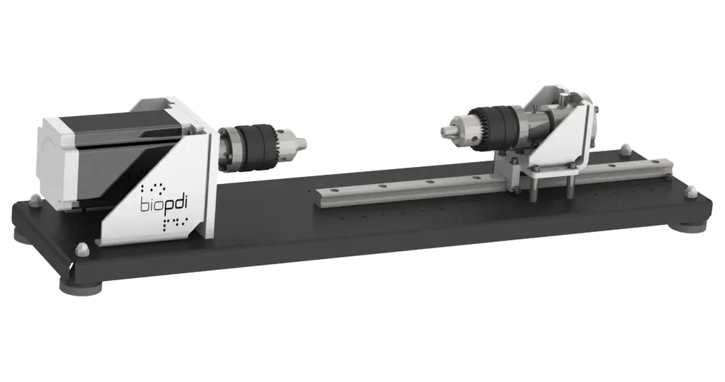
Basic version: used together with the universal testing machine
The universal testing machine contributes to the measurement of G in two ways. First, it measures the inputs to the isotropic formula: Young's modulus and Poisson's ratio, in the tensile test with an extensometer. Second, it takes the shear fixtures; the bolt and pin fixture measures the shear strength of the fastener, not the modulus G, because it does not record the shear strain of the material. The Biopdi universal testing machine can also take a torsion module combined with tension, for combined tests, with the configuration defined on request. The panel below shows the machine, the role of each part and the fixtures related to the topic.
The universal testing machine in the measurement of E, ν and shear
The M2 line has single-column models, from 200 N to 10 kN, and dual-column models, from 5 kN to 1,000 kN. Each part of the machine has a role in elastic and shear characterization:

- Moving crosshead loads in tension within the elastic range to measure E and ν
- Load cell measures force, class 1
- Grips align the test specimen with the load axis
- Extensometer measures strain on the specimen, not from the crosshead
- Shear fixture measures the strength of bolts and pins
- BioLab software calculates E and builds the report
Fixtures related to the shear modulus
The fixtures below are mounted on the same machine, depending on the test:
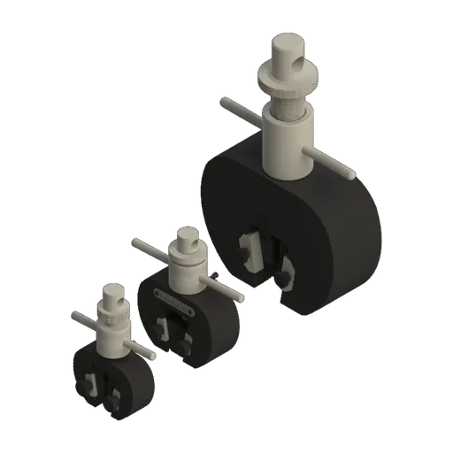
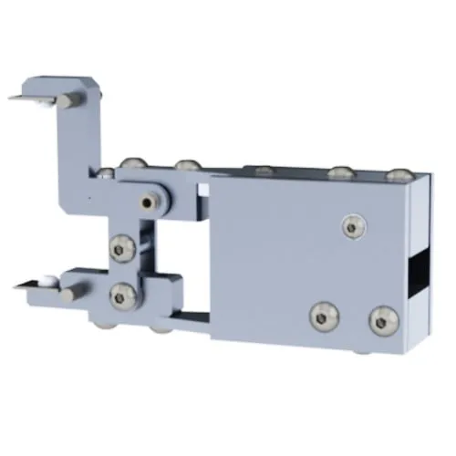
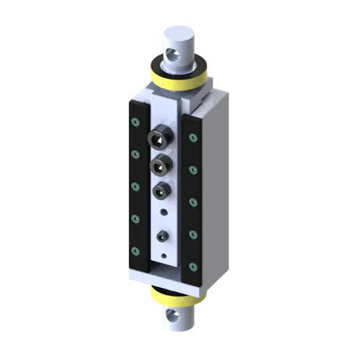
With its range of up to 10 N·m, the torsion testing machine covers wires, small bolts and small-diameter metal and polymer specimens. A 40 mm shaft like the one in Example 4 already works at hundreds of N·m: for higher torques, ask about other capacities or our special projects. The other properties measured on the universal testing machine are covered in mechanical properties of materials, and you can request a quote for the specimens your lab tests.
Shear modulus standards
Test standards specify how to measure G for each class of material; design standards specify which value to use when it is not measured. The table lists the standards cited in this article, with the edition checked on October 1, 2026:
| Standard | Scope | Edition |
|---|---|---|
| ASTM E143 | shear modulus by torsion, at room temperature | E143-20 |
| ASTM E1876 | dynamic E, G and ν by impulse excitation | E1876-22 |
| ASTM D5379/D5379M | shear testing of composites, V-notched beam | D5379/D5379M-19(2026) |
| ASTM D7078/D7078M | shear testing of composites, V-notched rail | D7078/D7078M-20(2025) |
| ASTM D3518/D3518M | in-plane shear of composites by tensile test of a ±45° laminate | D3518/D3518M-18(2025) |
| ASTM C273/C273M | shear modulus and shear strength of sandwich cores | C273/C273M-20 |
| ISO 1827 | shear modulus of rubber and adhesion to rigid plates, quadruple shear | ISO 1827:2022 |
| ASTM D8295 | shear wave velocity and G0 of soils by bender elements | D8295-19 |
| ASTM D4015 | modulus and damping of soils by resonant column | D4015-21 |
| ISO 6721 series | dynamic mechanical properties of plastics (DMA) | not specified |
| ABNT NBR 8800 | Brazilian standard for steel and composite structures: E = 200,000 MPa, G = 77,000 MPa, ν = 0.3 | 2024 (corrected version 2025); values checked against the 2008 edition |
| ABNT NBR 6118 | Brazilian standard for concrete structures: ν = 0.2 and Gc = Ecs/2.4 (item 8.2.9) | 2023, with Amendment 1:2026 |
Other tests and technical references
Tests performed on the Biopdi universal testing machine



















Related technical references
Poisson's ratio: what it is, formula, values for steel, concrete and soil, and how to measure it
Poisson's ratio (ν) is the negative ratio of transverse strain to longitudinal strain in a material under uniaxial load in the elastic range. See the formula, its relationship with E, G and K, the range from −1 to 0.5, the values for steel (0.3 per ABNT NBR 8800, the Brazilian steel structures design standard), concrete (0.2 per ABNT NBR 6118, the Brazilian concrete structures design standard), rubber and soils, how to measure it per ASTM E132, and worked examples.
Torsion test: formulas, shear modulus G, fracture and standards
Torsion test: torque is applied to a cylindrical specimen and twist angle measured. Formulas (τ = T·r/J), shear modulus G, fracture, standards.
Modulus of elasticity (Young's modulus): what it is, formula, units, table of materials and how to measure it
The modulus of elasticity, or Young's modulus (E), is the ratio of stress to strain in the linear elastic region, E = σ/ε, and measures a material's stiffness. See the formula, the units and conversions, a table of E for more than 20 materials, the relationship with G, K and Poisson's ratio, the tangent, secant and chord moduli, and how to measure it with an extensometer.
Frequently asked questions
What is the formula for the shear modulus?
G = τ/γ: the shear stress, in MPa, divided by the shear strain in radians, in the elastic range. For an isotropic material, G = E/[2(1 + ν)] also holds. For steel, with E = 200 GPa and ν = 0.3, G = 76.9 GPa, which NBR 8800 (the Brazilian steel structures design standard) rounds to 77 GPa.
What is the transverse modulus of elasticity?
It is the same shear modulus G (also called the modulus of rigidity), under the name used in Brazilian design standards. It measures the material's stiffness against shear distortion, just as Young's modulus measures stiffness against elongation.
What is shear? Give an example.
Shear is loading by forces parallel to a section, which tend to make one part of the material slide over the other. Examples: scissors cutting paper, the pin of a hinge, the bolt of a connection loaded "sideways," and a twisted shaft, in which each section rotates relative to the next. The test types are covered in the article on shear testing.
What is the shear modulus of steel?
For design, 77,000 MPa (77 GPa) per NBR 8800, with E = 200,000 MPa and ν = 0.3. Measured values range from about 77 to 83 GPa, depending on the alloy: A36 has 79.3 GPa in the MatWeb/ASM data sheet, and Callister lists 83 GPa. Tables giving 80 to 85 GPa start from E between 207 and 210 GPa.
What is the shear modulus of aluminum?
About 25 GPa, the measured value from Callister, with E = 69 GPa and ν = 0.33. From the isotropic formula, 69/2.66 = 25.9 GPa.
What is the relationship between E, G and Poisson's ratio?
G = E/[2(1 + ν)], or ν = E/(2G) − 1, valid only for isotropic, linear elastic materials. Since ν lies between 0 and 0.5 for common materials, G lies between E/3 and E/2.
How do you calculate shear stress?
Divide the force parallel to the section by the area that resists it: τ = F/A, in MPa. In a shaft under torsion, the stress at radius r is τ = T·r/J. The calculation for pins in single and double shear is in the article on shear testing.
What is the unit of shear stress?
Shear stress is measured in pascals (Pa), or N/m², and in practice in MPa, which is the same as N/mm². The modulus G has the same unit, because the shear strain γ is dimensionless, which is why it is written in GPa for metals.
What is the shear strength of 1020 and 1045 steel?
As an estimate, the shear yield strength is about 0.577 times the tensile yield strength (von Mises criterion), and the ultimate shear strength is about 0.6 times the ultimate tensile strength. For hot-rolled SAE 1020 (yield strength 205 MPa, Rm 380 MPa), this gives about 118 MPa and 228 MPa; for hot-rolled SAE 1045 (310 and 565 MPa), about 179 MPa and 339 MPa. These are estimates, not standard values; the actual value is measured in a shear test. The shear modulus G of both steels is the same, about 77 to 80 GPa.
What is the formula for the modulus of elasticity?
E = σ/ε, the slope of the linear portion of the stress-strain curve in a tensile test. If G and ν are known, E = 2G(1 + ν) also applies: a steel with G = 77 GPa and ν = 0.3 has E = 200 GPa.
What is the modulus of elasticity of steel?
For the design of steel structures, 200,000 MPa (200 GPa) per NBR 8800; for concrete reinforcement, 210 GPa per NBR 6118 (the Brazilian concrete structures design standard). Each has its own consistent G: 77 GPa and about 81 GPa, with ν = 0.3. Values by steel type are in the article on the modulus of elasticity of steel.
What is the symbol for the modulus of elasticity?
E for Young's modulus, or longitudinal modulus; G for the transverse modulus of elasticity, or shear modulus; and K for the bulk modulus. ν is Poisson's ratio, which is not a modulus but a ratio between strains.
How is the shear modulus measured?
The classic method is the torsion test per ASTM E143-20: G = (ΔT/Δθ)·L/J, using the slope of the linear portion of the torque vs. angle curve. Other methods are impulse excitation of vibration (ASTM E1876-22), the V-notch tests for composites (ASTM D5379 and D7078) and, for soils, bender elements and the resonant column.
What is the shear modulus of concrete?
Per NBR 6118, Gc = Ecs/2.4, with ν = 0.2, for service stresses. A C30 concrete with granite aggregate has Ecs of 26.8 GPa and Gc of about 11.2 GPa.
What is the modulus of elasticity of 30 MPa concrete?
For a C30 concrete with crushed granite aggregate, NBR 6118 gives an initial tangent modulus Eci = 5,600 × √30 ≈ 30.7 GPa and a secant modulus Ecs ≈ 26.8 GPa. The corresponding shear modulus is Gc = 26.8/2.4 ≈ 11.2 GPa. With a different aggregate, the values change; the full calculation is in the article on the modulus of elasticity of concrete.
What does a low shear modulus mean?
That the material distorts a lot under little stress. This is the case with rubber, with G on the order of megapascals, used in mounts and bearings precisely to let the structure move and to isolate vibration. A low modulus does not mean a weak material, only a flexible one.
Are shear modulus and shear strength the same thing?
No. The modulus is the stiffness, the slope of the τ vs. γ curve, in GPa. The strength is the maximum stress before yielding or fracture, in MPa, measured for example in shear testing of bolts and pins.
Why must the shear strain be in radians?
Because the formula comes from small-angle geometry, in which the angle in radians equals Δx/h. In degrees, the calculated G comes out 57.3 times smaller: a 79 GPa steel becomes 1.38 GPa.