
ASTM D3039/D3039M is the ASTM International test method for measuring the tensile strength, the chord modulus between 1,000 and 3,000 µε, the ultimate strain and Poisson's ratio of polymer matrix composites (PMC) reinforced with high-modulus fibers, tested as a rectangular strip with tabs at 2 mm/min. The current edition is D3039/D3039M-17(2025), reapproved in 2025 with no technical changes. The official title is Standard Test Method for Tensile Properties of Polymer Matrix Composite Materials. The strip has a constant rectangular cross section, with tabs (also called end tabs) bonded to the ends, and the test yields the ultimate tensile strength, Ftu = Pmax / A, the ultimate strain, the chord modulus of elasticity, Poisson's ratio and the transition strain.
In short:
- Scope: continuous or discontinuous fiber laminates that are balanced and symmetric with respect to the test direction: 0° and 90° unidirectional, cross-ply laminates, fabrics and mats.
- Test specimen: a straight strip, without the dog-bone shape used for plastics. Recommended at 0°: 250 × 15 × 1.0 mm with 56 mm tabs.
- Modulus: chord modulus, Δσ between 1,000 and 3,000 µε divided by 0.002, measured with an extensometer or strain gauge, never with the crosshead displacement.
- Validity: the failure mode is recorded with a three-letter code, and repeated failures next to the tab point to a gripping problem, not to the strength of the material.
- It is not ISO 527-4 or ISO 527-5: the specimens and the modulus strain range differ, and the numbers from the two families are not interchangeable.
The standard is a paid document sold by ASTM. This guide explains it in our own words, for the laboratory that will apply it and for those who will buy the equipment, with the essential numerical requirements and the source of each one.
What ASTM D3039 covers and which edition is current
The tensile test of composites is a destructive mechanical test that measures the strength and stiffness of a fiber and resin laminate, such as carbon fiber reinforced polymer (CFRP) or glass fiber reinforced polymer (GFRP). Like every tensile test, it applies an increasing axial force to the test specimen, at a controlled rate, until fracture, and records force and strain. D3039 adapts this test to a material that behaves neither like a metal nor like a plastic: a long-fiber composite is very stiff and strong along the fibers, weak in the transverse direction, fails in a brittle manner and is sensitive to any stress concentration introduced by the grip. Almost every requirement in the standard stems from these four characteristics.
According to the official page of the standard, checked on October 1, 2026 at store.astm.org, the current designation is D3039/D3039M-17(2025), active, 13 pages long, under the responsibility of ASTM subcommittee D30.04. The number in parentheses indicates the 2025 reapproval of the 2017 text. The dual designation means the standard gives values in SI units and in inch-pound units, as two independent systems: the test report uses one of them, without mixing.
The scope is bounded by three conditions:
- Polymer matrix, thermoset (epoxy, polyester, vinyl ester) or thermoplastic.
- High-modulus fiber, such as carbon, glass and aramid, continuous or discontinuous.
- Balanced and symmetric laminate with respect to the test direction. Balanced means that for every ply at +θ there is one at −θ; symmetric, that the ply sequence is mirrored about the midplane. A laminate without these properties twists or bends when pulled, and the strip is no longer in pure tension.
Materials that have their own standard are excluded. Unreinforced plastics, or plastics reinforced with short fibers and injection molded, follow ASTM D638, with a dog-bone specimen. Vulcanized rubber and thermoplastic elastomers follow ASTM D412. Metals follow ASTM E8/E8M or ISO 6892-1, covered in the guide ASTM E8 and ISO 6892-1. Within the composites family itself, in-plane shear strength measured on a ±45° laminate follows ASTM D3518/D3518M, and compression, flexure and interlaminar shear have sister standards, listed at the end of this guide.
The test specimen: rectangular strip with tabs
The D3039 test specimen is a flat strip, of constant width and thickness along its whole length, cut from a laminated plate. The ends, which go into the grips, usually receive tabs (end tabs): bonded plates that protect the laminate from the clamping pressure and distribute the force. In the middle is the gauge section, where the extensometer or strain gauge is installed and where fracture should occur. The general idea of a test specimen, with the shapes used for other materials, is covered in the article test specimen.
Why the strip is straight, without a dog-bone shape
In metals and plastics, the test specimen has a reduced central section so that fracture occurs away from the grip. In a continuous fiber composite, the reduced section would be machined across the fibers. Every fiber cut at the fillet loses continuity with the specimen head, and the force it carried must pass to the neighboring fibers through shear in the matrix, which is much weaker. Stress concentrates precisely at the fillet radius, and fracture starts there, through a mechanism that does not exist in the real part. The straight strip keeps the fibers intact from one grip to the other; the price is that load introduction is left to the tabs, and their quality then decides whether the test is valid.
Recommended dimensions by orientation
The standard does not have a single size. It sets general requirements for the test specimen and recommends geometries by laminate type, because the width, thickness and tab that work well depend on the fiber orientation. The diagram below shows the three recommended geometries at the same length and width scale, with the thickness enlarged in the side view: the 0° specimen is long and narrow, with beveled tabs; the 90° specimen is shorter and wider, with straight tabs; the balanced laminate needs no bonded tab.
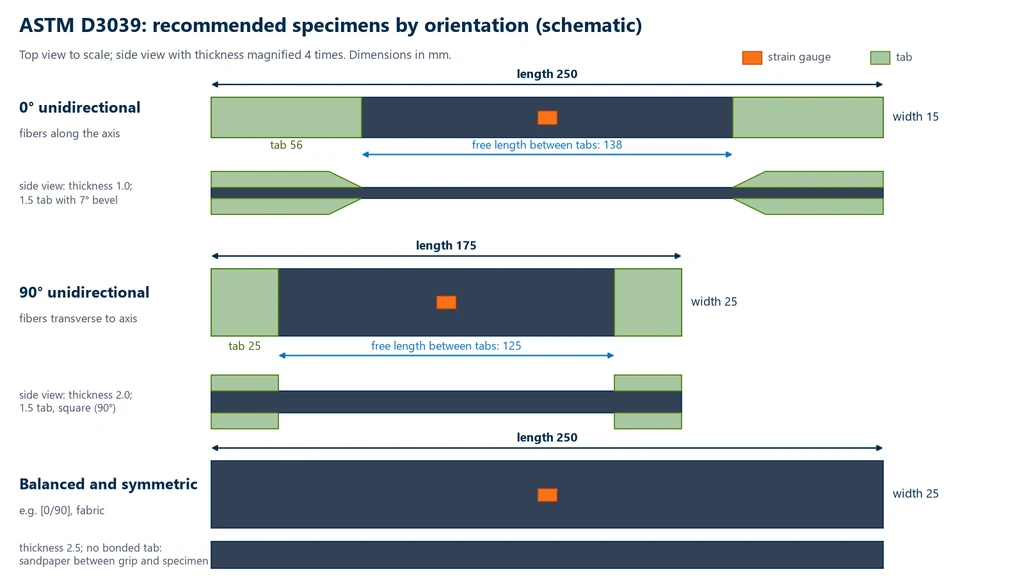
The table summarizes the recommended geometries, in millimeters. At 0°, the 56 mm tabs leave 250 − 2 × 56 = 138 mm of free length; at 90°, 175 − 2 × 25 = 125 mm remain:
| Laminate | Width × length × thickness | Tab (length × thickness, bevel) |
|---|---|---|
| 0° unidirectional | 15 × 250 × 1.0 | 56 × 1.5, 7° bevel or straight |
| 90° unidirectional | 25 × 175 × 2.0 | 25 × 1.5, straight (90°) |
| Balanced and symmetric | 25 × 250 × 2.5 | no bonded tab; abrasive paper in the grip |
| Random discontinuous | 25 × 250 × 2.5 | no bonded tab; abrasive paper in the grip |
Sources: table of recommended geometries in D3039/D3039M (checked in the 2014 edition, retained in 2017) and the Grasse Zur laboratory, which applies the standard.
Tabs: material, bevel and bonding
The most common tab is a glass/epoxy laminate plate with the fibers at ±45°, bonded with a structural adhesive. Glass at ±45° has low stiffness in the load direction, so the tab follows the deformation of the test specimen instead of restraining it, and it withstands the grip serrations well. The standard accepts bevel angles from 5° to 90°, but notes that, with wedge grips, the best results come from shallow bevels, of 7° to 10°: the tab thickness increases gradually and the force passes into the laminate along a ramp, without a step. With non-wedge pressure grips, a straight tab works. The tabs on the same test specimen must have the same thickness, because any difference offsets the load axis from the laminate axis and introduces bending.
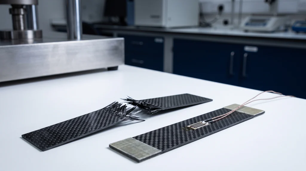
There are two alternatives to the bonded tab. The friction tab is not bonded: it is held only by the grip pressure, with abrasive paper between it and the test specimen. And on a balanced laminate, which is less sensitive to clamping, the tab can be omitted and a folded strip of 80 to 150 grit abrasive paper, with the abrasive side facing the specimen, placed between the specimen and the serrations. In the photo, two carbon fiber test specimens with tabs bonded at the ends: one failed in the gauge section, with splintered fibers, and the other still has the strain gauge at the center, which measures the strain for the modulus.
Cutting, measurement and number of test specimens
The strip is cut from the plate with a cooled diamond blade or by milling, so that the edges are smooth and parallel. A rough cut leaves microcracks and pulled-out fibers on the edge, and that is where edge delamination starts. On 0° unidirectional material, the cut must also follow the fiber direction: a deviation of a few degrees makes some fibers end at the free edge, and the measured strength drops. Laboratories that run the test frequently, such as Element, keep the alignment between cut and fiber within 0.5°. The standard allows a variation of ±1 % in width and ±4 % in thickness along the test specimen and requires it to be flat. Width and thickness are measured in the gauge section; on an irregular surface, such as the face of a fabric, the thickness is read with a ball-point micrometer, which does not rest only on the peaks of the weave. The area A = width × thickness, using the average values, is the one used in all calculations.
The minimum is five test specimens per test condition, unless a valid sampling plan justifies another number. A test condition is each combination of material, orientation, temperature and humidity. When the contract calls for testing in the wet condition, conditioning follows ASTM D5229/D5229M. Cold or hot tests, common in aerospace qualification, require a thermal chamber mounted between the grips and a strain transducer that works at the test temperature; the test report records the temperature and the soak time of the test specimen.
What each orientation measures: 0°, 90° and [0/90]
The same plate gives very different results depending on the direction in which the strip is cut, and each orientation answers a different question about the material:
- 0° unidirectional: the force runs along the fibers, and the fiber carries the load. The result is the longitudinal strength and modulus of the material, the highest possible. In an aerospace carbon/epoxy, the strength exceeds 2,000 MPa and the modulus is around 160 GPa, with a practically straight curve up to fracture, without yielding.
- 90° unidirectional: the force is transverse to the fibers, and the matrix and the fiber-matrix interface carry the load. The strength drops to tens of MPa, the modulus to a few GPa, and the strain at fracture is usually below 1 %. This is the property that governs matrix cracking in the laminate.
- [0/90] laminate and fabric: the force is shared between the 0° plies, which carry most of it, and the 90° plies. At some point on the curve, the 90° plies crack; the laminate stiffness drops at once and the curve changes slope, forming a "knee". The strain at which this occurs is the transition strain, which D3039 requires to be reported when it exists.
That is why the test report always identifies the laminate by its ply sequence and the test direction. "Tensile strength of the composite" without an orientation has no meaning. The relationship between the stiffnesses in the two directions also appears in Poisson's ratio, which in a composite depends on the direction in which it is measured, as explained in the article Poisson's ratio.
Machine, grips, alignment and speed
The test is performed on a universal testing machine with one fixed head and one moving head. The standard requires the force to be verified per ASTM E4, with an error within ±1 % of the indicated value over the range of use. In Brazil, the equivalent verification is per ABNT NBR ISO 7500-1:2023 (the Brazilian adoption of ISO 7500-1), whose class 1 corresponds to the same ±1 %. The class applies within the verified range stated on the certificate, and D3039 draws attention to a conflict specific to this test: the modulus is calculated with small forces, at the beginning of the curve, and the strength with the maximum force. The load cell must be accurate at both ends, which sometimes calls for an extended calibration or different ranges. How the load cell works is covered in load cell.
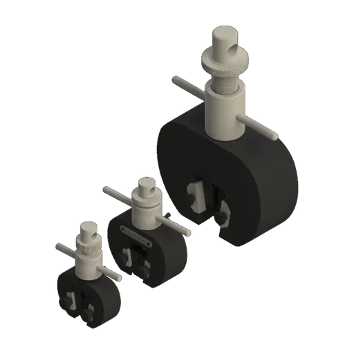
The grips must hold the test specimen without letting it slip and without marking it. The most common are wedge grips, mechanical, pneumatic or hydraulic. In a wedge grip, the clamping force increases with the tensile force; the standard recommends fine serrations, around one tooth per millimeter, because coarse serrations bite into the laminate and cause failure in the grip on specimens without tabs. The pneumatic wedge grip adds a controlled initial clamping force that is repeated from one test specimen to the next, which helps reproducibility.
Alignment is the requirement that weighs most on the result. If the grip axis does not coincide with the specimen axis, the strip is subjected to tension and bending at the same time: one face strains more than the other, the calculated modulus varies from one test specimen to another and fracture comes early. The standard calls for grips that align the load axis with the specimen axis, preferably self-aligning, and recommends evaluating the system with a test specimen instrumented with strain gauges on its faces, per ASTM E1012. As good practice, system bending stays between 3 % and 5 % at strains above 1,000 µε.
The speed must produce a nearly constant strain rate in the gauge section, chosen so that fracture occurs between 1 and 10 minutes. When the ultimate strain of the material is not known, the standard suggests default speeds for the first tests: 0.01 min⁻¹ in strain control or 2 mm/min of crosshead displacement. Once the material and the system stiffness are known, the speed is adjusted to fall within the window.
Strain, chord modulus and Poisson's ratio
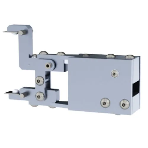
Strain is measured in the gage section with an extensometer or a bonded strain gauge, placed at mid-length and mid-width. The extensometer is removable and can be reused on many specimens; the strain gauge is bonded to each one, measures a single point with high resolution and is lost at fracture. The differences between the two, and when to use each, are covered in the article extensometer and strain gauge. With carbon fiber, which fractures violently, the contact extensometer is often removed before the end of the test or replaced by non-contact measurement.
The chord modulus is the slope of the straight line connecting two fixed points on the stress-strain curve: 1,000 µε and 3,000 µε. The calculation is Echord = (σ3000 − σ1000) / (0.003 − 0.001) = Δσ / 0.002. This range should fall in the lower half of the curve. For materials that fail at less than 6,000 µε, such as most 90° laminates, the range becomes 25% to 50% of the ultimate strain. If the curve changes slope within the range, another range is chosen, and the test report states which one was used. The concept of modulus, also called Young's modulus, is explained in modulus of elasticity.
Poisson's ratio requires a second measurement, transverse strain, taken with a biaxial strain gauge, a 0°/90° rosette or a biaxial extensometer. It is calculated over the same range as the modulus, using the changes in the two strains: ν = −Δεt / Δεl. The negative sign is there because the transverse strain is a contraction.
Specimen bending is measured with two transducers on opposite faces, read at the 2,000 µε point: By = (εf − εv) / (εf + εv) × 100, where εf is the front-face strain and εv the back-face strain. The standard requires this check on at least one specimen per sample. If bending is 3% or less, the remaining specimens may be tested with a single transducer; above that, the average of the two faces is used. The table summarizes the formulas:
| Result | Formula | Note |
|---|---|---|
| Ultimate tensile strength | Ftu = Pmax / A | maximum force before failure, in MPa |
| Stress at each point | σi = Pi / A | A = average width × thickness |
| Strain | εi = δi / Lg | 1,000 µε = 0.001 |
| Chord modulus | Echord = Δσ / Δε | from 1,000 to 3,000 µε, or 25% to 50% of ultimate |
| Poisson's ratio | ν = −Δεt / Δεl | same range as the modulus |
| Specimen bending | By = (εf − εv) / (εf + εv) × 100 | at the 2,000 µε point |
Strength and modulus are reported to three significant figures, and the modulus always with the strain range used. Ultimate tensile strength is the same concept explained in ultimate tensile strength, applied to a material that fails without yielding.
Failure modes: the three-letter code
In a composite, the strength value only counts if the fracture happened in the right way and in the right place. That is why D3039 requires the failure mode of each specimen to be recorded with a three-letter code, which works like an address: the first letter says how it failed (the type), the second says where along the length (the area), and the third says at which end or side (the location). The diagram below shows the most common letters for each position and, on an upright specimen, the areas of the second letter and four marked examples: two that are accepted and two that call for investigation.
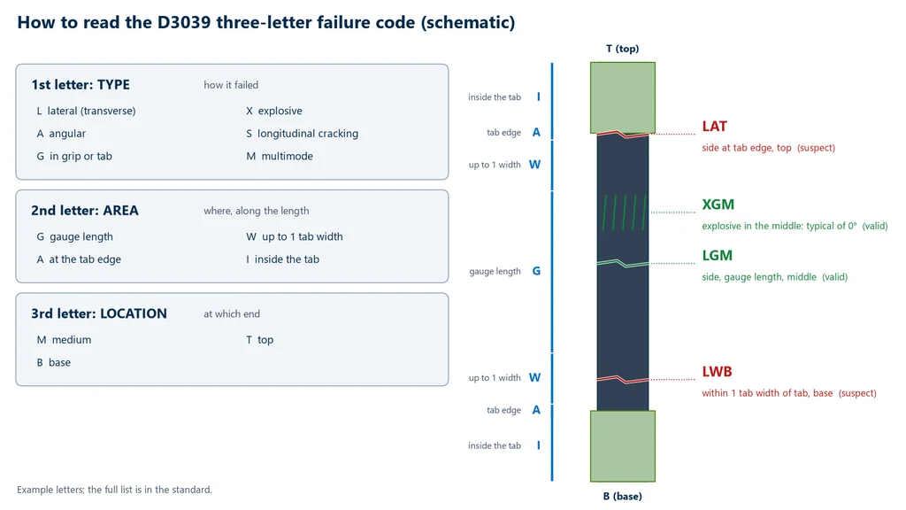
Read logically, the codes can be interpreted without a table:
- LGM: lateral fracture (transverse to the axis), in the gage section, in the middle. This is the reference failure, valid.
- XGM: explosive fracture, in the gage section, in the middle. It is typical of 0° carbon, which releases the stored elastic energy all at once and breaks up into fiber bundles, as in the previous photo. It is accepted.
- LAT: lateral fracture right at the tab edge, at the top. The tab concentrated stress; the value tends to fall below the true strength.
- LWB: lateral fracture less than one width from the tab, at the bottom. It is still in the zone disturbed by the load introduction, and is suspect for the same reason.
- Codes with G as the first letter, or I as the second: the failure occurred in the grip or inside the tab, including tab debonding. They do not measure the laminate.
The standard does not automatically discard every failure near the tab. The criterion is statistical: if a significant fraction of the failures in a sample occur within one width of the tab or grip, the load introduction method must be re-examined (tab material and bevel, adhesive, grip pressure and serrations, alignment) before continuing. Because these failures lower the average in proportion to the tab's stress concentration, laboratory practice is not to use them as the material strength and to report them separately.
How the ASTM D3039 tensile test is performed, step by step
The ASTM D3039 tensile test is a sequence of preparation, gripping, loading to fracture and calculation, in which each step controls a source of error described in the previous sections. At the bench, the order is as follows:
- Identify and cut: define the laminate, the ply stacking sequence and the test direction; cut the strips from the panel with a water-cooled diamond blade or by milling, aligned with the fibers.
- Bond the tabs: bond tabs of equal thickness at both ends, cure the adhesive and number each specimen.
- Condition and measure: condition when the test plan requires it (ASTM D5229/D5229M for moisture) and measure width and thickness at several points in the gage section to obtain the average area A.
- Instrument: bond the strain gauge or mount the extensometer at the center of the gage section; for Poisson's ratio, use a biaxial transducer or a 0°/90° rosette.
- Grip: clamp the tabs in the grips with the strip axis aligned with the load axis and zero the force before loading.
- Test: pull at 2 mm/min, or at the speed adjusted to cause fracture within 1 to 10 minutes, recording force and strain up to fracture.
- Classify the failure: record the three-letter code for each specimen and set aside failures near the tab or in the grip.
- Calculate and repeat: calculate Ftu, the chord modulus, Poisson's ratio and the transition strain, and repeat until there are at least five valid results per condition.
What the test report must contain
The report of a D3039 tensile test is the document that allows the test to be repeated and the result to be compared with another laboratory; that is why it records, besides the numbers, everything that influences them. The items below follow the logic of the standard's report section, in our own words:
- Standard and edition: ASTM D3039/D3039M-17(2025) and any deviation from the method.
- Material: fiber, matrix, manufacturer, batch, cure process, stacking sequence and, when measured, fiber and void content (ASTM D3171).
- Specimen: geometry, average width and thickness of each one, cutting method, tab material, thickness and bevel, and adhesive.
- Test conditions: conditioning, test temperature and humidity, machine, grips, strain transducer, gage length and speed.
- Results per specimen: maximum force, Ftu, ultimate strain, chord modulus with the range used, Poisson's ratio, transition strain when present, and failure code.
- Sample statistics: number of specimens, mean, standard deviation and coefficient of variation of each property.
The BioLab software builds the numerical part of this report from the recorded curve; the material, cutting and tab data come from the laboratory's preparation record.
How to interpret the standard
D3039 is written as a method, with several decisions left to the laboratory and justified only by the result. The points below are the ones most often misread at the bench and in specifications, with the reason for each.
Are the recommended dimensions mandatory?
No. The standard separates requirements from recommendations. Mandatory are the constant rectangular cross section, the width and thickness tolerances, flatness and a minimum length sufficient for the grips, the gage section and keeping fracture away from the grips, which the standard expresses as the gripping length plus twice the width plus the gage length. The geometries in the table, such as 15 × 250 × 1.0 mm at 0°, are recommended because they tend to produce acceptable failures. A laboratory may use another geometry within the requirements, as long as it reports it. The practical consequence is that two D3039 test reports with different geometries are not, strictly speaking, comparable, especially for strength, which depends on the volume of material stressed.
Can the test be run without tabs?
Yes, and the standard says so explicitly: if the gripping system produces acceptable failures at a reasonable rate, there is no reason to change it. Tabs are strongly recommended for 0° unidirectional material, where the force is high and the thin laminate cannot withstand the bite of the serrations, and may be needed at 90°, where the laminate is brittle and cracks in the grip. For balanced laminates and random-fiber composites, emery cloth in the grip is usually enough. The result decides: if failures migrate to the grip or to the tab edge, tabs come back or are changed.
Why does the modulus start at 1,000 µε and not at zero?
The beginning of the curve mixes the material response with the seating of the specimen in the grips, the settling of the extensometer and the straightening of small curvatures in the strip. By 1,000 µε these effects are over, and up to 3,000 µε most composites are still far from any damage. A chord between two fixed points also makes the value reproducible: two laboratories calculate the same value over the same points, regardless of who picked the "linear portion". The 6,000 µε rule follows the same logic. In a material that fails at 5,000 µε, the standard range would extend to 60% of fracture, already in the region where the matrix begins to crack; the 25% to 50% range brings the measurement back to the initial portion.
Is a single transducer enough?
Yes, once it has been shown that bending is small. The strip is thin, and a misalignment of tenths of a millimeter makes one face strain more than the other. A transducer on one face reads that strain as if it belonged to the whole material and errs on the modulus, high or low depending on the face. That is why the standard requires transducers on both faces on at least one specimen per sample: if bending at the 2,000 µε point is 3% or less, the system is well aligned and one transducer represents the average; above that, the average of the two faces is mandatory, and the alignment must be corrected.
What does "balanced and symmetric" mean in practice?
It means the laminate has no coupling. In an unbalanced laminate, tension produces shear distortion and the strip tends to twist; in an unsymmetric laminate, tension produces curvature and the strip tends to bend. Clamped in the grips, it is prevented from twisting or bending, and the stresses that arise do not appear in the P / A calculation. A result comes out, but it does not measure the property its name suggests. Laminates with off-axis plies also have an edge effect: interlaminar stresses concentrate at the free edge of the strip and can greatly underestimate strength and stiffness, a limitation the standard itself notes.
Is the D3039 result valid as a design value?
Not on its own. D3039 gives the strength and modulus of one sample under one test condition. Design values require several material batches, environmental conditions (cold, hot, wet) and statistical treatment specific to each industry, such as aerospace. The standard is the building block of that structure, which is why the test report must record everything that defines the test, with the items listed in the section on the report.
Worked examples
The examples use hypothetical numbers that are consistent with real materials, and they follow the order of work in the lab: stress, modulus, Poisson's ratio, bending, choice of strain range and validity of the failures. In every case, the area is the average measured in the gage section.
Example 1: unidirectional carbon/epoxy at 0°
A 0° test specimen with an average width of 15.00 mm, an average thickness of 1.00 mm and 56 mm glass/epoxy tabs fails at 36.0 kN, with an XGM failure. The strain gauge recorded 2.42 kN at 1,000 µε and 7.26 kN at 3,000 µε. Calculate the strength and the modulus, and choose the machine.
- Area: A = 15.00 × 1.00 = 15.0 mm².
- Strength: Ftu = 36,000 / 15.0 = 2,400 MPa. The XGM failure is in the gage section, so the value is valid.
- Chord stresses: σ1000 = 2,420 / 15.0 = 161.3 MPa; σ3000 = 7,260 / 15.0 = 484.0 MPa.
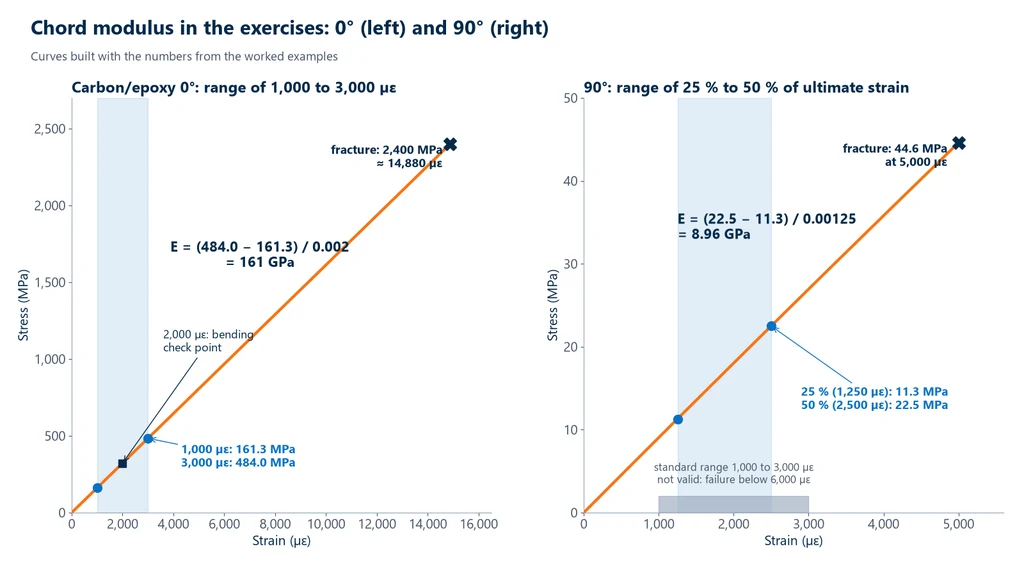
- Modulus: Echord = (484.0 − 161.3) / 0.002 = 322.7 / 0.002 = 161,350 MPa, reported as 161 GPa (range of 1,000 to 3,000 µε).
- Check: since the curve of carbon at 0° is practically a straight line, the ultimate strain is close to 2,400 / 161,350 = 0.0149, or about 14,900 µε. The modulus range ends at 3,000 µε, well within the lower half of the curve, as the standard requires. Both modulus and strength fall within the published range for intermediate-modulus carbon with epoxy, around 160 GPa.
- Test time: at 2 mm/min over a 138 mm free length between the tabs, the nominal strain rate is 2 / 138 = 0.0145 min⁻¹, and failure would occur at 0.0149 / 0.0145 ≈ 1.0 min. Because part of the crosshead displacement is lost in the grips and the tabs, the actual strain rate is lower and the test takes a little longer, within the 1 to 10 minute window.
- Machine: 36 kN requires the 50 kN dual-column machine, with wedge grips or pneumatic wedge grips of that capacity; the 20 kN grip is not enough. Note that the modulus force, 2.42 kN, is less than 5% of the capacity: the calibration certificate of the load cell must cover this range.
Example 2: Poisson's ratio and bending
On the same test specimen, the transverse strain gauge read −310 µε when the longitudinal gauge showed 1,000 µε, and −930 µε at 3,000 µε. On a sister specimen with gauges on both faces, the reading at the 2,000 µε point was 2,080 µε on the front and 1,920 µε on the back.
- Poisson's ratio: Δεt = −930 − (−310) = −620 µε; Δεl = 3,000 − 1,000 = 2,000 µε. ν = −(−620) / 2,000 = 0.31, a typical ν12 value for unidirectional carbon/epoxy.
- Bending: By = (2,080 − 1,920) / (2,080 + 1,920) × 100 = 160 / 4,000 × 100 = 4%.
- Decision: since this exceeds 3%, the sample cannot be tested with a single transducer. The average of the two faces, 2,000 µε, is used, and the grip alignment and tab thickness are checked before the next specimens. A single gauge on the front would have read 4% more strain at that point, and the modulus calculated from it would come out proportionally lower.
Example 3: unidirectional at 90°, failing below 6,000 µε
A 90° specimen of the same material, with a 25.0 × 2.00 mm cross-section, fails at 2.23 kN, with an LGM failure, at 5,000 µε. The forces read were 0.565 kN at 1,250 µε and 1.125 kN at 2,500 µε.
- Area and strength: A = 25.0 × 2.00 = 50.0 mm²; Ftu = 2,230 / 50.0 = 44.6 MPa.
- Choice of range: failure, at 5,000 µε, occurred below 6,000 µε, so the standard range does not apply. The new range goes from 25% to 50% of the ultimate strain: 0.25 × 5,000 = 1,250 µε and 0.50 × 5,000 = 2,500 µε.
- Stresses: σ = 565 / 50.0 = 11.3 MPa and σ = 1,125 / 50.0 = 22.5 MPa.
- Modulus: E = (22.5 − 11.3) / (0.0025 − 0.00125) = 11.2 / 0.00125 = 8,960 MPa, reported as 8.96 GPa (range of 1,250 to 2,500 µε).
- Consistency: if the curve were straight to the end, 8.96 GPa at 5,000 µε would give 44.8 MPa; failure at 44.6 MPa shows a curve that softens only very slightly at the end, as expected for a matrix-dominated property.
- Speed: at 2 mm/min over a 125 mm free length, the nominal strain rate would be 0.016 min⁻¹ and failure would occur at 0.005 / 0.016 ≈ 0.31 min, under 1 minute. At 0.5 mm/min, the nominal strain rate drops to 0.004 min⁻¹ and the test lasts about 1.25 min or longer, within the window.
- Machine: 2.23 kN fits a 5 or 10 kN single-column machine, with a 5 kN wedge grip.
The charts below show Examples 1 and 3 as the software plots them: on the left, the straight line of the 0° specimen up to 2,400 MPa, with the 1,000 to 3,000 µε range shaded and the bending check point at 2,000 µε; on the right, the 90° curve, where the standard range (gray, at the bottom) gives way to the range of 25% to 50% of the ultimate strain.
Example 4: a batch with grip failures
A sample of six 0° specimens fails with the codes XGM, LGM, LGM, LAT, XGM and LWB. How many results represent the material, and what should be done?
- Classification: XGM, LGM, LGM and XGM failed in the gage section, at the middle: these are four representative results.
- Suspect failures: LAT (at the tab edge, top) and LWB (less than one width from the tab, bottom) are in the load introduction zone. That is 2 out of 6, one third of the sample, a significant fraction by the standard's criterion.
- Decision: before testing more, re-examine load introduction: tab thickness and bonding, bevel, grip pressure and serrations, alignment. With four valid results, the sample is below the minimum of five per condition; after the correction, new specimens are tested until the number is reached, and the report records all six codes.
ASTM D3039, ISO 527-4 and ISO 527-5
ISO 527-4 and ISO 527-5 are the international standards equivalent to D3039 for tensile testing of fiber-reinforced plastics. Outside the United States, the same test is often specified by ISO 527, which splits composites into two parts. According to iso.org, checked on October 1, 2026, ISO 527-4:2023 (3rd edition, published in March 2023) covers isotropic and orthotropic composites, such as mats, fabrics and symmetric multidirectional laminates, and ISO 527-5:2021 (3rd edition, November 2021) covers unidirectional composites. Both rely on the general principles of ISO 527-1. D3039 brings both cases together in a single method. The table compares the points that change the result the most:
| Item | ASTM D3039/D3039M-17(2025) | ISO 527-4:2023 | ISO 527-5:2021 |
|---|---|---|---|
| Materials | all balanced and symmetric | mats, fabrics, multidirectional | unidirectional |
| Test specimen | rectangular strip, optional tabs | dog-bone or rectangular strip, with or without tabs | tabbed strip: 15 × 1 mm at 0°, 25 × 2 mm at 90° |
| Tab | beveled (5° to 90°) or straight | straight | straight |
| Modulus range | 1,000 to 3,000 µε | 0.05% to 0.25% (500 to 2,500 µε) | 0.05% to 0.25% |
Sources: store.astm.org and iso.org (scope and editions); ZwickRoell (ISO specimens and tabs). The recommended cross-sections at 0° and 90° are the same in both families, but the modulus range and the tab shape are not. For 0° carbon with a straight curve, the difference in modulus is small; for a laminate whose initial portion already curves, the two ranges give different numbers. A data sheet produced to ISO cannot be compared with a specification written to ASTM without testing to the required standard, and the report cites the standard and edition used.
Common mistakes when applying ASTM D3039
The mistakes below show up both in the lab and on pages that explain the standard, and each one has a straightforward fix:
- Using the D638 dog-bone specimen for a continuous-fiber composite. The reduced section cuts fibers and failure starts at the fillet. The straight strip is the D3039 geometry.
- Calculating the modulus from crosshead displacement. The displacement includes seating, deformation of the tabs and adhesive and grip slack, and gives a modulus that is far too low. The standard requires an extensometer or strain gauge.
- Counting failures at the grip or the tab edge as material strength. They lower the average and hide a gripping problem.
- Tabs of different thicknesses, poorly bonded or misaligned. They cause bending and debond; the failure code then has G as the first letter or I and A as the second.
- Not measuring bending. A gauge on one face only, in a misaligned system, gives the wrong modulus with no sign of it in the curve.
- Using the 1,000 to 3,000 µε range for a 90° laminate or for a curve with a knee inside the range. The standard requires changing the range and reporting the one chosen.
- Testing at 2 mm/min without checking the time to failure. At 90°, failure comes within seconds; the standard speed is a starting point, not a rule.
- Rough cutting. Microcracks at the edge initiate delamination and reduce strength, especially in multidirectional laminates.
- Testing an unbalanced or asymmetric laminate to D3039 and reporting the result as a material property.
- Citing the D3039-08 edition, which still appears in automated search summaries, or working from an unauthorized PDF of an old edition. The current edition is D3039/D3039M-17(2025).
Equipment for testing to ASTM D3039
The test requires a universal testing machine with a low, stable crosshead speed, covering fractions of a millimeter per minute up to the standard 2 mm/min, a load cell with good accuracy both at the modulus forces and at the failure force, aligned wedge grips and a small-strain extensometer on the gage section. In Biopdi's M2 line, the dual-column MBIOII-50-M2 is offered from 5 to 50 kN, with speeds from 0.02 to 500 mm/min, and lists composites among its applications. The load cell is class 1 per ISO 7500-1:2023 (ABNT NBR ISO 7500-1 in Brazil), and the BioLab software records the curve and generates the report. The panel below shows the machine, the role of each part in testing to D3039 and the fixtures used.
The universal testing machine in composite tensile testing
The M2 line has single-column models, from 200 N to 10 kN, suited to 90° specimens, and dual-column models, from 5 kN to 1,000 kN, for 0° and balanced laminates. In testing to D3039, each part of the machine has a function:

- Moving crosshead pulls the strip at 2 mm/min or less
- Load cell measures from the modulus forces to failure, class 1
- Wedge grips clamp the tabs aligned with the strip axis
- Extensometer of 25 or 50 mm on the gage section
- BioLab software records the curve and generates the report
- Control panel and emergency stop position and stop the test
Fixtures for composite tensile testing
The grips and extensometer below are mounted on the same machine, depending on the specimen force:

Model selection starts from the maximum expected force, F ≈ Ftu × A. The table below indicates the model by specimen type, with typical forces calculated from the worked examples:
| Test specimen | Typical force | Biopdi model |
|---|---|---|
| 90° unidirectional, 25 × 2 mm | a few kN (2.2 kN in Example 3) | MBIOI-10-M2 (2, 5 or 10 kN) |
| 0° unidirectional carbon, 15 × 1 mm | 30 to 45 kN (36 kN in Example 1) | MBIOII-50-M2 (5 to 50 kN) |
| Thicker or wider laminates | above 50 kN | MBIOII-200-M2 (100 to 200 kN) |
A 25 × 2.5 mm balanced laminate, with a 62.5 mm² cross-section, fails at 50 kN if its strength is 800 MPa: it sits at the limit of the 50 kN machine, and the margin decides between it and the 200 kN machine. The same machine performs flexural testing of composites, covered in the article flexural test, and compression testing, covered in compression test. How the machine works internally is explained in universal testing machine, and for a proposal configured for your lab, request a quote.
Standards cited
The table lists the standards cited in this guide, with the current edition checked on October 1, 2026 on each organization's official website:
| Standard | Subject | Edition |
|---|---|---|
| ASTM D3039/D3039M | tensile testing of polymer matrix composites | 17 (reapproved 2025) |
| ISO 527-4 | tensile testing of isotropic and orthotropic composites | 2023 |
| ISO 527-5 | tensile testing of unidirectional composites | 2021 |
| ISO 527-1 | tensile testing of plastics: general principles | 2019 |
| ASTM D3518/D3518M | in-plane shear by ±45° tensile test | 18 (reapproved 2025) |
| ASTM D3410/D3410M and D6641/D6641M | compression testing of composites | 16 (reapproved 2024) and 23 |
| ASTM D7264/D7264M | flexural testing of composites | 26 |
| ASTM D2344/D2344M | short-beam interlaminar shear strength | 22 |
| ASTM D5766/D5766M | open-hole tensile strength | 23 |
| ASTM D5229/D5229M | moisture absorption and conditioning | 20 |
| ASTM D3171 | fiber and void content | 22 |
| ASTM E4 | force verification of testing machines | 24 |
| ASTM E1012 | alignment verification | 19 |
| ASTM D638 | tensile testing of plastics | 22 |
| ASTM D412 | tensile testing of rubber and thermoplastic elastomers | 16 (reapproved 2021) |
| ASTM D882 | tensile testing of thin plastic sheeting (films) | 26 |
| ASTM E8/E8M | tensile testing of metals | 25 |
| ABNT NBR ISO 6892-1 | tensile testing of metallic materials at room temperature (Brazilian adoption of ISO 6892-1) | 2024 |
| ABNT NBR ISO 7500-1 | force verification of testing machines (Brazilian adoption of ISO 7500-1) | 2023 |
Other tests and technical references
Tests performed on the Biopdi universal testing machine



















Related technical references
ASTM D638: tensile testing of plastics, Type I to V specimens, test speed and calculations
ASTM D638-22 is the ASTM method for the tensile properties of plastics up to 14 mm thick, using Type I to V dumbbell specimens. See dimensions, test speed, conditioning, extensometer, formulas, a worked example and the differences from ISO 527-2:2025.
ASTM D882: tensile testing of plastic films, strip specimen, test speed and secant modulus
ASTM D882-26 covers tensile testing of plastic films under 1.0 mm thick in 5 to 25.4 mm strips: speed, grips, secant modulus, example and D638 differences.
ASTM E8 vs ISO 6892-1: tensile testing of metals, differences and requirements (NBR ISO 6892-1 and A370)
ASTM E8/E8M-25 and ISO 6892-1:2019, adopted in Brazil as ABNT NBR ISO 6892-1:2024, cover the same tensile test of metals at room temperature. They differ in the specimen gauge length (4D in E8, 5D in E8M and 5.65√S0 in ISO), in speed control and its tolerance, in symbols, in rounding and in the standards for the machine and the extensometer. For that reason, elongation from one cannot be compared directly with elongation from the other.
Frequently asked questions
What is ASTM D3039?
It is the ASTM International test method for determining the in-plane tensile properties of polymer matrix composites reinforced by high-modulus fibers: ultimate tensile strength, ultimate strain, chord modulus, Poisson's ratio and transition strain. The current edition is D3039/D3039M-17(2025).
What is the standard specimen size for ASTM D3039?
There is no single size. The recommended geometries are 15 × 250 × 1.0 mm for 0° unidirectional, with 56 mm tabs; 25 × 175 × 2.0 mm for 90° unidirectional, with 25 mm tabs; and 25 × 250 × 2.5 mm for balanced and random-fiber laminates, without bonded tabs. What is mandatory is a constant rectangular cross section, with a tolerance of ±1% on width and ±4% on thickness.
Why is the D3039 specimen rectangular instead of dogbone-shaped?
Because machining the reduced section of a dogbone in a continuous-fiber composite cuts fibers at the fillet and creates a stress concentration there, and failure starts at that point. The straight strip keeps the fibers intact, and the load is introduced through the tabs.
Are tabs mandatory in ASTM D3039?
No. The standard judges by the result: if failures occur in the gage section with reasonable frequency, the gripping system is acceptable. Tabs are strongly recommended for 0° unidirectional material and may be needed at 90°. With wedge grips, a 7° to 10° tab bevel gives the best results.
What is the test speed for ASTM D3039?
One that produces failure within 1 to 10 minutes at a nearly constant strain rate. As a starting point, the standard suggests a crosshead displacement rate of 2 mm/min, or 0.01 min⁻¹ in strain control.
How is the modulus of elasticity calculated in ASTM D3039?
As the chord modulus: the stress difference between 1,000 and 3,000 µε divided by 0.002. Materials that fail below 6,000 µε use the range from 25% to 50% of the ultimate strain, and the report states the range used.
When does a failure invalidate the result?
Failures inside the grip, in the tab, at the tab edge or less than one specimen width away from it do not measure the laminate. If a significant fraction of the sample fails in this zone, the standard requires re-examining the tabs, adhesive, grips and alignment before continuing.
What do the LGM and XGM codes mean?
The first letter is the failure type (L lateral, X explosive), the second is the area (G, gage) and the third is the location (M, middle). LGM and XGM are failures in the middle of the gage section, the typical and accepted ones; XGM is the brooming failure (splitting into fiber bundles) of 0° carbon.
What is the difference between ASTM D3039 and ISO 527-4 and ISO 527-5?
ISO separates unidirectional materials (527-5:2021) from fabrics and multidirectional laminates (527-4:2023), uses straight tabs and calculates the modulus between 0.05% and 0.25% strain. D3039 covers both cases, accepts beveled tabs and uses 1,000 to 3,000 µε. The results are not directly interchangeable.
What is the difference between ASTM D3039 and ASTM D638?
D638 is for plastics, unreinforced or with short reinforcement, using a dogbone specimen. D3039 is for polymer matrix composites with high-modulus fibers, using a tabbed rectangular strip.
What is ASTM D412 used for?
For tensile testing of vulcanized rubber and thermoplastic elastomers, with a dumbbell or ring specimen. It does not apply to composites.
What are the ASTM standards for composite testing?
The main ones are D3039 (tension), D3410 and D6641 (compression), D7264 (flexure), D2344 (short-beam interlaminar shear), D3518 (in-plane shear by ±45° tensile test) and D5766 (open-hole tension).
How is a tensile test on composites performed?
A rectangular strip is cut from the laminate, tabs are bonded to the ends, an extensometer or strain gauge is installed at the center, and the strip is pulled in a universal testing machine, at about 2 mm/min, until failure. The force × strain curve gives the strength, the chord modulus and Poisson's ratio, and the failure code tells whether the result is valid.
What is the ASTM standard for tensile testing?
It depends on the material: ASTM D3039 for polymer matrix composites with high-modulus fibers, ASTM D638 for plastics, ASTM D882 for plastic films less than 1 mm thick, ASTM D412 for rubber and ASTM E8/E8M for metals.
What is the ABNT standard for tensile testing of composites?
For polymer matrix composites, Brazilian laboratories apply ASTM D3039 or ISO 527-4 and ISO 527-5 directly. For metals, the Brazilian tensile testing standard is ABNT NBR ISO 6892-1:2024 (the Brazilian adoption of ISO 6892-1), and force verification of the machine follows ABNT NBR ISO 7500-1:2023 (the Brazilian adoption of ISO 7500-1).
How many specimens does ASTM D3039 require?
At least five specimens per test condition, counting only those that failed validly. A test condition is each combination of material, orientation, temperature and humidity.
How is a composite tensile test report prepared?
The report identifies the standard and edition, the material and ply stacking sequence, the geometry and tab of each specimen and the test conditions. For each specimen, it gives maximum force, strength, ultimate strain, modulus with the range used, Poisson's ratio and failure code; for the sample, the mean, standard deviation and coefficient of variation.
Where can I find the ASTM D3039 standard in PDF?
The official version is sold by ASTM International at store.astm.org, in PDF or print. Copies on document-sharing sites are not authorized and often contain old editions, such as D3039-08; the current one is D3039/D3039M-17(2025).