
ABNT NBR 7222:2011, currently in force, is the Brazilian standard for measuring the tensile strength of concrete and mortar by diametral compression (the splitting tensile test): a cylinder lying on its side between two wooden bearing strips is compressed until it splits in half, with the tensile stress increasing at 0.05 ± 0.02 MPa/s, and the strength is fct,sp = 2F / (π·d·L). A 10 × 20 cm cylinder that fails at 87.6 kN has a strength of 2.79 MPa. This is the so-called Brazilian test, proposed by Fernando Lobo Carneiro in 1943, and the result is an indirect tensile strength: to obtain the direct tensile strength used in design, NBR 6118 (the Brazilian code for the design of concrete structures) multiplies the value by 0.9.
In this guide we explain, in our own words, what NBR 7222 requires of the testing machine, the bearing strips and the test specimen, why the cylinder fails in tension when it is compressed, how to set the loading rate in kN/s, how to calculate and report fct,sp, and how it compares with the flexural tensile strength and with the European and American standards. We checked the requirements against the full text of the standard, and the edition and status in the Target standards catalog on 10/02/2026. The standard is sold by ABNT (the Brazilian national standards body) and is not reproduced here: to apply it in a laboratory, you need the purchased text.
Which edition of NBR 7222 is in force
The edition of ABNT NBR 7222, Concrete and mortar: Determination of the tensile strength by diametral compression of cylindrical test specimens, currently in force is the May 2011 edition, the third edition, which incorporated Amendment 1 and canceled the October 2010 edition. In the Target catalog, checked on 10/02/2026, it is listed with 5 pages and the status in force, confirmed by ABNT in December 2015, December 2019 and April 2024. Confirming a standard means that the technical committee reviewed it and decided to keep it unchanged: the 2011 text is still the one that applies. Before it there was the 1994 edition, which still shows up in searches as "NBR 7222 94".
There is a trap in the top Google results. A widely cited PDF, hosted on a university blog, is the 1st Draft of the revision, dated April 2010 and marked as having no normative value. It contains the formula and the rate that made it into the standard, but it is not the standard, and the strip drawing in this draft gives the width as "(0.15 ± 0.01) mm", a unit error: the correct value is 0.15 times the cylinder diameter, about 15 mm for a 100 mm cylinder. Anyone who copies the procedure from this draft into an in-house procedure inherits the error.
The scope of the 2011 edition covers three types of test specimen: molded concrete cylinders, mortar cylinders and cylindrical cores drilled from structures. The standard refers to NBR 5738 (molding and curing of concrete), NBR 5739 (compression of cylinders, which also defines the machine), NBR 7215 (cement, which defines the mortar cylinders) and NBR 7680 (core extraction). The axial compression test, performed on the same cylinders in the same machine, is covered in the guide to NBR 5739.
What the splitting tensile test is
The diametral compression test (splitting tensile test) is an indirect tensile test: a cylinder of a brittle material is laid on its side between the platens of a press and compressed along two opposite generatrices, the straight lines on the lateral surface at the top and bottom, until it fails. The compression applied along these lines creates, in the vertical plane through the cylinder axis, an almost uniform horizontal tensile stress, and the cylinder splits in half along this plane. That is why the full name in the standard is "tensile strength by diametral compression", and the symbol fct,sp comes from the English word splitting.
Measuring the tensile strength of concrete directly is difficult. A cylinder held in grips concentrates stress at the ends and fails in the wrong place; bonding plates to the ends requires lengthy preparation and perfect alignment, because any eccentricity adds bending to the tension. Diametral compression solves the problem with the same cylinder and the same press used for axial compression, plus two wooden strips. The mechanics of the direct tensile test, with grips and a stress-strain curve, are covered in the guide to the tensile test; axial compression is covered in the guide to the compression test.
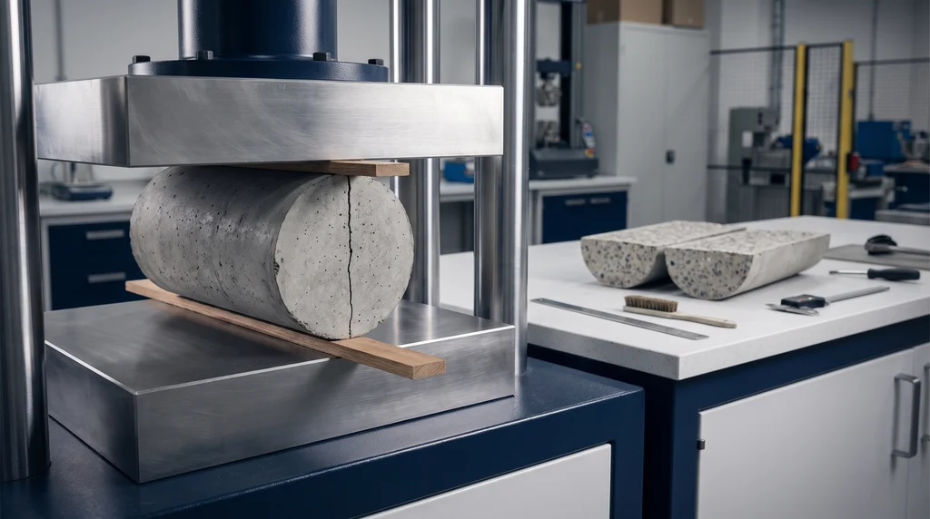
The photo shows a concrete cylinder lying between the platens, with one bearing strip on top and another underneath: the compressive force along the vertical diameter creates tension in the plane through the axis, and that is the plane in which the cylinder splits, as shown by the crack on the end face and the already failed specimen on the bench.
The method was born in Brazil. Engineer Fernando Luiz Lobo Carneiro, of the National Institute of Technology in Rio de Janeiro, presented it at the 5th Meeting of ABNT on September 16, 1943, according to the history compiled by Rocco and coworkers and by an article in the journal Transportes, published by ANPET. According to these accounts, the starting problem was moving an old church on concrete rollers, which worked lying on their sides and compressed along a generatrix, just like the cylinder in the test. In the same year, Tsuneo Akazawa arrived at the same method independently in Japan. Carneiro took the test to the meeting that founded RILEM in 1947, and it became known worldwide as the Brazilian test. ASTM standardized it for concrete in 1962, and today the same principle is used for rock, asphalt mixtures and stabilized soils, each with its own standard.
Why the cylinder fails in tension when it is compressed
The cylinder fails in tension because concrete is about ten times weaker in tension than in compression, and the diametral load creates both stresses at the same time in the vertical plane through the axis: compression in the vertical direction and tension in the horizontal direction. The tension is the first to reach the material's limit. According to elasticity theory, in a cylinder loaded by two line forces, the horizontal stress along the vertical diameter is constant and equal to exactly σ0 = 2F / (π·d·L), which is the formula in the standard; the vertical compressive stress is three times this value at the center and grows without limit near the load lines. This is the classical solution for a disc in compression, presented by Timoshenko and Goodier.
The high compressive stress is confined near the generatrices, in a region where the material is compressed in all three directions and is much stronger. Away from them, the concrete carries an almost uniform tensile stress along most of the diameter, and the crack that starts at the middle of the cylinder runs from one generatrix to the other. The result is the clean split into two halves seen in the laboratory.
A perfect line load, however, would crush the concrete under the platens. The wooden strips spread the force over a narrow band, and this changes the distribution slightly. The chart below shows the stresses along the vertical diameter of a 100 mm cylinder, calculated with Hondros' elastic solution (1959) for a load distributed over a band as wide as the strip in the standard, 0.15 d. The horizontal tensile stress is 0.97 σ0 at the center, stays between 0.88 and 0.97 σ0 over the central half of the diameter, and only becomes compressive at 78% of the radius, already close to the strips:
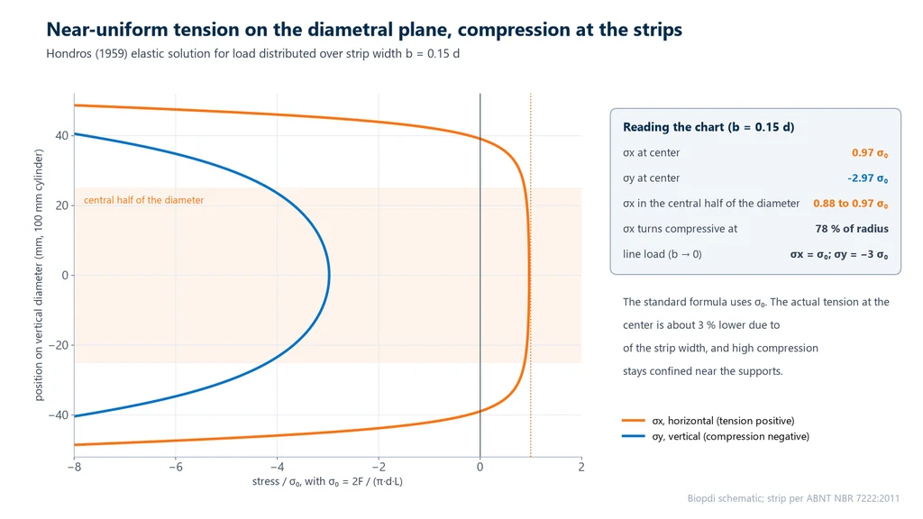
The practical consequence is that the formula in the standard is a well-founded convention, not an exact measurement. It uses the stress for a line load, and with the standard strip the actual tensile stress at the center is about 3% lower. Since every laboratory uses the same strip, the difference is the same in every test and the results are comparable. Changing the strip width changes the number, as shown in the sections on interpretation and worked examples.
Test specimens: concrete, mortar and cores
The NBR 7222 test specimen is a cylinder with a length-to-diameter ratio (L/d) between 1 and 2. In practice, this means the same cylinders used for axial compression: 10 × 20 cm or 15 × 30 cm for concrete, molded and cured according to NBR 5738, and 5 × 10 cm for cement mortar, molded according to NBR 7215. Between the moist room and the test, the specimen is kept moist, because concrete that dries at the surface develops shrinkage stresses that change the measured tensile strength. Molding, consolidation and curing are covered in the guide to the concrete test specimen and are not repeated here.
Cores drilled from the structure can also be tested, following NBR 7680 and, where applicable, NBR 5738. The test report for a core carries a caveat: drilling with a diamond core bit can damage the concrete at the surface of the cylinder and reduce the measured tensile strength, and whoever reads the result needs to know this.
The dimensions go into the formula and are therefore measured. The diameter is the average of two perpendicular diameters measured at mid-length, with a resolution of 0.1 mm; the length is measured along the axis, to 0.1 mm. When the laboratory controls the geometry of the molds, as NBR 5738 provides, nominal dimensions may be used. Unlike axial compression, the ends do not need to be capped or ground: the load is applied through the lateral surface, and the ends are left free.
Apparatus: machine, bearing strips and supplementary bar
The NBR 7222 apparatus is the compression testing machine of NBR 5739 and NBR 7215, plus the bearing strips and, when needed, a supplementary steel bar. The standard requires the failure load to fall within the range over which the machine was verified. Since NBR 5739 requires the testing laboratory to use a class 1 machine according to ABNT NBR ISO 7500-1, the same class applies in practice to the splitting tensile test; what the class means and how the machine is verified are covered in the guide to universal testing machine calibration according to ISO 7500-1 (ABNT NBR ISO 7500-1 in Brazil).
- Bearing strips. Hardboard (wood fiberboard) or particleboard, free of defects, with a length equal to or greater than the cylinder generatrix, width b = (0.15 ± 0.01)·d and thickness h = (3.5 ± 0.5) mm. For a 100 mm cylinder, the strip is 14 to 16 mm wide; for a 150 mm cylinder, 21 to 24 mm. Each strip is used for a single test.
- Supplementary bar or plate. When the machine platen is shorter than the cylinder, a machined steel bar or plate is placed between the platen and the strip, at least 50 mm thick, with contact faces flat to within 0.05 mm per 150 mm and a width at least equal to the distance from the edge of the platen to the end of the cylinder. It ensures that the force acts along the full generatrix.
- Auxiliary positioning device. Allowed, provided it does not change the result. The standard gives as an example a steel frame that holds the strips and aligns the cylinder, with a clear height smaller than the diameter.
The diagram below shows the complete setup for a 10 × 20 cm cylinder: on the left, the cross section with the two 15 mm strips and the failure plane; on the right, the side view, with the strips along the 200 mm of the cylinder and the supplementary steel bar between the cylinder and a shorter platen:
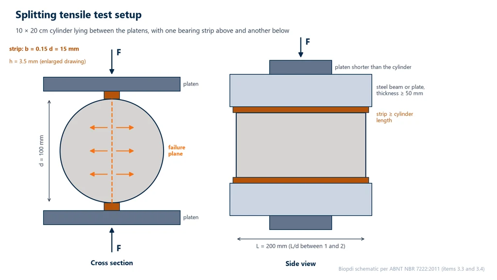
The supplementary bar solves a common geometry problem. A 15 × 30 cm cylinder lying on its side is 300 mm long, longer than the diameter of many platens. Without the bar, the platen would load only the central part of the generatrix, and the ends of the cylinder would carry no load: the force would be concentrated in the middle, and the stress calculated with the full length would come out lower than the real one. The 50 mm of steel is what keeps the bar from bending under the failure load.
Test procedure step by step
After the measurements, the NBR 7222 procedure has four steps: mark, set up, seat and load. They all serve the same purpose, which is to apply the load along two exactly opposite generatrices lying in the same vertical plane as the machine's loading axis.
- Mark. On each end of the cylinder, draw a diametral line, with both lines in the same axial plane. They show where the loaded generatrices are. Marking is not needed when the auxiliary positioning device is used.
- Set up. Place a new strip on the lower platen, the cylinder lying on it with the lines vertical, and the other strip on top of the cylinder, so that the plane of the lines coincides with the loading axis.
- Seat. Bring the platens together until they hold the cylinder in position, without significant load.
- Load. Apply the load continuously and without shock, with the tensile stress increasing at (0.05 ± 0.02) MPa/s until failure, and record the maximum force F.
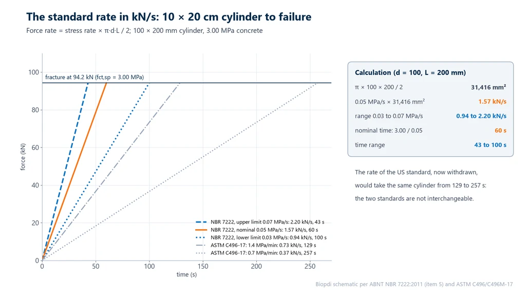
The rate is given as a stress rate so that it applies to any cylinder size, but the machine controls force. From the formula in the standard itself, the rate in N/s is the rate in MPa/s multiplied by π·d·L / 2, in mm². For a 10 × 20 cylinder, this product is 31,416 mm², and 0.05 MPa/s becomes 1.57 kN/s. The chart below shows the ramp to failure of a 3.00 MPa concrete, which fails at 94.2 kN: at the nominal rate, failure occurs at 60 s, and the limits of the range take from 43 s to 100 s:
The table gives the rate in kN/s and the expected failure load for an fct,sp of 3.0 MPa for the three usual cylinders. This is the number the operator enters in the software, and it changes with the cylinder size:
| Cylinder d × L (mm) | π·d·L / 2 (mm²) | Rate at 0.05 MPa/s (range) | F for 3.0 MPa |
|---|---|---|---|
| 50 × 100 (mortar) | 7,854 | 393 N/s (236 to 550 N/s) | 23.6 kN |
| 100 × 200 | 31,416 | 1.57 kN/s (0.94 to 2.20 kN/s) | 94.2 kN |
| 150 × 300 | 70,686 | 3.53 kN/s (2.12 to 4.95 kN/s) | 212 kN |
One detail confuses operators: the 3.53 kN/s for the 15 × 30 cylinder under NBR 7222 is the same number as for axial compression of a 10 × 20 cylinder under NBR 5739, at 0.45 MPa/s. The coincidence is purely arithmetic. A laboratory that saves "3.53 kN/s" as its default rate and changes the cylinder or the test without reviewing the test method ends up loading the 10 × 20 cylinder on its side at 0.11 MPa/s, outside the range allowed by the standard.
How to calculate splitting tensile strength
The splitting tensile strength is calculated from the maximum force and the two dimensions of the cylinder:
fct,sp = 2F / (π·d·L), with F in newtons and d (diameter) and L (length) in millimeters. This gives the result in MPa, reported to three significant figures.
The 2/π factor comes from the elastic solution described above: π·d·L / 2 is the area of an "equivalent section" that converts the force into the horizontal stress at the center. This is why the formula does not use the area of the cylinder base, π·d²/4, which only applies to axial compression. The result is reported to three significant figures, 2.79 MPa and not 2.8 or 2.788, which matches the resolution of the force and of the measured dimensions.
The NBR 7222 report (the Brazilian standard for the splitting tensile test of concrete) lists the identification and result of each specimen:
- origin, identification and number of specimens, with the recommendation of at least two per age;
- casting and test dates, and age;
- diameter and length;
- defects observed in the specimen;
- maximum force and fct,sp of each specimen, individually;
- reference to the standard and, for cores, a note on the effect of coring.
The standard does not require averaging or discarding values: the report gives the individual results. The test only yields the maximum force. There is no curve to interpret and no plateau or modulus to extract, so NBR 7222 does not require an extensometer. The force is measured by the machine's load cell, and the software records the peak at the instant the crack runs through the cylinder and the force drops all at once.
How much tension concrete can take: fct,sp, NBR 6118 and flexure
Concrete's tensile strength is about one tenth of its compressive strength: common structural concretes, from 20 to 50 MPa, have a mean direct tensile strength between 2.2 and 4.1 MPa, according to the NBR 6118 estimate. The fct,sp from NBR 7222 is higher than these values because it is an indirect tensile strength, and the design standard converts one into the other. The flexural tensile strength of prisms, used for pavements, is covered in the NBR 12142 guide.
ABNT NBR 6118:2023, the Brazilian design standard for concrete structures, defines the direct tensile strength fct from the two indirect tests: fct = 0.9·fct,sp for the splitting test and fct = 0.7·fct,f for the flexural tensile test of prisms, per NBR 12142. Without testing, it estimates the mean tensile strength as fct,m = 0.3·fck2/3 for concretes up to C50, and the lower and upper characteristic values as fctk,inf = 0.7·fct,m and fctk,sup = 1.3·fct,m. Eurocode 2 uses the same 0.9 factor and the same estimate. The table shows the calculations for common strength classes, with the last column in equivalent fct,sp, which is what you would expect to read in the test:
| fck (MPa) | fct,m (MPa) | fctk,inf (MPa) | Equivalent fct,sp (MPa) |
|---|---|---|---|
| 20 | 2.21 | 1.55 | 2.46 |
| 25 | 2.56 | 1.80 | 2.85 |
| 30 | 2.90 | 2.03 | 3.22 |
| 40 | 3.51 | 2.46 | 3.90 |
| 50 | 4.07 | 2.85 | 4.52 |
The two indirect tests do not give the same number for the same concrete. The flexural tensile strength comes out higher because only the outermost fiber of the prism reaches the maximum stress, and the less stressed material around it helps hold the crack back. In the splitting test, the whole central half of the diameter is close to the maximum stress. Hence the different factors in NBR 6118: 0.7 for flexure and 0.9 for splitting. In pavement concretes, Balbo (Revista IBRACON de Estruturas e Materiais, 2013) measured, on 244 specimens, a flexural tensile strength on average 1.32 times the splitting tensile strength. Flexural testing in general, with 3-point and 4-point bending, is covered in the flexural test guide.
The tensile strength of concrete enters design in specific checks: cracking, cracking moment, anchorage and some shear mechanisms. In the mix design of concrete pavements, the reference strength is the flexural tensile strength, not the splitting tensile strength. The ultimate tensile strength of metals, measured in direct tension, is a quantity of a different nature, tied to a ductile material, and cannot be compared with the fct,sp of a brittle material.
NBR 7222, EN 12390-6, ASTM C496 and DNIT 136
NBR 7222, the European EN 12390-6 and the American ASTM C496 use the same formula and the same principle, but differ in the bearing strip and the loading rate, so their results are not interchangeable. The table summarizes the three concrete standards:
| Item | NBR 7222:2011 | EN 12390-6:2023 | ASTM C496/C496M-17 |
|---|---|---|---|
| Status | current (reaffirmed in 04/2024) | current, replaced the 2009 edition | withdrawn on July 3, 2026, with no replacement |
| Bearing strip | hardboard, b = 0.15·d, h = 3.5 mm | hardboard (≥ 900 kg/m³), 15 mm × 4 mm | 3.2 mm plywood, about 25 mm wide |
| Loading rate | 0.05 ± 0.02 MPa/s | 0.04 to 0.06 MPa/s | 0.7 to 1.4 MPa/min (0.012 to 0.023 MPa/s) |
| Formula | 2F / (π·d·L) | 2F / (π·L·d) | 2P / (π·l·d) |
The EN 12390-6:2023 data come from the public preview of the final text (FprEN 12390-6:2023). The 2023 edition also restricted the test to cylinders with hardboard strips, after an interlaboratory program showed that cubes gave a tensile strength about 10% higher. The ASTM C496 data come from the 2017 edition, the last one before withdrawal. The difference in loading rate is large: 0.05 MPa/s is 3.0 MPa/min, 2 to 4 times the American rate, and the faster the loading, the higher the failure force a brittle material withstands. The strip width also differs: NBR makes it proportional to the diameter, while the European standard fixes it at 15 mm, which gives the same b/d ratio as the Brazilian standard on a 100 mm cylinder. Internationally, ISO 1920-4:2020 also covers the test, along with compression and flexure.
In asphalt mixtures, the same principle is applied by DNIT 136/2018-ME (a standard of DNIT, Brazil's federal transport infrastructure agency), which measures the indirect tensile strength (RT) of Marshall or gyratory-compacted specimens at 25 °C, with displacement-controlled loading at 0.8 ± 0.1 mm/s rather than stress-controlled loading. The RT sets the load for the resilient modulus test by diametral compression, per DNIT 135/2018-ME, and feeds pavement design. The concrete figures do not apply to asphalt, and vice versa. Soils stabilized with fly ash and lime have DNER-ME 181/94, and rocks have ASTM D3967-23, which tests core discs. This is why a search for "diametral compression" mixes pages on concrete, asphalt and soil: the name is the same, the standard is not.
Mortar in NBR 7222 and NBR 13279
NBR 7222 applies to mortar cast in cylinders, with the same formula, the same strips proportional to the diameter and the same loading rate. This is the case of the 5 × 10 cm cement mortar cylinders, cast as in NBR 7215 (the Brazilian standard for the compressive strength of cement), and of high-strength floor mortars, whose standard, NBR 12041, specifies simple compression and splitting tensile tests.
Masonry and rendering mortar, however, is not controlled this way. For it, the routine test is NBR 13279, on 4 × 4 × 16 cm prisms broken first in flexure and then, on the halves, in compression. Anyone looking for the tensile strength of a rendering mortar should use NBR 13279, explained in the NBR 13279 guide; NBR 7222 applies when the specimen is a cylinder.
How to interpret the standard
The text of NBR 7222 is short and gives the numbers without explaining where they come from. The points below are the ones that raise the most questions in the lab and when reading test reports, with the reasoning behind each one.
Why is fct,sp higher than the direct tensile strength?
Because, in the splitting test, the concrete in the failure plane is not only in tension: it is in horizontal tension and vertical compression, with a compression about three times the tension. In a brittle material, the crack starts at the most unfavorable defect in the stressed volume. In the direct tensile test, the entire cylinder is under the maximum stress, and the chance of a critical defect is higher; in the splitting test, only a band of the central plane is close to the maximum. The indirect result comes out higher, and NBR 6118 discounts the difference with the 0.9 factor.
Why does the strip width change the result?
Because the strip defines how the load enters the cylinder. The wider it is, the more the load spreads, the lower the tension at the center for the same force and the higher the force needed to break it. According to Hondros' solution, the tension at the center drops from 0.998 σ0 with a strip of 4% of the diameter to 0.970 σ0 with one of 15% and 0.916 σ0 with one of 25%. Tests reported by Rocco and co-workers showed that increasing the strip from 4% to 16% of the diameter raised the failure load by 25% to 30%. This is why the standard sets b = 0.15·d and forbids reusing the strip: a strip that has already been crushed is thinner and harder, and changes the contact band.
Why is the loading rate nine times lower than in NBR 5739?
Because the goal is to match the test duration, not the rate. Axial compression per NBR 5739 (the Brazilian standard for concrete compression testing) ramps at 0.45 MPa/s to about 30 MPa, which takes about 67 s; the splitting test ramps at 0.05 MPa/s to about 3 MPa, which takes about 60 s. Since the tensile strength is about one tenth of the compressive strength, so is the rate. At the compression rate, the cylinder lying on its side would break in 7 s, too fast for a reliable record of the peak and with a result inflated by the speed.
Why two specimens per age, and not one?
Because the tensile strength of concrete is more scattered than the compressive strength: it depends on the largest defect in the failure plane, and a pore or a poorly bonded aggregate in that plane brings down the value of a cylinder. With a single result, there is no way to separate the concrete from chance. The precision statement of ASTM C496, in its 2011 edition, gives an order-of-magnitude reference: a coefficient of variation of 5% between cylinders from the same batch, and two results by the same operator should not differ by more than 14% of their mean.
Does the fracture have to run through the plane of the strips?
Yes, a valid fracture is a crack in the vertical diametral plane that splits the cylinder into two halves. Crushed wedges next to the strips, inclined cracks or fracture outside the plane indicate misalignment between the cylinder and the load axis, non-parallel platens, or an irregular or reused strip. NBR 7222 does not include a list of fracture types like NBR 5739, but it requires defects to be reported; recording the fracture type helps explain an outlier.
Is the test valid for fiber-reinforced concrete?
With caution. The formula assumes a brittle material, elastic up to failure, that splits in half when the crack runs through the plane. With high steel fiber contents, the crack opens, the force drops a little and rises again, and the cylinder does not split apart. The peak is still recorded, but it no longer represents the tensile strength of a brittle material, and the result can only be compared with another concrete with the same fiber and the same content. For the post-cracking behavior of fiber-reinforced concrete, flexural tests are more widely used.
Worked examples
The examples use illustrative data, calculated with the formula and loading rate of NBR 7222:2011 and the relationships of NBR 6118:2023.
1. fct,sp of a 10 × 20 concrete cylinder. d = 100 mm, L = 200 mm, F = 87.6 kN.
- π·d·L = π × 100 × 200 = 62,832 mm².
- fct,sp = 2 × 87,600 / 62,832 = 175,200 / 62,832 = 2.788 MPa, which to three significant figures is reported as 2.79 MPa.
- Direct tensile strength per NBR 6118: fct = 0.9 × 2.79 = 2.51 MPa.
2. Loading rate and time on a 15 × 30 cylinder. d = 150 mm, L = 300 mm, failure at F = 220 kN.
- π·d·L / 2 = π × 150 × 300 / 2 = 70,686 mm².
- fct,sp = 220,000 / 70,686 = 3.11 MPa.
- Nominal rate: 0.05 × 70,686 = 3,534 N/s = 3.53 kN/s; range of 0.03 to 0.07 MPa/s: 2.12 to 4.95 kN/s.
- Time to failure: 3.11 / 0.05 = 62 s; at the limits of the range, from 44 s to 104 s.
3. Mortar in a 5 × 10 cylinder. d = 50 mm, L = 100 mm, F = 12.0 kN.
- fct,sp = 2 × 12,000 / (π × 50 × 100) = 24,000 / 15,708 = 1.53 MPa.
- Rate to program: 0.05 × 15,708 / 2 = 393 N/s, about 0.39 kN/s. A machine that cannot control such low rates stably is not suitable for this cylinder.
4. Predicting the force and choosing the machine. A laboratory will test concretes from C30 to C50, in 10 × 20 and 15 × 30 cylinders. The prediction uses NBR 6118, converting the direct tensile strength into equivalent fct,sp (dividing by 0.9), and the upper characteristic value to cover the strongest cylinders.
- C30: fct,m = 0.3 × 302/3 = 0.3 × 9.655 = 2.90 MPa; expected fct,sp = 2.90 / 0.9 = 3.22 MPa. Upper: 1.3 × 2.90 / 0.9 = 4.18 MPa.
- Force on the 10 × 20 (31,416 mm²): mean 3.22 × 31,416 = 101 kN; upper 4.18 × 31,416 = 131 kN.
- Force on the 15 × 30 (70,686 mm²): mean 3.22 × 70,686 = 227 kN; upper 4.18 × 70,686 = 296 kN.
- C50: fct,m = 0.3 × 502/3 = 4.07 MPa; upper in fct,sp = 1.3 × 4.07 / 0.9 = 5.88 MPa, or 185 kN on the 10 × 20 and 416 kN on the 15 × 30.
Conclusion: for 10 × 20 cylinders up to C50, a 200 to 300 kN machine covers the range with margin. For 15 × 30 cylinders, 300 kN is already at the limit for a C30 and is not enough for a C50: the range calls for 600 kN. In practice, the same machine also performs axial compression of the same cylinders, which requires much more force, and the capacity is usually decided by that test.
5. Two specimens of the same age. Two 10 × 20 cylinders gave 2.79 MPa and 2.95 MPa. The report gives both individual values, as the standard requires. The difference is 0.16 MPa, or 0.16 / 2.87 = 5.6% of the 2.87 MPa mean, well below the 14% that the ASTM C496 precision statement used as the limit for two results: there is no sign of a testing problem.
6. The effect of using the wrong strip. A laboratory uses the roughly 25 mm strip of the American standard on a 100 mm cylinder, b/d = 0.25 instead of 0.15. According to Hondros' elastic solution, the tension at the center, for the same force, drops from 0.970 σ0 to 0.916 σ0, a ratio of 0.916 / 0.970 = 0.944, or a 5.6% reduction. To break, the cylinder needs a higher force, and the calculated fct,sp comes out higher than the correct strip would give. The figure comes from an elastic model and serves to show the direction and order of magnitude of the error, not to correct results.
Common mistakes when applying NBR 7222
The most frequent mistakes in in-house procedures, test reports and online content come from three sources: the wrong document, the wrong number and the wrong interpretation of the result:
- Using the 2010 First Draft as the standard. The PDF of the draft ranks well in search, has no normative value and gives the bearing strip width in the wrong unit.
- Calculating the stress with the cross-sectional area. Dividing F by π·d²/4 gives a "compressive strength" that is meaningless for a cylinder lying on its side. The formula is 2F / (π·d·L). A page that ranks well in Brazil for "ensaio de compressão diametral" (splitting tensile test) makes exactly this mistake and applies F/A.
- Treating fct,sp as direct tensile strength. For design, fct = 0.9·fct,sp.
- Swapping the flexural factor for the splitting tensile factor. 0.7 applies to the fct,f of the prism; 0.9 applies to the fct,sp of the cylinder.
- Reusing the bearing strip or using the wrong width. Each strip is used only once and is 0.15 times the diameter wide: 15 mm for a 100 mm cylinder and 22.5 mm for a 150 mm cylinder.
- Programming the NBR 5739 rate. 0.45 MPa/s is the rate for axial compression, nine times higher.
- Programming the same rate in kN/s for different cylinders. 1.57 kN/s is the rate for a 10 × 20 cylinder; a 15 × 30 cylinder needs 3.53 kN/s.
- Using the ASTM C496 rate. 0.7 to 1.4 MPa/min is below the NBR minimum of 0.03 MPa/s, or 1.8 MPa/min. ASTM C496 was also withdrawn in July 2026.
- Loading without a supplementary bearing bar when the platen is too short. The ends of the cylinder carry no load, so a stress calculated with the full length is wrong.
- Misaligning the plane of the loading lines with the load axis. The fracture comes out inclined or with wedges, and the result drops. Marking the diametral lines, or using the alignment jig, prevents this.
- Letting the specimen dry before the test. The standard requires it to be kept moist between curing and testing.
- Reporting only the mean. The report gives the fct,sp of each specimen, to three significant figures.
- Applying NBR 7222 to asphalt mixtures. Asphalt follows DNIT 136/2018-ME (the Brazilian highway agency method for asphalt mixtures), with displacement control and a fixed temperature.
- Trusting the "standard canceled" notice on sales websites. Some catalogs display a generic notice on every standard; what counts is the status field of the record, which shows NBR 7222 as current.
Equipment for the NBR 7222 test
The splitting tensile test requires a compression testing machine with stable rate control at low values, from a few hundred N/s to a few kN/s, recording of the maximum force, and platens, or a supplementary bearing bar, that cover the full length of the cylinder. The Biopdi electric and hydraulic concrete compression testing machine is dedicated to compression and handles routine cylinder testing. The dual-column universal testing machine performs the same test with compression platens and the fixture required by the standard mounted between them: the hardboard bearing strips and, when needed, the supplementary bearing bar and the alignment jig. On the same frame, it also performs axial compression of cylinders and other tests.
Capacity follows exercise 4: 10 × 20 cylinders tested on their side break at around 100 to 185 kN, within the range of the 100 to 200 kN machine or the 300 kN machine; 15 × 30 cylinders of high strength classes require the 600 kN machine. The load cell of the M2 line is class 1 per ISO 7500-1:2023 (ABNT NBR ISO 7500-1 in Brazil), and the class of the assembled machine comes from the verification by the calibration laboratory. The BioLab software converts the rate in MPa/s to kN/s from the entered diameter and length, records the maximum force, calculates fct,sp and generates the report. The panel below shows the machine, the role of each part in this test and the accessory used.
The universal testing machine in the compression test
The dual-column M2 line ranges from 5 kN to 1,000 kN. In the splitting tensile test per NBR 7222, each part of the machine has a function:

- Moving crosshead applies the load at 0.05 MPa/s, without shock
- Load cell measures the force, class 1
- Compression platens cylinder on its side between the strips
- BioLab software rate in kN/s, fct,sp and report
- Control panel and emergency stop positions and stops the test
Fixtures for the compression test
The fixture below is mounted on the same machine, in place of the grips:
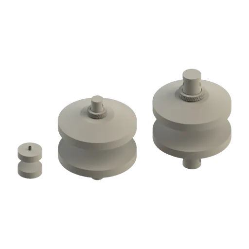
To compare the models, see the universal testing machine guide; the configuration for each standard is defined in the quote.
Standards cited: edition and status
The standards in this guide are NBR 7222, the Brazilian standards it refers to or that use its result, and the foreign equivalents. NBR 7222 was checked on October 2, 2026 in the Target catalog (a Brazilian standards distributor); the other ABNT standards, on September 30, 2026 in the same catalog. ASTM C496/C496M and ASTM D3967 were checked on October 2, 2026 on the official ASTM page; ISO 1920-4, on September 30, 2026; and EN 12390-6 through the British edition BS EN 12390-6:2023, of November 2023, which replaced the 2009 edition.
| Standard | Subject | Edition and status |
|---|---|---|
| ABNT NBR 7222 | splitting tensile strength of concrete and mortar cylinders | 2011, current (reaffirmed 04/2024) |
| ABNT NBR 5739 | compression testing of concrete cylinders; specifies the machine | 2018, current (reaffirmed 12/2023) |
| ABNT NBR 5738 | molding and curing of test specimens | 2015 (erratum 2016), current |
| ABNT NBR 7680-1 | concrete cores | 2015, current |
| ABNT NBR 6118 | design of concrete structures (fct = 0.9·fct,sp) | 2023, with amendment of 03/2026, current |
| ABNT NBR 12142 | flexural tensile strength of concrete prisms | 2010, current (reaffirmed 04/2024) |
| ABNT NBR 13279 | mortar, flexural and compressive strength | 2005, current (reaffirmed 11/2023) |
| ABNT NBR ISO 7500-1 | verification and class of the machine | 2023, current |
| EN 12390-6 | splitting tensile strength (Europe) | 2023, replaces the 2009 edition |
| ASTM C496/C496M | splitting tensile strength of concrete cylinders (USA) | C496/C496M-17, withdrawn on July 3, 2026, with no replacement |
| ISO 1920-4 | compressive, flexural and splitting tensile strength of concrete | 2020, confirmed in 2025 |
| ASTM D3967 | splitting tensile strength of rock core specimens | D3967-23, active |
| DNIT 136/2018-ME | tensile strength of asphalt mixtures | 2018 |
| DNER-ME 181/94 | soils stabilized with fly ash and lime | 1994 |
Other tests and technical references
Tests performed on the Biopdi universal testing machine



















Related technical references
NBR 5739 concrete compression test: fc calculation and the NBR 7222, NBR 12142 and NBR 6136-2 standards
ABNT NBR 5739:2018 (the Brazilian standard for concrete compression testing), reaffirmed in 2023, covers compression testing of cylindrical concrete specimens: continuous loading at 0.45 ± 0.15 MPa/s until failure and fc = 4F/(πD²), in MPa, to three significant figures. See what it requires of the machine and the specimen, the h/d correction, failure types A to G and the related standards: NBR 7222 (splitting tensile test), NBR 12142 (flexural tensile strength) and NBR 12118, withdrawn in February 2026 and replaced by NBR 6136-2:2026.
NBR 12142: flexural tensile strength of concrete prism specimens, calculation and examples
NBR 12142:2010 (in force): flexural tensile strength of concrete prisms under third-point loading. Formula, 5% rule, rate in kN/min and examples.
NBR 13279: flexural tensile and compressive strength of mortar (4 × 4 × 16 cm prisms), calculation and classification
ABNT NBR 13279:2005, the Brazilian standard for mortar strength testing, is current and was reconfirmed by ABNT in November 2023. It is Brazil's method for measuring the flexural tensile strength and the compressive strength of masonry and rendering mortars. 4 × 4 × 16 cm prisms are broken in 3-point bending over a 100 mm span at (50 ± 10) N/s, and the broken halves are tested in compression over 40 × 40 mm at (500 ± 50) N/s. Rf = 1.5·Ff·L/40³ and Rc = Fc/1,600, in MPa. See the procedure, the rejection criterion, a worked example, the classification under NBR 13281 and the force capacity the machine needs.
Frequently asked questions
What is NBR 7222?
It is the 2011 ABNT standard (Brazilian Association of Technical Standards), current and reaffirmed in April 2024, that specifies how to measure the tensile strength of concrete and mortar cylinders and cores by diametral compression, known as the Brazilian test. The cylinder is laid on its side between two wood-based bearing strips and compressed until it splits in half.
What is splitting tensile strength?
It is the indirect tensile strength fct,sp, calculated from the force that splits a cylinder laid on its side and compressed along two diametrically opposite lines. The compression generates an almost uniform horizontal tensile stress on the vertical plane through the axis, and the cylinder splits along that plane.
How do you calculate splitting tensile strength?
Use fct,sp = 2F / (π·d·L), with F in newtons and the diameter d and length L in millimeters, which gives MPa, reported to three significant figures. A 10 × 20 cm cylinder that breaks at 87.6 kN has 2.79 MPa.
How much tensile strength does concrete have?
About one tenth of its compressive strength. Per NBR 6118 (the Brazilian concrete design code), a C25 concrete has a mean direct tensile strength of 2.56 MPa and a C30, 2.90 MPa. In the splitting tensile test, common structural concretes give about 2.5 to 4.5 MPa.
What is the loading rate in NBR 7222?
The tensile stress must increase at 0.05 ± 0.02 MPa/s, continuously and without shock, until failure. For a 10 × 20 cylinder this is equivalent to 1.57 kN/s, and for a 15 × 30 cylinder, 3.53 kN/s.
What are the dimensions of the wood bearing strips?
Hardboard or particleboard, with a width of (0.15 ± 0.01) times the diameter, a thickness of (3.5 ± 0.5) mm and a length equal to or greater than that of the cylinder. For a 100 mm cylinder, the strip is 15 mm wide, and each strip is used only once.
How do you convert fct,sp into direct tensile strength?
Per NBR 6118, multiply by 0.9: fct = 0.9·fct,sp. An fct,sp of 2.79 MPa corresponds to 2.51 MPa of direct tensile strength. For the flexural tensile strength of NBR 12142, the factor is 0.7.
What is the difference between NBR 7222 and NBR 12142?
NBR 7222 breaks a cylinder laid on its side by diametral compression and gives fct,sp. NBR 12142 breaks a concrete prism in bending, with two loads at the third points of the span, and gives fct,f, which is higher. NBR 6118 converts both into direct tensile strength with 0.9 and 0.7.
What is the difference between NBR 7222 and ASTM C496?
The formula is the same. ASTM C496 used plywood strips 3.2 mm thick and about 25 mm wide and a rate of 0.7 to 1.4 MPa/min; the NBR uses a 0.15·d strip and 3.0 MPa/min, 2 to 4 times faster. ASTM C496 was withdrawn in July 2026, with no replacement.
How many test specimens does NBR 7222 require?
The standard recommends at least two specimens per test age, and the report gives the individual result of each one.
Who created the Brazilian test?
Engineer Fernando Lobo Carneiro, of Brazil's National Institute of Technology (Instituto Nacional de Tecnologia), who presented the method at ABNT on September 16, 1943. Tsuneo Akazawa arrived at the same method in Japan in the same year, independently.
Does the splitting tensile test of asphalt follow NBR 7222?
No. Asphalt mixtures follow DNIT 136/2018-ME, with a Marshall or gyratory specimen, at 25 °C and displacement-controlled loading at 0.8 ± 0.1 mm/s. The result defines the loads for the resilient modulus test.
Does the test require an extensometer?
No. NBR 7222 uses only the maximum force, and the formula does not depend on strain. All you need is a machine with force measurement verified per ISO 7500-1 (NBR ISO 7500-1 in Brazil) and rate control.
Which machine should be used for NBR 7222?
A compression testing machine or universal testing machine with compression platens, rate control at low values and a suitable capacity: for common concretes, 10 × 20 cylinders break at around 100 to 185 kN, and 15 × 30 cylinders at 230 to 420 kN.