
ABNT NBR 12142:2010 is the Brazilian standard for the flexural tensile strength of concrete on prismatic specimens (equivalent to ASTM C78). The prism, usually 150 × 150 × 500 mm, sits on a 450 mm span and is broken by two equal forces applied at the third points of the span, with the stress increasing at 0.9 to 1.2 MPa/min. When the fracture falls within the middle third, the result is fct,f = F·ℓ / (b·d²), in MPa. The 2010 edition is in force and was confirmed by ABNT in April 2024. We checked this status on 10/02/2026.
This guide is for people who run, commission or specify the test: concrete quality control laboratories, ready-mix concrete suppliers, designers and inspectors of concrete pavements. In our own words, it explains what the standard requires of the equipment, the test specimen, the procedure, the calculation and the report. It also derives the formula, shows what to do when the prism breaks outside the middle third, converts the loading rate into kN/min and works through five exercises. We checked every normative value against the full text of NBR 12142:2010. This guide does not reproduce the standard and is not a substitute for a purchased copy.
What NBR 12142 measures and when it is used
Flexural tensile strength, fct,f, is the tensile stress on the bottom face of a plain concrete prism at the moment it fails in bending, calculated with elastic beam theory. In English the same value is called flexural strength or modulus of rupture. It is an indirect measurement. Nobody pulls on the prism, but bending puts the bottom face in tension, and that is where the crack starts.
The official title is Concreto: Determinação da resistência à tração na flexão de corpos de prova prismáticos (Concrete: Determination of the flexural tensile strength of prismatic specimens). The standard belongs to the ABNT committee for cement, concrete and aggregates (CB-018). The 2nd edition, from October 2010, cancelled and replaced the 1991 edition with a technical revision. It was confirmed in 2015, 2019 and April 2024 with no change to the text. It applies to prisms molded according to NBR 5738 (the Brazilian standard for molding and curing concrete specimens). Where applicable, it also applies to prismatic cores extracted from structures according to NBR 7680 (the Brazilian standard for concrete core extraction), whose Part 2 deals specifically with the flexural tensile strength of pavement cores.
The main use is concrete pavement: highways, bus corridors, yards and industrial floors. A pavement slab works in bending under the wheel load, so it is designed on flexural tensile strength, not on the compressive fck. The test is also used in mix design studies, for concretes with mineral admixtures and fibers (where it gives the peak strength) and in research. The general theory of 3-point and 4-point bending, which applies to any material, is in our guide to flexural testing. Here we focus on what NBR 12142 requires.
Direct, splitting and flexural tension: the three measures of concrete
There are three ways to measure the tensile strength of concrete, and each gives a different number for the same concrete. Concrete is weak in tension and hard to pull directly, because clamping a brittle body in a grip concentrates stress and makes it break in the wrong place. For this reason, practice in Brazil relies on two indirect tests, both performed with a compressive force applied by the machine. The splitting tensile test has its own guide, on NBR 7222.
- Splitting tensile strength (NBR 7222:2011, the Brazilian standard for the splitting tensile test): a cylinder lying on its side is compressed along one generatrix and splits on the diametral plane. The result is fct,sp.
- Flexural tensile strength (NBR 12142:2010): the prism is bent and fails at the tension face. The result is fct,f.
Both overestimate the direct tensile strength, fct, for different reasons. In bending, the formula assumes linear stress up to failure, but concrete softens slightly before the peak. Also, only the extreme fiber reaches the maximum stress, while the less stressed material next to it still carries load. The typical order is therefore fct < fct,sp < fct,f. ABNT NBR 6118:2023, the Brazilian design standard for concrete structures, converts test results into direct tensile strength with fixed factors:
| Measure | Test | Conversion to direct tension (NBR 6118) |
|---|---|---|
| fct, direct tension | rarely tested | reference |
| fct,sp, splitting tension | NBR 7222, cylinder on its side | fct = 0.9·fct,sp |
| fct,f, flexural tension | NBR 12142, third-point loaded prism | fct = 0.7·fct,f |
The 0.7 factor corrects for the elastic assumption in the flexure formula. A report giving fct,f = 4.0 MPa does not mean the concrete withstands 4.0 MPa in direct tension. It means it withstands about 2.8 MPa. Our guide to NBR 5739 (the Brazilian standard for concrete compression testing) compares the three concrete tests side by side, including the cylinder under axial compression.
Prismatic test specimen: dimensions and span
The prismatic test specimen is a plain concrete beam with a square cross-section, molded and cured according to ABNT NBR 5738:2015. NBR 12142 does not set a single size. It sets the test geometry instead: the prism depth equals one third of the span (d = ℓ/3), with an overhang of at least 25 mm beyond each support. Table 1 of NBR 5738 turns this rule into four sizes, named by their basic dimension, which is the side of the cross-section:
| Basic dimension (mm) | Minimum length (mm) | Test span ℓ (mm) | 5 % of span (mm) |
|---|---|---|---|
| 100 | 350 | 300 | 15.0 |
| 150 | 500 | 450 | 22.5 |
| 250 | 800 | 750 | 37.5 |
| 450 | 1,400 | 1,350 | 67.5 |
In every size the span is three times the side, so each third of the span is exactly as long as the side of the prism, and the minimum length leaves 25 mm on each end. The 150 × 150 × 500 mm prism with a 450 mm span is the one in everyday use for pavement quality control. The minimum cross-section is 100 mm, and NBR 5738 limits the dimensional tolerance to less than 2 %, not exceeding 2 mm. The last column is the tolerance limit for a fracture outside the middle third, explained in the calculation section.
Molding, consolidation, initial curing for 48 h in the mold and moist curing up to the test age are covered by NBR 5738 and explained in our guide to the concrete test specimen. One consequence of molding matters for NBR 12142: the top face, finished with a screed, is the struck-off face, which is more irregular than the three faces cast against the mold. NBR 12142 requires centering lines to be drawn on this face and on the opposite one (the bottom of the mold), because these are the faces that will be on the sides during the test.
The machine and the 4-point fixture
The testing machine is the same one used for NBR 5739, the cylinder compression test, and NBR 12142 restates the requirement that comes from it: the selected force range must be such that the prism failure falls within the range for which the machine was calibrated. This matters more here than in compression, because a prism fails at a few tens of kilonewtons in a machine that often has a capacity of hundreds. What it means to verify and calibrate the machine range is covered in our guide to calibration according to ISO 7500-1 (ABNT NBR ISO 7500-1 in Brazil). In addition, the standard requires four conditions throughout the test:
- constant distance between supports and loading points;
- force normal to the prism surface, with no eccentricity;
- support reactions parallel to the direction of the force;
- force applied gradually and uniformly, without shocks.
The flexure fixture applies the force perpendicular to the top and bottom faces of the prism. It has two loading elements, coupled to the machine's spherical seat, and two support elements. The articulation logic is what most clearly separates a compliant fixture from an improvised one:
- Articulations: on top, one element pivots in all directions, with a movement of at least ±4°, and the other pivots only along the length of the prism. The supports follow the same arrangement. The force needed to move an articulation must not exceed 0.1 % of the estimated failure force, and the articulations are kept clean and lubricated.
- Rollers: supports and loading elements are cylindrical in the contact region, with a radius of (12.5 ± 0.5) mm, a length 3 to 5 mm greater than the prism width and a hardness of at least 55 HRC in that region.
- Geometry: the vertical planes through the roller axes are parallel, the distances between them do not change during the test, and the machine axis is perpendicular to the prism axis.
The diagram below was drawn for this guide and is not copied from the standard. It shows the setup to scale for the 150 mm prism: the two F/2 forces at the third points, the 450 mm span divided into three 150 mm parts, the depth d = ℓ/3, the overhangs and the type of articulation of each roller. The cross-section on the right shows the prism rotated 90°, with the struck-off face on the side. At the bottom are the internal force diagrams that explain the formula, which is the subject of the next section.
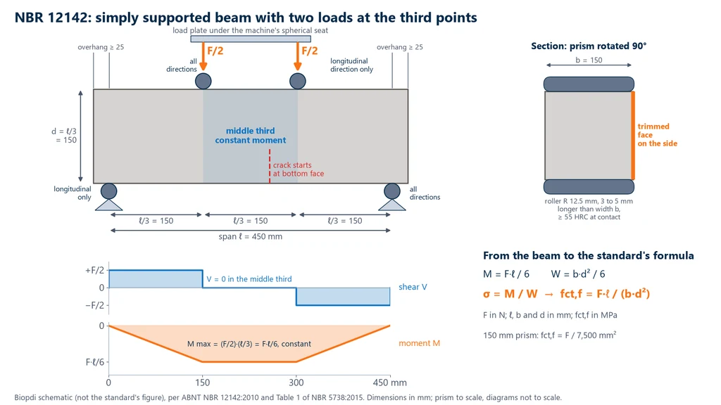
The two elements that pivot in all directions are at opposite corners. With this arrangement the fixture can follow a slightly warped prism, or one whose faces are not perfectly parallel, without twisting it. Each pair of rollers seats itself on the face it touches, and the force stays equally divided between the two loading points. A fixture with all four rollers rigid actually supports the prism at three points and introduces torsion, which causes premature failure.
Why third-point loading: deriving the formula
The NBR 12142 formula is the maximum stress in a simply supported beam under two equal loads at the third points of the span. The machine records a total force F, which splits into F/2 at each loading element, and each support reacts with F/2. The diagrams in the figure give these steps:
- Shear: F/2 between each support and the nearest load, and zero in the central third.
- Moment: increases linearly up to the first load and stays constant in the middle third, with M = (F/2)·(ℓ/3) = F·ℓ/6.
- Section modulus: a rectangular section of width b and depth d has W = b·d²/6.
- Stress at the bottom fiber: σ = M/W = (F·ℓ/6)/(b·d²/6) = F·ℓ / (b·d²).
With F in newtons and ℓ, b and d in millimeters, the result is in N/mm², which is the same as MPa. For the 150 mm prism on a 450 mm span, b·d²/ℓ = 150 × 150² / 450 = 7,500 mm², so the calculation becomes fct,f = F / 7,500. A prism that fails at 30 kN has 4.00 MPa.
The physical advantage of third-point loading is the constant moment. Throughout the middle third (150 mm on the standard prism), the bottom face is under the same maximum stress with no shear. The prism therefore fails at the weakest section in that region, wherever there is a poorly bonded aggregate or a void. In a 3-point test, with a single load at midspan, the maximum moment exists only on one line under the loading nose, and the result depends on whether or not a defect happens to sit exactly there. This is why 3-point loading tends to give higher values: NRMCA (CIP 16) reports results about 15 % higher than with 4-point loading. Our guide to flexural testing explains bending moment and section modulus in full, and our guide to the stress-strain curve covers the assumption that the material is linear up to failure.
Test procedure, step by step
The NBR 12142 procedure is short, but each step controls a known source of error. In the order they happen in the laboratory:
- Remove from curing and test wet. Prisms cured in a moist room or under water are tested right after they leave curing. If there is a wait, it must be less than 3 h, with the prism covered by a wet cloth until the test.
- Rotate 90° and center. Place the prism with its long side parallel to the fixture axis, centered on the supports using the lines drawn earlier. The faces that were sides during molding are the ones in contact with the loading and support rollers, and the struck-off face goes to the side.
- Check contact. If contact with the rollers is not perfect, grind the prism's contact surfaces.
- Load. Apply the force continuously and without shocks, with the stress increasing at 0.9 to 1.2 MPa/min, until failure. The machine records the maximum force F.
- Measure at the fractured section. Measure width and depth at the fracture section to the nearest 1 mm, each as the average of three readings.
- Locate the fracture on the tension face relative to the supports and choose the formula, as shown in the next section.
The rate is given as stress, but the machine is programmed in force. The conversion uses the same b·d²/ℓ factor. For the 150 mm prism, 0.9 MPa/min × 7,500 mm² = 6,750 N/min, or 6.75 kN/min, and 1.2 MPa/min gives 9.0 kN/min. In newtons per second, the range is 112.5 to 150 N/s. The table converts the rate for the four NBR 5738 prisms, calculated with nominal dimensions:
| Prism (mm) | b·d²/ℓ (mm²) | Force rate | In N/s |
|---|---|---|---|
| 100 × 100, ℓ = 300 | 3,333 | 3.0 to 4.0 kN/min | 50 to 67 N/s |
| 150 × 150, ℓ = 450 | 7,500 | 6.75 to 9.0 kN/min | 112.5 to 150 N/s |
| 250 × 250, ℓ = 750 | 20,833 | 18.75 to 25.0 kN/min | 312.5 to 417 N/s |
| 450 × 450, ℓ = 1,350 | 67,500 | 60.75 to 81.0 kN/min | 1,012.5 to 1,350 N/s |
Calculating the result and the fracture location
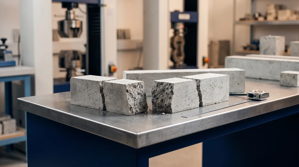
The NBR 12142 calculation (ABNT NBR 12142 is the Brazilian standard for the flexural tensile strength of concrete prisms, equivalent in principle to ASTM C78) depends on where the fracture crossed the tension face, which is the bottom face during the test. The location is read on this face and not on the top face, because that is where the crack starts and where the stress in the formula was calculated. The photo shows concrete prisms after the test: each one broke into two pieces, and the fracture surface shows the coarse aggregate cut through by the fracture. The location of this fracture, measured on the tension face, decides which of the standard's formulas applies to the result.
There are three cases, and the standard explicitly covers the first two:
- Fracture within the middle third: fct,f = F·ℓ / (b·d²).
- Fracture outside the middle third, at no more than 5 % of ℓ from it: fct,f = 3·F·a / (b·d²), where a is the average distance between the fracture line, on the tension face, and the nearest support, in mm.
- Fracture more than 5 % of ℓ from the middle third: neither formula applies, and the result is not valid.
In all three cases, F is the maximum force in N, ℓ is the span in mm, b and d are the average width and depth measured at the fracture section, in mm, and fct,f is obtained in MPa. The second formula is the same theory applied to the section where the prism actually broke: between the support and the load the moment is (F/2)·a, and dividing it by W = b·d²/6 gives 3·F·a/(b·d²). The diagram below shows the three zones on the 150 mm prism, with the 22.5 mm bands on each side of the middle third, and the lower chart shows the calculated value for the same 30 kN force as the fracture moves away from the center.
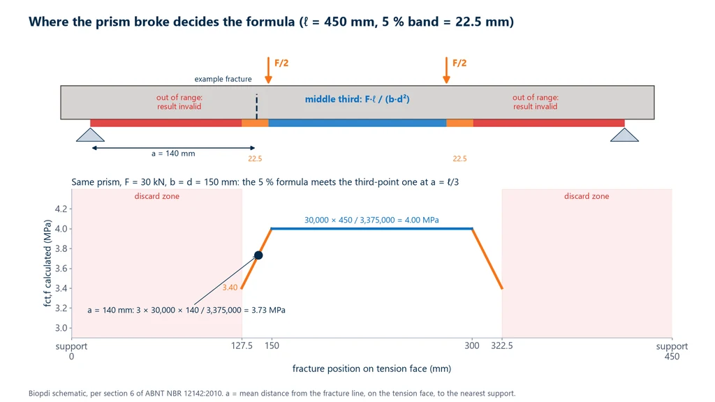
The two formulas meet at the edge of the middle third: with a = ℓ/3, 3·F·a becomes F·ℓ, and the result is the same. Outside the middle third, the actual stress at the fractured section is lower than the maximum, because the moment there is lower, and using F·ℓ/(b·d²) would overestimate the strength. More than 5 % of the span away, the fracture indicates that something other than the strength of the concrete governed the failure, such as a local defect, a poorly seated support or a misaligned prism, and the number no longer represents the material.
What the test report must contain
The NBR 12142 report records the data needed to redo the calculation and trace the test specimen. According to the standard, it includes:
- the specimen identification;
- the average width and depth, in mm, to the nearest 1 mm;
- the span between supports, in mm;
- the maximum force, in N;
- the flexural tensile strength, in MPa, expressed to three significant figures (for example, 4.37 MPa);
- defects or anomalies observed in the specimen;
- the age of the specimen, when this information is available;
- a reference to NBR 12142.
As good practice, it is worth adding the fracture location and the formula used. Without them, a result calculated with 3·F·a/(b·d²) cannot be told apart from a middle-third result, and whoever reads the report has no way to check whether the 5 % rule was applied.
What force to expect and how long the test takes
The breaking force of a prism is fct,f multiplied by b·d²/ℓ, and it is this number, not the strength in MPa, that guides the choice of the flexure fixture and of the machine's measuring range. The chart below shows, on the left, the force ramps at both ends of the loading rate range for 100 and 150 mm prisms of a concrete that breaks at 4.5 MPa; on the right, the breaking force of the four prism sizes for that same strength, compared with flexure fixtures of 10, 50 and 300 kN.
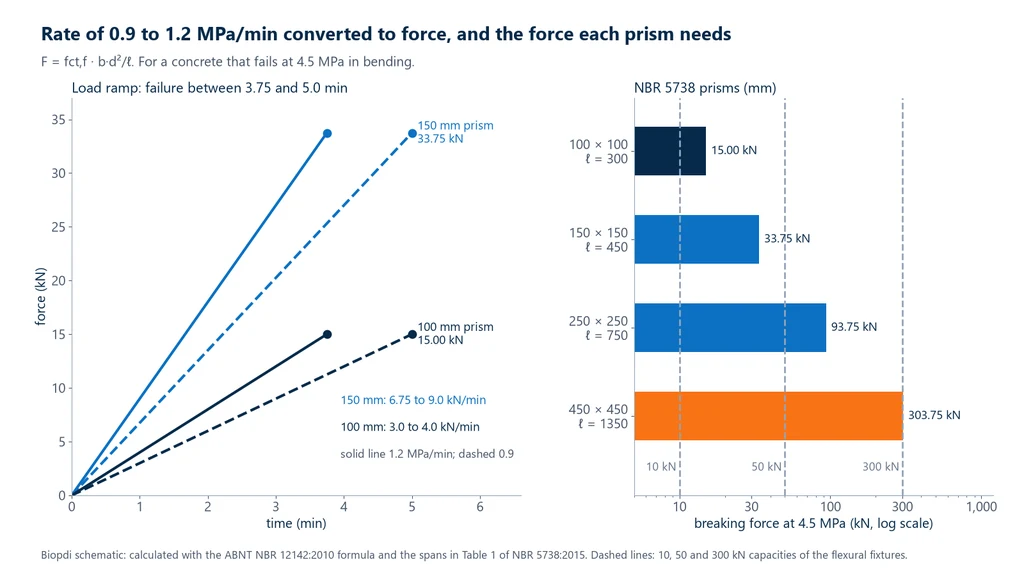
Three conclusions come from the chart. The test lasts 3.75 to 5.0 min for any prism size, because the rate is given in stress: the time is the strength divided by the rate. The 150 mm prism, the routine one, breaks in the 30 to 40 kN range, and the 100 mm prism below 20 kN. And the 450 mm prism at 4.5 MPa requires 303.75 kN, slightly above 300 kN: large prisms require checking the capacity of the entire setup, not just that of the machine.
How to interpret the standard
NBR 12142 has five pages of technical text, and several of its requirements only make sense once you know why they exist. This section explains the points that raise the most questions in the laboratory and on the job site.
Why is the prism rotated 90° from its casting position?
Because the struck-off top face, finished with a screed, has ripples and dragged aggregate, and the bottom face of the mold may have small imperfections from the mold. The side faces were cast against flat walls and are the most regular. Loading or supporting an irregular face concentrates the force on a few points of the roller, creates local stresses and can trigger the crack early. By rotating the prism, the four rollers bear on flat faces, and the tensile stress stays uniform across the width. The same reasoning applies to mortar, whose 4 × 4 × 16 cm prism is also rotated in NBR 13279.
Why must the prism be moist at the time of testing?
The surface of a prism that is drying starts to shrink while the core is still saturated. The shrinkage of the outer layer is restrained by the core and generates tension at the surface, exactly where flexure will produce tension. This stress adds to the test stress and the prism breaks at a lower force. That is why the standard limits the waiting time to less than 3 h and requires a wet cloth: a batch of prisms left in the sun on the bench loses measured strength without any change in the concrete.
Why measure b and d at the fracture section instead of using nominal dimensions?
Because the depth is squared in the formula. A prism with an actual depth of 148 mm instead of 150 mm has a b·d² about 2.6 % smaller (148² / 150² = 0.974), and using 150 mm would underestimate fct,f by 2.6 %. Measuring where the prism broke, with three readings to the nearest 1 mm, ensures that the section used in the calculation is the one that actually carried the load.
What should be done with a fracture beyond the 5 % band?
Record the specimen as broken outside the conditions of the standard and do not use the number. NBR 12142 only provides formulas for the two valid situations, and the anomaly goes into the report. If several fractures in a batch fall outside the band, the problem is rarely the concrete: it is usually a misaligned support, a seized roller, a warped prism or incorrect centering, and the fixture should be inspected before the next batch.
Why does flexure give a higher value than direct tension?
Because the formula assumes that stress increases linearly from the neutral axis to the face, all the way to fracture. In real concrete, the most highly stressed region is already microcracked near the peak and transfers stress to the neighboring, less stressed material. The actual stress in the extreme fiber is lower than the calculated one, and the value from the formula ends up above the direct tensile strength. This is the difference that NBR 6118 (the Brazilian design code for concrete structures) corrects with the 0.7 factor.
Do 100 mm and 150 mm prisms give the same result?
Not necessarily. The flexural strength of concrete has a size effect: larger prisms tend to give lower fct,f, because they have more volume under maximum stress and a greater chance of containing a critical flaw (NRMCA, CIP 16). NBR 5738 (the Brazilian standard for molding and curing concrete specimens) allows all four sizes, but a given job-site control program should always use the same one, and a correlation established with 150 mm prisms does not hold for 100 mm prisms.
Is NBR 12142 current or has it been withdrawn?
It is current. The standard's page in the catalog of Target, an ABNT reseller, shows the word "Vigente" (current) in the "Situação" (status) field and the history of confirmations in 2015, 2019 and April 2024. The same page displays a generic notice that the 10/2010 edition "was canceled", which the site shows on every standard and which does not reflect the status of this one. The correct citation remains ABNT NBR 12142:2010, checked on 10/02/2026.
Concrete pavement: design strength and mix proportioning
In plain concrete pavement, the design strength is the characteristic flexural tensile strength, fctM,k, measured on prisms molded according to NBR 5738 and broken according to NBR 12142. The Rigid Pavement Manual of DNIT (Brazil's National Department of Transport Infrastructure; publication IPR 714, 2005) recommends 28-day fctM,k values in the 4.5 MPa range, considers that values of 5.0 MPa or more call for rigorous technological control, and allows design ages between 28 and 90 days. The same manual considers the two-point (third-point) loading method, which is the NBR 12142 method, more representative and on the safe side.
Two DNIT standards link the test to the job site:
- DNIT 054/2004-PRO (mix design): the target mean strength is fctM,j = fctM,k + 0.84·Sd, where Sd is the mix design standard deviation. The 0.84 factor corresponds to accepting that 20 % of results fall below the characteristic value. The compressive fck may only be used as a criterion when there is a reliable correlation with flexural tensile strength, obtained with materials similar to those used on the job.
- DNIT 047/2004-ES (construction): concrete acceptance is based on the design fctM,k, with prisms per NBR 5738 and NBR 12142, or on the equivalent fck, provided the correlation has been determined with the job materials.
The reason for controlling by compression is practical: breaking cylinders per NBR 5739 (the Brazilian standard for concrete compression testing) is faster and cheaper than breaking 30 kg prisms. But the correlation between fct,f and fc depends on the aggregate, its texture and particle shape, and therefore does not transfer from one job to another. Prisms are still needed to build and verify this correlation.
Estimating flexural tensile strength from fck: only as an order of magnitude
Without testing, NBR 6118 estimates the mean tensile strength of concrete from fck, for classes up to C50, as fct,m = 0.3·fck2/3, with fctk,inf = 0.7·fct,m. Inverting the flexure factor, fct,m / 0.7 gives an order of magnitude of what a prism should read. The inversion is illustrative, and the standard does not present it as a design rule. The table shows the calculated values:
| fck (MPa) | fct,m (MPa) | fctk,inf (MPa) | Estimated fct,f (MPa) |
|---|---|---|---|
| 25 | 2.56 | 1.80 | 3.66 |
| 30 | 2.90 | 2.03 | 4.14 |
| 35 | 3.21 | 2.25 | 4.59 |
| 40 | 3.51 | 2.46 | 5.01 |
| 45 | 3.80 | 2.66 | 5.42 |
The values fall between 12 % and 15 % of fck, within the 10 % to 20 % of compressive strength range that NRMCA (CIP 16) gives for flexural strength, depending on the type, size and volume of coarse aggregate. They are useful for checking whether a test result is plausible and for estimating the breaking force before setting up the test, never for replacing the prism in pavement quality control.
NBR 12142, ASTM C78 and EN 12390-5
The third-point loaded prism test exists in the main foreign standards, with the same principle and different parameters. The equivalent American standard is ASTM C78/C78M, in the C78/C78M-22 edition, active as of 10/02/2026; the center-point loading variant is ASTM C293/C293M. In Europe, EN 12390-5:2019 adopts two-point loading as the reference method and allows center-point loading as an alternative. ISO 1920-4:2020 also covers the flexural test of hardened concrete. The table summarizes the differences that most affect the number:
| Item | NBR 12142:2010 | ASTM C78/C78M-22 | EN 12390-5:2019 |
|---|---|---|---|
| Loading | third-point loading | third-point loading | two-point (reference) or center-point |
| Stress rate | 0.9 to 1.2 MPa/min | 125 to 175 psi/min (about 0.86 to 1.21 MPa/min) | 0.04 to 0.06 MPa/s (2.4 to 3.6 MPa/min) |
| Typical prism | 150 × 150 × 500 mm, ℓ = 450 mm | span equal to 3 times the depth | 150 mm cross section is typical |
| Middle-third formula | F·ℓ/(b·d²) | P·L/(b·d²) | F·ℓ/(d1·d2²) |
ASTM C78 and NBR 12142 are practically interchangeable in principle, formula and rate. EN 12390-5 loads two to three times faster, which tends to give slightly higher values. A result from a foreign test report can only be compared with a Brazilian one if the method, the prism size and the rate are the same, and the report must cite the standard actually applied.
Solved examples
Unless stated otherwise, the examples use the 150 × 150 × 500 mm prism tested on a 450 mm span. The calculations are done by hand, with rounding only at the end.
1. Fracture in the middle third, with measured dimensions. The prism broke in the middle third at F = 30.0 kN. At the fracture section, b = 151 mm and d = 150 mm (each the average of three readings). fct,f = 30,000 × 450 / (151 × 150²) = 13,500,000 / 3,397,500 = 3.97 MPa, to three significant figures. With the nominal 150 mm dimensions, the result would be 4.00 MPa. The difference is small here, but it shows why the standard requires measuring: a 1 mm error in the width changes the third digit.
2. Fracture outside the middle third. Another prism from the same batch broke at F = 30.0 kN, with b = d = 150 mm, and the fracture on the tension face was a = 140 mm from the nearest support. The middle third starts 150 mm from the support, so the fracture is 10 mm outside it, within the limit of 5% × 450 = 22.5 mm. fct,f = 3 × 30,000 × 140 / (150 × 150²) = 12,600,000 / 3,375,000 = 3.73 MPa. If the fracture had been 120 mm from the support, 30 mm outside the middle third and so beyond 22.5 mm, the result would not be valid.
3. Programming the machine. A laboratory tests 100 mm prisms (300 mm span) and 150 mm prisms. For the 100 mm prism, b·d²/ℓ = 100 × 100² / 300 = 3,333 mm², and the loading rate range is 0.9 × 3,333 = 3,000 N/min to 1.2 × 3,333 = 4,000 N/min, or 50 to 67 N/s. Programmed at the center of the range, 1.05 MPa/min, the machine applies 3.5 kN/min to the 100 mm prism and 7.9 kN/min to the 150 mm prism. A 4.5 MPa concrete fails after 4.5 / 1.05 = 4.3 min in both cases. A test that ends in 1 min points to a wrong loading rate, not to a different concrete.
4. Pavement mix design and choice of fixture. The design calls for fctM,k = 4.5 MPa, and the ready-mix supplier works with a mix standard deviation Sd = 0.45 MPa (illustrative value). Under DNIT 054/2004-PRO (the Brazilian federal highway agency's procedure for rigid pavement mix design), fctM,j = 4.5 + 0.84 × 0.45 = 4.5 + 0.378 = 4.88 MPa. For the 150 mm prism, the expected mean failure load is 4.878 × 7,500 = 36,585 N, or about 36.6 kN. A 50 kN flexural fixture works at 73% of its capacity at that mean, with headroom for the strongest prisms in the batch. The 300 kN fixture can also take the load, but then the verified range of the load cell must include 30 to 45 kN, which is checked on the calibration certificate. If the project used 450 mm prisms, the mean load would be 4.878 × 67,500 = 329 kN, above 300 kN.
5. From flexural to direct tensile strength. A batch had a mean fct,f = 4.40 MPa. Under NBR 6118 (the Brazilian code for the design of concrete structures), fct = 0.7 × 4.40 = 3.08 MPa. For a concrete with fck = 35 MPa, the estimate without testing is fct,m = 0.3 × 352/3 = 0.3 × 10.70 = 3.21 MPa. The two values are close, which confirms the order of magnitude, but for the pavement the deciding value is the test result, obtained with the actual aggregate.
Common mistakes when applying NBR 12142
Most bad results come from test execution and from misreading the standard, not from the concrete. The most frequent mistakes, all explained in the previous sections:
- Using F·ℓ/(b·d²) for every fracture without checking its location, or accepting a fracture more than 5% of the span outside the middle third (22.5 mm for the 150 mm prism).
- Measuring the fracture location on the top face instead of the tension face.
- Using nominal b and d instead of the average of three measurements at the fracture section.
- Testing the prism dry, or leaving it out of curing for more than 3 h without a wet cloth.
- Supporting or loading on the troweled (finished) face instead of turning the prism 90°.
- Using a fixture with all four rollers rigid, which twists the prism, or with joints locked by dirt.
- Programming the rate in mm/min, or in stress without converting it to force for the prism size, or applying the load with shocks.
- Breaking specimens outside the machine's calibrated range, for example 35 kN on a scale verified only from much higher values.
- Comparing 3-point results with 4-point results, or results from prisms of different sizes.
- Treating fct,f as direct tensile strength in design, forgetting the 0.7 factor of NBR 6118.
- Transferring an fct,f × fck correlation from another project, against what the DNIT standards require.
- Citing the wrong standard: search summaries and commercial pages sometimes attribute this test to other standard numbers or to a loading rate range other than 0.9 to 1.2 MPa/min. The Brazilian standard for flexural testing of concrete prisms is NBR 12142, and the one for mortar is NBR 13279.
Equipment for NBR 12142
The test requires a machine with continuous load control, able to apply a few kilonewtons per minute without shock, with a load cell verified in the force range of the prism, and a flexural fixture built as the standard specifies, with the joints and rollers described above. The Biopdi universal testing machine works with 10, 50 and 300 kN flexural fixtures, and the product page lists ABNT NBR 12142:2010 among the flexural standards covered and the four-point flexural test among the fixtures. The exact fixture configuration for the standard (rollers, joints and span) is defined in the quote.
From the calculations in the section on expected load, 100 and 150 mm prisms fail below 50 kN, and the 5 to 50 kN dual-column machine covers that load. Labs that also break the NBR 5739 cylinders on the same frame need a capacity of hundreds of kilonewtons, such as the 300 kN machine, and then the load cell must also be verified in the low range of the prism, as explained in the load cell guide. The M2 line load cell is class 1 under ISO 7500-1 (ABNT NBR ISO 7500-1:2023 in Brazil). The Biopdi electric and hydraulic concrete compression testing machine is dedicated to compression and handles cylinder testing, not flexural testing of prisms. The BioLab software controls the load ramp, records the maximum force and generates the report. The panel below shows the machine, the role of each part in the NBR 12142 test and the flexural accessories.
The universal testing machine in the flexural test
The M2 dual-column line ranges from 5 kN to 1,000 kN; for 100 and 150 mm prisms, the load stays below 50 kN. In the NBR 12142 test, each part of the machine has a function:

- Moving crosshead applies the 0.9 to 1.2 MPa/min ramp converted to kN/min
- Load cell class 1, verified in the prism's force range
- Flexural fixture 4-point, loads at the third points of the span
- Deflectometer optional, for deflection measurement in research
- BioLab software maximum force, fct,f and report
- Control panel and emergency stop positions and stops the test
Fixtures for the flexural test
The fixtures below are mounted on the same machine, according to the prism size and the expected load:
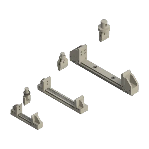
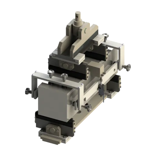
To compare the models, see the universal testing machine guide; the configuration for each standard is defined in the quote.
Standards cited: edition and status as of October 2, 2026
The table lists the standards cited in this guide. NBR 12142 and ASTM C78 were checked on October 2, 2026, in the Target catalog entry (a Brazilian standards distributor) and in the ASTM store; the other ABNT standards on September 30, 2026, in the Target catalog; the DNIT standards in the files published on the Brazilian government portal gov.br.
| Standard | Subject | Edition and status |
|---|---|---|
| ABNT NBR 12142 | concrete, flexural tensile strength of prisms | 2010, current (reaffirmed 04/2024) |
| ABNT NBR 5738 | casting and curing of test specimens | 2015 (erratum 2016), current (reaffirmed 04/2024) |
| ABNT NBR 5739 | compression of cylinders and testing machine | 2018, current (reaffirmed 12/2023) |
| ABNT NBR 7680-2 | drilled cores, flexural tensile strength | 2015 |
| ABNT NBR 7222 | splitting tensile strength | 2011, current (reaffirmed 04/2024) |
| ABNT NBR 6118 | design of concrete structures | 2023, with amendment of 03/2026, current |
| ABNT NBR ISO 7500-1 | verification and class of the machine | 2023, current |
| DNIT 054/2004-PRO | rigid pavement, mix design | 2004 |
| DNIT 047/2004-ES | rigid pavement, construction | 2004 |
| ASTM C78/C78M | flexure with third-point loading (USA) | C78/C78M-22, active |
| EN 12390-5 | flexural strength of hardened concrete (Europe) | 2019 |
| ISO 1920-4 | compressive, flexural and splitting tensile strength | 2020, confirmed in 2025 |
Other tests and technical references
Tests performed on the Biopdi universal testing machine



















Related technical references
NBR 13279: flexural tensile and compressive strength of mortar (4 × 4 × 16 cm prisms), calculation and classification
ABNT NBR 13279:2005, the Brazilian standard for mortar strength testing, is current and was reconfirmed by ABNT in November 2023. It is Brazil's method for measuring the flexural tensile strength and the compressive strength of masonry and rendering mortars. 4 × 4 × 16 cm prisms are broken in 3-point bending over a 100 mm span at (50 ± 10) N/s, and the broken halves are tested in compression over 40 × 40 mm at (500 ± 50) N/s. Rf = 1.5·Ff·L/40³ and Rc = Fc/1,600, in MPa. See the procedure, the rejection criterion, a worked example, the classification under NBR 13281 and the force capacity the machine needs.
NBR 5739 concrete compression test: fc calculation and the NBR 7222, NBR 12142 and NBR 6136-2 standards
ABNT NBR 5739:2018 (the Brazilian standard for concrete compression testing), reaffirmed in 2023, covers compression testing of cylindrical concrete specimens: continuous loading at 0.45 ± 0.15 MPa/s until failure and fc = 4F/(πD²), in MPa, to three significant figures. See what it requires of the machine and the specimen, the h/d correction, failure types A to G and the related standards: NBR 7222 (splitting tensile test), NBR 12142 (flexural tensile strength) and NBR 12118, withdrawn in February 2026 and replaced by NBR 6136-2:2026.
NBR 7222: splitting tensile test, fct,sp calculation, bearing strips and loading rate in kN/s
NBR 7222:2011 measures the tensile strength of concrete and mortar by diametral compression: fct,sp = 2F/(π·d·L) at 0.05 MPa/s. Strips, calculation, examples and machine.
Frequently asked questions
What is NBR 12142?
It is the ABNT (Brazilian) standard that defines the flexural tensile strength test of concrete on prismatic test specimens. The prism is supported as a simple beam and broken by two equal forces at the third points of the span, with the stress increasing at 0.9 to 1.2 MPa/min. The current edition is from 2010, reaffirmed by ABNT in April 2024.
What is the flexural tensile strength of concrete?
It is the tensile stress on the bottom face of a concrete prism at the moment it fails in bending, calculated by beam theory and called fct,f (also known as modulus of rupture). It is an indirect measure of tensile strength and is higher than the direct tensile strength: under NBR 6118, fct = 0.7·fct,f.
How do you calculate the flexural tensile strength?
With the fracture in the middle third, fct,f = F·ℓ/(b·d²), with F in N and ℓ, b and d in mm, which gives MPa. For the 150 × 150 mm prism on a 450 mm span, fct,f = F/7,500: a failure at 30 kN gives 4.00 MPa.
What if the prism breaks outside the middle third?
If the fracture is outside the middle third by no more than 5% of the span (22.5 mm on a 450 mm span), use fct,f = 3·F·a/(b·d²), where a is the distance from the fracture, on the tension face, to the nearest support. Beyond that, the result is not valid.
What is the size of a prismatic concrete test specimen?
The usual size is 150 × 150 × 500 mm, tested on a 450 mm span. NBR 5738 also allows cross sections of 100, 250 and 450 mm, with spans of 300, 750 and 1,350 mm, always with the span equal to three times the side.
Which standard covers the prismatic test specimen?
Casting and curing follow ABNT NBR 5738:2015 (the Brazilian standard for casting and curing concrete specimens), which also sets the dimensions and spans of the prisms. The flexural test follows NBR 12142:2010, and prismatic cores extracted from pavements follow NBR 7680-2.
What is the loading rate in NBR 12142?
The stress must increase continuously and without shocks at 0.9 to 1.2 MPa/min. For the 150 mm prism this is 6.75 to 9.0 kN/min; for the 100 mm prism, 3.0 to 4.0 kN/min.
Why does the test use two loads at the third points instead of one at the center?
Because the bending moment is constant between the two loads, so the prism breaks at the weakest section anywhere in the middle third. With center-point loading, the maximum moment is concentrated on a single line, and the result is usually higher, by about 15% according to the NRMCA.
What is the difference between NBR 12142 and NBR 7222?
NBR 7222 measures splitting tensile strength on cylinders laid on their side, and NBR 12142 measures flexural tensile strength on prisms. NBR 6118 converts both to direct tensile strength: 0.9·fct,sp and 0.7·fct,f.
How does NBR 12142 relate to NBR 5739?
NBR 5739 (the Brazilian standard for concrete compression testing) covers breaking cylinders in compression and defines the testing machine that NBR 12142 uses. For pavements, DNIT (Brazil's federal highway agency) only accepts controlling the concrete by compressive strength when there is a correlation between the two strengths established with the project's materials.
What flexural tensile strength is used for concrete pavements?
The DNIT Rigid Pavement Manual (2005) recommends fctM,k of around 4.5 MPa at 28 days, with a design age between 28 and 90 days. The mix design targets the mean fctM,j = fctM,k + 0.84·Sd, according to DNIT 054/2004-PRO.
Is NBR 12142 equivalent to ASTM C78?
In principle, yes: both use third-point loading, the same formula and practically the same rate, 0.9 to 1.2 MPa/min in the NBR and 125 to 175 psi/min in ASTM C78/C78M-22. The nominal dimensions and some details of the fixture and the report differ.