
The triaxial test is the laboratory test that measures the shear strength and deformability of soil by compressing to failure a cylindrical specimen wrapped in a membrane and confined by pressurized water, with drainage under control. Also called the triaxial compression test, it is performed in a triaxial cell and also measures the pore water pressure in the soil. The water applies the confining stress σ3 in all directions. The press piston adds a vertical stress, the deviator stress σd = P / A, where A is the corrected area, so the major principal stress becomes σ1 = σ3 + σd. Because drainage is controlled and pore pressure is measured, the test gives the soil's cohesion and friction angle in total stresses (c, φ) or effective stresses (c', φ'). The three classic types are UU (unconsolidated undrained, ASTM D2850), CU (consolidated undrained, ASTM D4767) and CD (consolidated drained, ASTM D7181).
Of all laboratory tests, it comes closest to the stress state of soil in the field, because it applies axial and radial loads at the same time and lets the failure plane form where the soil is weakest. The results are used to design foundations, slopes, embankments on soft clay, earth dams, tailings dams, retaining structures and excavations. This guide covers the principle, the test types, the step-by-step procedure, the formulas and their corrections, a complete CU example worked by hand, interpretation, common mistakes, the equipment and the standards (with the current edition). It ends with a study summary and short UU, B-value and CD exercises.
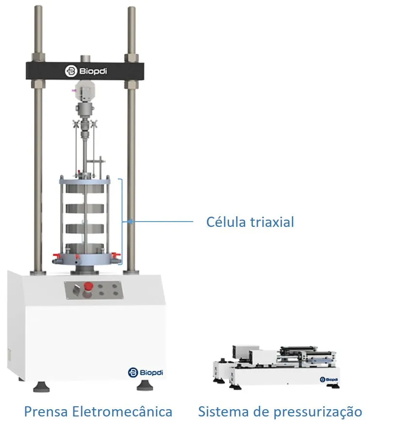
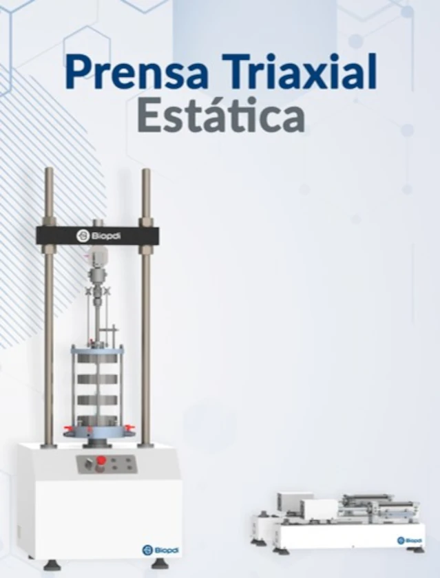
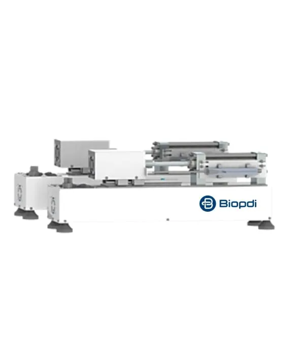
The photo shows the Biopdi static triaxial testing system: the electromechanical press applies the axial force through the piston, the acrylic triaxial cell confines the test specimen, and the pressure system beside it controls the water pressures.
What the triaxial test is and what it measures
The triaxial test is a soil strength test in which a cylindrical specimen is subjected to controlled stresses in three directions, with drainage and pore pressure under the operator's control. The name (triaxial testing) is explained further below; in practice the test is axisymmetric. The two horizontal stresses are equal and equal to σ3, the water pressure in the cell, and the vertical stress is σ1. The difference between them, σ1 − σ3, is the deviator stress σd, also called deviatoric stress. This is the stress that shears the soil, because a pressure equal in all directions only compresses it and does not distort it. Triaxial equipment for soils was developed in the 1930s, with Arthur Casagrande at Harvard among the pioneers, and the method was systematized by Bishop and Henkel in 1957.
Soil is a skeleton of grains with water and air in the pores. The part of the load carried by the grains is the effective stress, defined by Terzaghi as σ' = σ − u, where u is the pore water pressure (pore pressure), the pressure of the water in the pores. Effective stress governs the shear strength of soil. That is why the triaxial test measures u: with the pore pressure known, results can be expressed in effective stresses, which apply to any loading condition in the field.
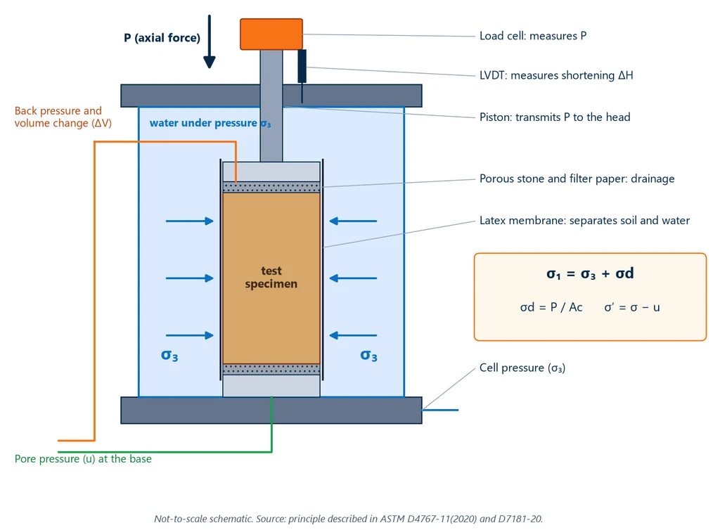
The diagram below shows how each quantity is applied and measured inside the cell: the pressurized water around the specimen, the membrane separating the soil from the water, the porous stones that allow drainage, the piston with the load cell and the LVDT, and the two hydraulic lines, back pressure at the top and pore pressure at the base.
Two advantages set the triaxial test apart from other soil strength tests. The first is drainage control: the cell valves decide whether water can leave the specimen in each stage. The second is pore pressure measurement. In the direct shear test, which is simpler and cheaper, drainage is not controlled as precisely, pore pressure is not measured and the failure plane is imposed by the split box. In the triaxial test, failure occurs on the weakest plane of the soil, as in the field. The general concept of shear stress is covered in the article on the shear test.
With suitable equipment, the same test also gives the soil's deformability. The stress-strain curve gives the deformation modulus, usually the secant modulus E50, measured at 50% of the maximum deviator stress; with the volume change measured in the drained test, Poisson's ratio can also be obtained. The main result, however, is the set of shear strength parameters of the Mohr-Coulomb failure envelope: cohesion (c or c') and internal friction angle (φ or φ').
In short, depending on the test type, the triaxial test gives:
- c and φ, cohesion and friction angle in total stresses;
- c' and φ', the same parameters in effective stresses (CU with measured pore pressure, and CD);
- su, the undrained shear strength (UU and unconfined compression);
- Skempton's A and B parameters, which describe pore pressure generation;
- E50 modulus, related to the modulus of elasticity, and Poisson's ratio (the latter in the CD test, with volume change measured);
- stress path, the path of total and effective stresses up to failure.
The triaxial test is one of the set of laboratory tests that characterize a soil for design. Index tests (particle size distribution, Atterberg limits, particle density) identify and classify the soil; the compaction test defines the working moisture content and density; the CBR test measures bearing capacity for pavements; the consolidation test measures compressibility and settlement; and the direct shear test (ASTM D3080) and the triaxial test measure shear strength.
What does triaxial mean?
Triaxial means that the specimen is under three principal stresses: the vertical stress σ1, applied by the piston, and two horizontal stresses, σ2 and σ3, applied by the water in the cell. Since the two horizontal stresses are equal (σ2 = σ3), the conventional test is axisymmetric. The true triaxial test, with three different stresses, uses a cubical or three-axis cell and is limited to research and special projects.
Study summary
The table below gathers, in six rows, the points of the triaxial test that come up most often in exams and reports. Each is detailed in the following sections.
| Point | Summary |
|---|---|
| What it measures | shear strength (c, φ, c', φ' or su), deformability and pore pressure |
| Stresses | σ3 = cell pressure; σd = P / A (piston); σ1 = σ3 + σd |
| Types and standards | UU (ASTM D2850, ISO 17892-8), CU (ASTM D4767, ISO 17892-9), CD (ASTM D7181, ISO 17892-9) |
| Failure envelope | τf = c' + σ' · tan φ' (Mohr-Coulomb) |
| Saturation | B = Δu / Δσ3 ≥ 0.95 in CU and CD tests |
| Test specimens | at least three related tests per ISO 17892-9, at different confining stresses |
Types of triaxial test: UU, CU and CD
The test has two stages, consolidation and shearing, and the abbreviation says what happens in each. The first letter indicates whether the specimen was consolidated under the confining stress before shearing (C, for consolidated) or not (U, for unconsolidated); in Portuguese, some texts use "consolidado" instead of "adensado", with the same meaning. The second letter indicates whether shearing was drained (D, drained) or undrained (U, undrained). CU and CD tests usually start with a saturation stage, explained in the step-by-step procedure further below.
Brazilian technical literature also uses Casagrande's nomenclature, based on relative speed: quick test (Q, for quick) for UU, consolidated quick test (R) for CU and slow test (S, for slow) for CD. All three are compression tests, with the vertical stress greater than the horizontal. There is also the triaxial extension test, in which the vertical stress is lower than the horizontal. Drained or undrained, it represents stress relief in excavations, tunnels and shafts; it has no ASTM standard of its own, and ISO 17892-9 lists it among the special procedures it does not fully cover.
UU: unconsolidated undrained
In the UU test the valves stay closed the whole time. The specimen receives the confining stress and is sheared right afterwards, without consolidating or draining. Since pore pressure is normally not measured, the result is expressed in total stresses. In saturated clay, increasing σ3 with drainage closed only raises the pore pressure by the same amount, and the effective stress does not change: that is why all specimens fail at the same deviator stress. The envelope is horizontal, with φu = 0, and the result is the undrained shear strength su = (σ1 − σ3)f / 2. With no saturation or consolidation, it is the shortest of the three. In the D2850-03a edition, the one we checked, the specimen rests for about 10 minutes under cell pressure before compression, and the rate is on the order of 1% per minute for plastic soils and 0.3% per minute for brittle soils, so that the peak is reached in 15 to 20 minutes; check these values in the current edition, D2850-26. The UU test serves short-term problems, in which construction loads the soil faster than the water can drain out: end of construction of an embankment on soft clay and rapid excavation, for example. The standard is ASTM D2850.
CU: consolidated undrained
In the CU test the specimen is saturated, consolidated with drainage open to the desired effective stress and then sheared with drainage closed, measuring the pore pressure. A single test gives the total parameters (c, φ) and the effective parameters (c', φ'), plus Skempton's A parameter, which describes how the soil generates pore pressure when sheared. Because it is faster than the CD test and delivers the effective parameters, it is the type most often requested for dams, tailings stacks and slopes. In tailings and loose saturated soils, the contractive behavior measured in the CU test is an input to liquefaction susceptibility assessment. The standard is ASTM D4767.
When consolidation is isotropic, with the same pressure in all directions, the test is called CIU (consolidated isotropic undrained). When it is anisotropic, with the vertical stress greater than the horizontal to reproduce the in situ stress state of the soil, it is CAU (consolidated anisotropic undrained). CU is the generic name; CIU and CAU indicate how consolidation was done. ASTM D4767 covers only isotropic consolidation, that is, CIU. ISO 17892-9:2018 provides for isotropic or anisotropic consolidation before drained or undrained shearing, and therefore also covers CAU; consolidation with zero lateral strain (K0) appears in it as a special procedure, not fully covered. In that case, the procedure must be agreed with the laboratory and stated in the report. For the drained test, ASTM D7181-20 also provides for anisotropic consolidation (CAD).
CD: consolidated drained
In the CD test drainage stays open in both stages, and shearing is slow enough for the pore pressure generated by loading to dissipate: excess u stays close to zero and total and effective stresses practically coincide. The test gives c' and φ' directly and measures the specimen's volume change, which shows whether the soil contracts or dilates when sheared. It is the longest test in clays, because the rate depends on how easily the water drains out: it takes hours in sands and, in clayey soils, can take from days to weeks per specimen, as ASTM D7181 itself warns. It serves long-term stability, such as slopes under drained conditions, and permeable soils. The standard is ASTM D7181.
Unconfined compression (UC)
Unconfined compression, or simple compression, is the special case with no confinement: σ3 = 0. The soil cylinder is compressed without a membrane and without water, and the unconfined compressive strength qu gives the undrained shear strength su = qu / 2. The test is quick and can be performed on the triaxial press itself, but it is valid only for cohesive soils that do not lose water during loading. ASTM D2166, checked in its 2013 edition, excludes dry and crumbly soils, fissured or varved materials, silts, peats and sands, and makes clear that the test does not replace the UU test. Testing the same clay undisturbed and then remolded gives the sensitivity St = qu,undisturbed / qu,remolded, which shows how much strength the soil loses when its structure is destroyed. The standards are ASTM D2166/D2166M and ABNT NBR 12770:2022 (the Brazilian standard for unconfined compression of cohesive soils), which is an unconfined compression standard, not a triaxial one. The principle of compression in general is covered in the article on the compression test.
The table below summarizes what changes between the types: drainage in each stage, what is measured and what is obtained.
| Type | Consolidation and shearing | Result | Typical use |
|---|---|---|---|
| UU (ASTM D2850) | no consolidation; undrained shearing | su in total stresses, φu = 0 | short term in saturated clay |
| CU (ASTM D4767) | consolidated; undrained shearing, with u measured | c, φ, c', φ' and A parameter | dams, tailings, slopes |
| CD (ASTM D7181) | consolidated; drained shearing, with ΔV measured | c' and φ' | long term, permeable soils |
| UC (ASTM D2166, NBR 12770) | no confinement | qu and su = qu/2 | quick check of clays |
The choice depends on the field problem and on the type of analysis the designer will perform, in total or effective stresses. The table below gives common examples:
| Field problem | Type of analysis | Test |
|---|---|---|
| First-time failure of a natural slope | effective stresses | CU or CD |
| Failure of a cut slope | effective stresses | CU |
| Earth dams | total and effective stresses | UU, CU and permeability in the triaxial cell |
| Tunnel linings | total and effective stresses | UU and CU |
| Embankment on soft clay, end of construction | total stresses | UU |
How the triaxial test is performed: step by step
Each specimen in a triaxial test goes through four stages (setup, saturation, consolidation and shearing), followed by the calculations. The test is usually repeated on three specimens at different stresses, as ASTM D4767 and D7181 specify. The procedure below is for the CU test, the most complete one. The UU test skips saturation and consolidation, and the CD test changes only the drainage condition and the shearing rate.
- Specimen preparation. A cylinder is trimmed from an undisturbed sample (taken with a Shelby tube, a Denison sampler or as a block sample) or compacted at the design moisture content and density. Its height is 2 to 2.5 times its diameter. ASTM D2850, D4767 and D7181 set a minimum diameter of 33 mm and require the largest particle to be smaller than one sixth of the diameter. NBR 12770 (the Brazilian standard for the unconfined compression test of cohesive soils) calls for the same height-to-diameter ratio. Biopdi triaxial cells accept specimens 38 mm and 76 mm in diameter. Height, diameter and mass are measured. Specimen preparation is covered in detail in the article on the test specimen.
- Setup. The specimen is placed on the pedestal between two porous stones with filter paper and enclosed in a latex membrane sealed with O-rings. The cell is then closed and filled with fluid. The fluid is almost always water. For long tests, some laboratories use glycerin or silicone oil to reduce water leakage through the membrane.
- Saturation. Water is flushed through the specimen. Then the cell pressure and the back pressure are raised together in increments until the residual air dissolves. Saturation is checked with the B parameter.
- Consolidation. With drainage open, the cell pressure is raised to the effective stress chosen for that specimen. The water expelled is measured over time, and the volume vs. time curve gives t50, which is used to set the shearing rate.
- Shearing. The load frame compresses the specimen at a constant strain rate with drainage closed (CU, measuring u) or open (CD, measuring ΔV) up to about 15% strain. ASTM D7181 allows the test to stop earlier, when the deviator stress has dropped 20% or when strain has increased 5% beyond the peak.
- Calculations and report. Area and membrane corrections are applied. The curves, the Mohr circles and the stress paths are plotted, and the failure mode is recorded (a distinct shear plane or bulging). The test is usually repeated on three specimens at different confining pressures to plot the failure envelope. ASTM D4767 and D7181 refer to three specimens, and three is the practical minimum for assessing scatter. ISO 17892-9 states this more explicitly: it requires a set of at least three related tests to determine the strength parameters. The stresses are chosen to cover the range of effective stresses the soil will carry in the field, both below and above.
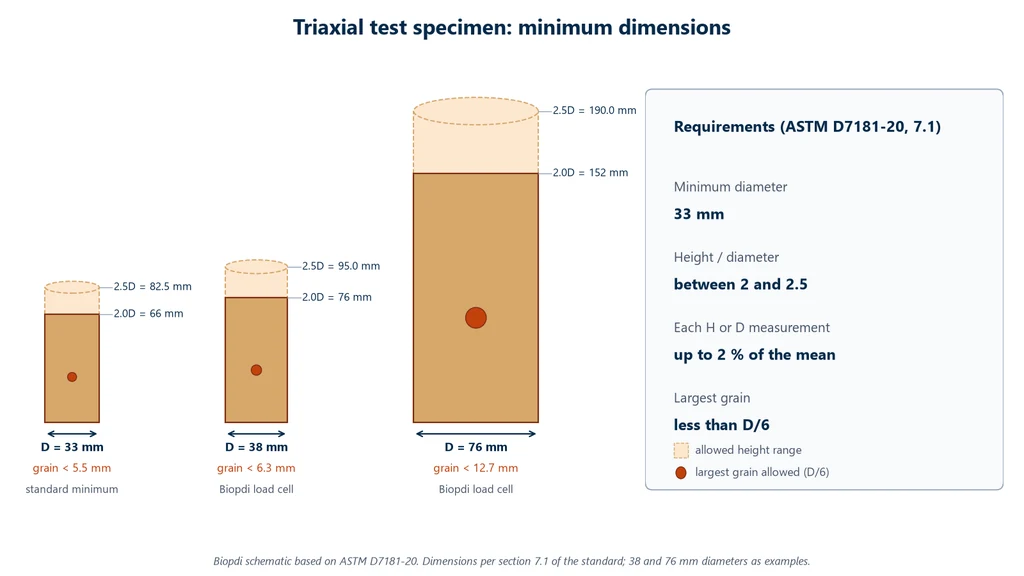
The maximum particle size allowed increases with specimen diameter. A 76 mm specimen accepts particles up to 12.7 mm, while a 38 mm specimen accepts particles only up to 6.3 mm. The diagram below shows the ASTM D7181-20 size limits to scale for the 33 mm minimum diameter and for the 38 mm and 76 mm diameters of Biopdi cells: the height range of 2 to 2.5 times the diameter and the largest particle allowed, which must be smaller than one sixth of the diameter.
Saturation, back pressure and the B parameter
The degree of saturation S is the ratio of the volume of water to the volume of voids in the soil, from 0 to 100%. CU and CD tests assume a saturated specimen, with S practically equal to 100%, because only then does the measured pore pressure represent the pore water. S cannot be measured directly in the cell, so saturation is achieved with back pressure and verified with the B parameter.
Back pressure is the pressure applied to the pore water through the drainage line. Raising the water pressure makes the residual air dissolve in it, just as gas stays dissolved in a sealed bottle. The cell pressure is raised at the same time and kept slightly above the back pressure. ASTM D4767 and D7181 use increments of 35 to 140 kPa and limit the difference between the two pressures to 35 kPa. This keeps the effective stress on the specimen small, positive and constant during saturation. Black and Lee (1973) showed that the back pressure required depends on the initial degree of saturation.
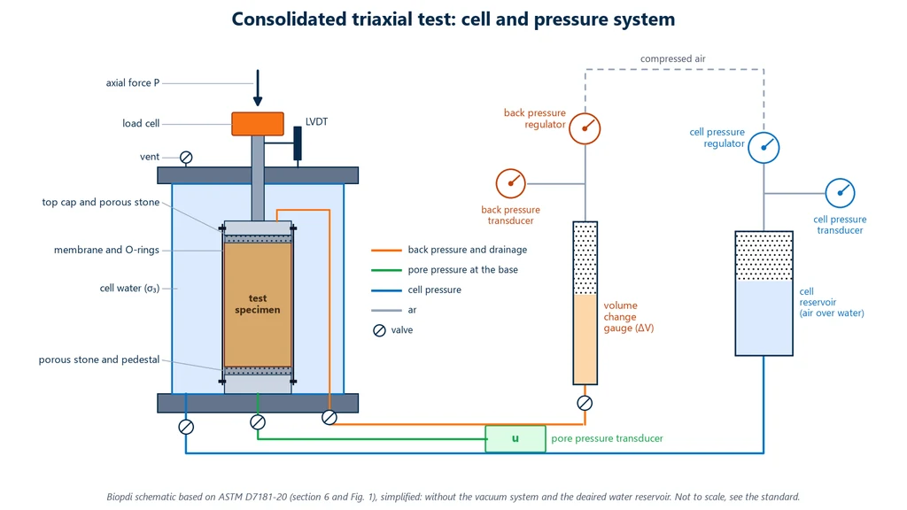
In the typical setup described in ASTM D7181-20, the cell reservoir, with its own regulator and transducer, applies σ3. The back pressure reaches the top of the specimen through a volume change device, which records the water that flows in during saturation and the water that flows out during consolidation and drained shearing. The pore pressure transducer reads u at the base. Cell pressure and back pressure come from separate regulators, so the difference between them can be kept small. The diagram below shows this setup and the path of each line to the cell.
To check saturation, the drainage is closed, the cell pressure is increased and the rise in pore pressure is measured. The ratio between the two is Skempton's B parameter (1954): B = Δu / Δσ3. B is 0 in dry soil, where the highly compressible pore air does not pass the increase on to the water. It approaches 1 in saturated soil, where the practically incompressible water carries the whole increase. ASTM D4767 considers the specimen saturated when B ≥ 0.95. Very stiff soils may not reach a B close to 1 even when saturated, because the soil skeleton takes part of the increase. In that case, ASTM D4767 and D7181 accept the specimen as saturated when B stops increasing with further back pressure increments.
Example: with back pressure at 300 kPa and cell pressure at 330 kPa, the drainage is closed and the cell pressure is raised by 70 kPa (the usual increment in ASTM D4767 and D7181) to 400 kPa. The pore pressure rises from 300 to 367 kPa. B = 67 / 70 = 0.96, which is above 0.95, so the specimen is saturated. If B were 0.90, the back pressure would have to be raised further, keeping the same difference between cell pressure and back pressure, and the check would be repeated. The software of the Biopdi static triaxial system has a dedicated screen for the B parameter check.
Consolidation and shearing rate
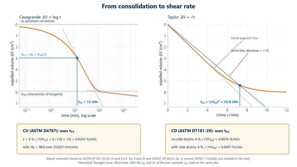
During consolidation, the specimen expels water until it reaches equilibrium with the new effective stress. This works as in the consolidation test (oedometer test), except that in the CIU test the pressure is equal in all directions. The time to reach 50% consolidation, t50, indicates how easily water flows through the soil and sets the shearing rate. In the CU test, the rate must be slow enough for pore pressure to equalize throughout the specimen, since it is measured only at the base. ASTM D4767 calculates the strain rate on the assumption that failure occurs after 4% strain:
ε̇ = 4% / (10 · t50)
If failure is expected before 4%, the estimated strain at failure is used in the formula instead. The formula and this caveat were checked against the 2004 edition of D4767. Check them against the current edition, D4767-11.
Example: with t50 = 12 min and a specimen height after consolidation of Hc = 98.0 mm, ε̇ = 4 / (10 × 12) = 0.0333% per minute. The piston speed is 0.000333 × 98.0 = 0.0327 mm/min. Reaching 15% strain takes 15 / 0.0333 = 450 min, or 7.5 h of shearing alone per specimen. The Biopdi static triaxial system runs at 0.001 to 30 mm/min, a range that covers this rate. For the CD test, ASTM D7181-20 uses t90, with the criterion that excess pore pressure must dissipate during shearing: ε̇ = 4% / (10·t90) without filter-paper side drains and ε̇ = 4% / (16·t90) with them. Both give even slower rates.
The diagram below shows how both times are read from the consolidation curve. t50 comes from Casagrande's construction on the plot of expelled volume against the logarithm of time, and t90 comes from Taylor's construction on the plot against the square root of time. The boxes apply each time to the formula in its standard, using the 12 min t50 from the example. Note that the CD rate, calculated from t90, is four to seven times slower than the CU rate.
Shearing and failure criterion
Shearing is usually strain-controlled. The load frame applies a constant rate and the force is whatever the soil resists, so the whole curve is recorded, including the post-peak portion. In stress-controlled loading, an older method, the force is increased in increments using weights or pressure, and the post-peak portion is not recorded.
During shearing, the load cell measures the axial force, the LVDT measures axial shortening, and the transducers measure the cell pressure and either the pore pressure (CU) or the volume of water flowing in and out (CD). Failure is defined by one of these common criteria: the maximum deviator stress, the maximum σ'1/σ'3 ratio or, when there is no peak, the deviator stress at 15% strain. The criterion used must be stated in the report, because the three can give different values for the same test.
Triaxial test calculations: formulas
Triaxial test calculations convert four readings (axial force, axial shortening, pressures and water volume) into stresses, and the stresses into the cohesion and friction angle of the soil. The table below gathers the formulas, which are explained one by one in the subsections:
| Quantity | Formula | Note |
|---|---|---|
| Axial strain | ε1 = ΔH / Hc | Hc = height after consolidation |
| Corrected area (undrained) | A = Ac / (1 − ε1) | Ac = area after consolidation; constant volume |
| Corrected area (drained) | A = (Vc − ΔV) / (Hc − ΔH) | ASTM D7181, with the measured volume change |
| Deviator stress | σd = P / A − Δσm | P = net piston force |
| Membrane correction | Δσm = 4 · Em · tm · ε1 / Dc | ASTM D4767 and D7181; apply if the effect exceeds 5% |
| Major principal stress | σ1 = σ3 + σd | σ3 = cell pressure |
| Effective stress | σ' = σ − u | Terzaghi |
| B parameter | B = Δu / Δσ3 | saturated if B ≥ 0.95 |
| Generated pore pressure (Skempton) | Δu = B · [Δσ3 + A · (Δσ1 − Δσ3)] | Skempton (1954) |
| A parameter at failure | Af = Δuf / σdf | with B ≈ 1 and constant σ3 |
| p and q coordinates | p' = (σ'1 + σ'3)/2; q = (σ1 − σ3)/2 | Lambe (MIT) diagram |
| Mohr-Coulomb envelope | τf = c' + σ' · tan φ' | kPa and degrees |
Area and membrane corrections
When compressed, the specimen shortens and bulges. In undrained shearing the volume is constant, so the area grows in the same proportion as the height decreases: A = Ac / (1 − ε1), where Ac is the area after consolidation. In the CD test, where the volume changes, ASTM D7181 calculates the area from the measured volume change: A = (Vc − ΔV) / (Hc − ΔH). Dividing the force by the initial area overestimates the stress. The latex membrane, stretched over the specimen, also helps carry the load; ASTM D4767 subtracts this effect with Δσm = 4·Em·tm·ε1/Dc, where Em is the membrane modulus, tm its thickness and Dc the diameter after consolidation. The correction matters most in soft soils, where the deviator stress is low, and the standards require it when the membrane effect exceeds 5% of the deviator stress.
Example: after consolidation, Ac = 19.00 cm², Hc = 98.0 mm and Dc = 49.18 mm. The membrane has tm = 0.3 mm and Em = 1,400 kPa (a typical value for latex, assumed for the example). At failure, ΔH = 7.84 mm and P = 238.7 N.
- ε1 = 7.84 / 98.0 = 0.080 (8.0%).
- A = 19.00 / (1 − 0.080) = 20.652 cm² = 0.0020652 m².
- P / A = 238.7 N / 0.0020652 m² = 115.6 kPa.
- Δσm = 4 × 1,400 × 0.3 × 0.080 / 49.18 = 2.7 kPa.
- σd = 115.6 − 2.7 = 112.9 kPa.
Without the area correction, the calculation would give 238.7 / 0.0019 = 125.6 kPa, about 9% above the corrected 115.6 kPa; without both corrections, 11% above the final result. The membrane effect here is 2.3%, below the 5% threshold at which the standards require the correction; it is included in the example only to show the calculation.
Mohr circles and strength envelope
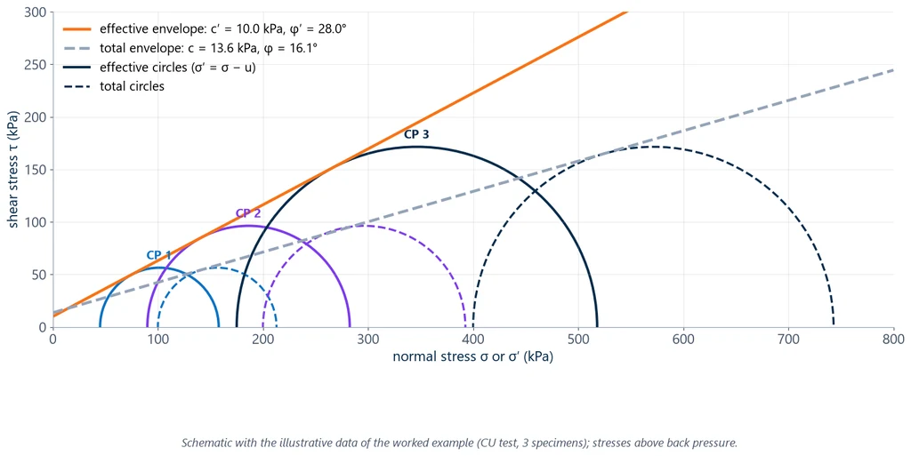
At failure, each specimen becomes a Mohr circle in the σ × τ plane: the center is at (σ1 + σ3)/2 and the radius is σd/2. The line tangent to the circles of the various specimens is the Mohr-Coulomb envelope, τf = c + σ·tan φ: the point where it crosses the vertical axis is the cohesion and its slope is the friction angle. In the CU test, the effective stress circles have the same radius as the total stress circles, because pore pressure acts equally in all directions and does not change the deviator stress; they are only shifted to the left by uf when the pore pressure is positive. By the same geometry, failure can also be written in terms of principal stresses: σ'1 = σ'3·tan²(45° + φ'/2) + 2c'·tan(45° + φ'/2).
Stress path in the p-q diagram
Drawing a full circle for every instant of the test would be unreadable. Lambe proposed representing each circle by its top point only, with coordinates p = (σ1 + σ3)/2 and q = (σ1 − σ3)/2, and following the path of this point throughout the test: the stress path. With constant σ3, the total stress path is a straight line at 45°. The effective path moves to the left of it when the pore pressure rises and to the right when it falls.
The failure points of several specimens line up on a straight line, the Kf line, q = a + p·tan α. It is converted into the Mohr-Coulomb parameters by sin φ = tan α and c = a / cos φ. Fitting a line through points is easier and more objective than drawing a common tangent to circles. The software of the Biopdi static triaxial test press plots the p × q and p' × q diagrams.
There is a second convention, the Cambridge one, with p' = (σ'1 + 2σ'3)/3 and q = σ1 − σ3, common in critical state models. The numbers differ from one to the other, so the report must state which was used; here we use Lambe's.
Skempton's A parameter
Skempton (1954) wrote the pore pressure generated in undrained loading as Δu = B·[Δσ3 + A·(Δσ1 − Δσ3)]. The B parameter measures the response to pressure applied equally in all directions; the A parameter measures the response to the deviator stress, that is, to shearing. In the CU test, with B ≈ 1 and constant σ3, the value at failure is Af = Δuf / σdf. A soil that tends to contract when sheared, such as normally consolidated clay, generates positive pore pressure and has a high Af; a soil that tends to dilate, such as heavily overconsolidated clay or dense sand, generates negative pore pressure and may have a negative Af.
Worked example: CU test with three specimens
Three specimens of the same clay were saturated with a back pressure of 300 kPa and consolidated under effective stresses of 100, 200 and 400 kPa. They were then sheared undrained, with pore pressure measurement. The data are illustrative, built for the example and checked by hand; all stresses are in kPa, above the back pressure. Specimen 1 is the one from the area correction example. At failure:
| Specimen | σ3 (kPa) | σdf (kPa) | Δuf (kPa) |
|---|---|---|---|
| 1 | 100 | 112.9 | 55 |
| 2 | 200 | 192.6 | 110 |
| 3 | 400 | 343.0 | 225 |
Step 1: principal stresses. σ1 = σ3 + σdf gives 212.9, 392.6 and 743.0 kPa. Subtracting the pore pressure, σ'3 = 100 − 55 = 45.0, 200 − 110 = 90.0 and 400 − 225 = 175.0 kPa. And σ'1 = 212.9 − 55 = 157.9, 392.6 − 110 = 282.6 and 743.0 − 225 = 518.0 kPa.
Step 2: p, p' and q coordinates. In total stresses, p = (212.9 + 100)/2 = 156.5, (392.6 + 200)/2 = 296.3 and (743.0 + 400)/2 = 571.5 kPa. In effective stresses, p' = p − Δuf = 101.5, 186.3 and 346.5 kPa. And q = σdf/2 = 56.5, 96.3 and 171.5 kPa, the same in both cases. The table summarizes the effective values:
| Specimen | σ'3 / σ'1 (kPa) | p' (kPa) | q (kPa) |
|---|---|---|---|
| 1 | 45.0 / 157.9 | 101.5 | 56.5 |
| 2 | 90.0 / 282.6 | 186.3 | 96.3 |
| 3 | 175.0 / 518.0 | 346.5 | 171.5 |
Step 3: effective envelope. Using the points of specimens 1 and 3, tan α' = (171.5 − 56.5) / (346.5 − 101.5) = 115.0 / 245.0 = 0.4694. So sin φ' = 0.4694 and φ' = 28.0°. The intercept is a' = 56.5 − 0.4694 × 101.5 = 8.8 kPa, and c' = 8.8 / cos 28.0° = 8.8 / 0.883 = 10.0 kPa. Check with specimen 2: 8.8 + 0.4694 × 186.3 = 96.3 kPa, equal to the measured q. Linear regression through the three points gives the same result.
Step 4: total envelope. tan α = (171.5 − 56.5) / (571.5 − 156.5) = 115.0 / 415.0 = 0.2771, so φ = 16.1°; a = 56.5 − 0.2771 × 156.5 = 13.1 kPa and c = 13.1 / cos 16.1° = 13.6 kPa. Specimen 2 falls 1 kPa below the line (95.2 versus 96.3 kPa), which is normal scatter; in practice the line is fitted by regression through the three points.
Step 5: Mohr-Coulomb check. With φ' = 28° and c' = 10 kPa, tan(45° + 14°) = tan 59° = 1.664 and tan² 59° = 2.770. For specimen 1: σ'1 = 45.0 × 2.770 + 2 × 10 × 1.664 = 124.6 + 33.3 = 157.9 kPa, equal to the measured value.
Step 6: A parameter. Af = Δuf / σdf = 55/112.9 = 0.49, 110/192.6 = 0.57 and 225/343.0 = 0.66.
The Mohr circles below show the result: the three total stress circles (dashed) are tangent to the lower total envelope, and the three effective stress circles, with the same radius and shifted to the left by the pore pressure, are tangent to the steeper effective envelope.
The same example is cleaner in the p-q diagram: each specimen starts on the horizontal axis at its consolidation stress, the total stress path rises at 45° and the effective failure point lies to the left of it, on the Kf' line. The chart shows only the start and the failure point in effective stresses; in a real test the software records the path point by point.
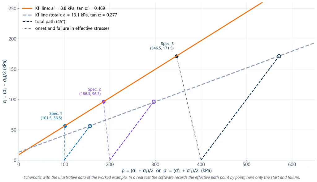
Interpreting the result: Af between 0.49 and 0.66, with positive pore pressure, indicates contractive behavior, typical of normally consolidated to lightly overconsolidated clay. The total φ of 16° is much lower than the φ' of 28°, because the positive pore pressure reduced the effective stress at failure. That is why the total envelope from a CU test is not suitable for long-term analysis, once the pore pressure has dissipated.
Example: UU test and unconfined compression
Three specimens of saturated clay were tested in UU with σ3 = 50, 100 and 150 kPa and failed at σdf = 84, 85 and 83 kPa. The Mohr circles all have a radius of about 42 kPa, and the envelope is horizontal: su ≈ 42 kPa and φu = 0. An unconfined compression test on the same soil would give qu ≈ 84 kPa, and su = qu/2 = 42 kPa, provided the soil does not lose water during the test and falls within the scope of NBR 12770 (the Brazilian standard for unconfined compression of cohesive soils).
Exercise: UU with area correction
Problem. A saturated clay specimen, with D = 38 mm and H = 76 mm, is tested in UU with σ3 = 150 kPa. At failure, the shortening is ΔH = 6.08 mm and the net piston force is P = 0.25 kN. Calculate σdf and su.
- ε1 = 6.08 / 76 = 0.080 (8.0%).
- A0 = π × 0.038² / 4 = 1.1341 × 10⁻³ m².
- A = A0 / (1 − ε1) = 1.1341 × 10⁻³ / 0.92 = 1.2328 × 10⁻³ m².
- σdf = 0.25 kN / 1.2328 × 10⁻³ m² = 202.8 kPa, and σ1f = 150 + 202.8 = 352.8 kPa.
- su = σdf / 2 = 101.4 kPa.
Answer: su ≈ 101 kPa. With the initial area, σdf would be 0.25 / 1.1341 × 10⁻³ = 220.4 kPa, 8.7% higher. The membrane correction, with the values from the previous example, would be about 3.5 kPa, 1.7% of σdf, below the 5% threshold at which it is required.
Exercise: checking the B parameter
Problem. During saturation, with the back pressure at 400 kPa and the cell at 430 kPa, the drainage is closed and the cell pressure is raised by 70 kPa, to 500 kPa. Evaluate two cases: (a) the pore pressure rises by 68 kPa; (b) it rises by 63 kPa.
- (a) B = 68 / 70 = 0.97, greater than 0.95: the specimen is saturated and can proceed to consolidation.
- (b) B = 63 / 70 = 0.90, less than 0.95: return the cell pressure to its previous value, raise the back pressure while keeping the 30 kPa difference, wait and measure B again.
- If, in a stiff soil, B stops increasing with further back pressure increments, ASTM D4767 and D7181 accept the specimen as saturated even below 0.95.
Exercise: CD with two specimens
Problem. Two specimens of a clayey sand were tested in CD. The first, with σ'3 = 100 kPa, failed at σ'1f = 300 kPa; the second, with σ'3 = 200 kPa, at σ'1f = 580 kPa. Calculate c' and φ'.
- From the Mohr-Coulomb relationship, σ'1 = σ'3 · Kp + 2c' · √Kp, with Kp = tan²(45° + φ'/2). Subtracting the two equations: 580 − 300 = (200 − 100) · Kp, so Kp = 2.80.
- √Kp = tan(45° + φ'/2) = 1.6733, so 45° + φ'/2 = 59.14° and φ' ≈ 28.3°.
- 300 = 100 × 2.80 + 2c' × 1.6733, so c' = 20 / 3.3466 = 6.0 kPa.
- Check in the p'-q diagram: the failure points are (200, 100) and (390, 190) kPa. tan α = 90 / 190 = 0.4737 = sin φ', so φ' = 28.3°; a = 100 − 0.4737 × 200 = 5.26 kPa and c' = 5.26 / cos 28.3° = 6.0 kPa.
Answer: φ' ≈ 28.3° and c' ≈ 6.0 kPa. With only two specimens the line passes exactly through both points and there is no way to assess the scatter; the exercise is for practicing the calculation, and a real test uses at least three.
How to interpret triaxial test results
The values of c and φ only make sense together with the curves that produced them. The questions below cover what the engineer needs to read in the report before using the parameters.
What does the shape of the deviator stress vs. strain curve indicate?
A sharp peak followed by a drop indicates a soil that loses strength after failure: overconsolidated clay or dense sand, usually with a well-defined failure plane. A curve that rises continuously or forms a plateau, with the specimen bulging, indicates normally consolidated clay or loose sand. When there is no peak, failure is taken at 15% strain, and this criterion must be stated.
Why does pore pressure rise in some soils and fall in others?
Because the soil tends to change volume when sheared and, without drainage, the water prevents it. A contractive soil tends to compress: the water is compressed and the pore pressure rises. A dilatant soil tends to expand: the water is put in tension and the pore pressure drops, and may become negative. In the CD test, where water can flow out and in, the same behavior appears as a volume decrease in loose soil and as expansion, after the initial compression, in dense soil.
Which envelope to use: total or effective?
The effective envelope (c', φ') applies to long-term analyses and whenever the field pore pressure is known or estimated. The total envelope, and especially the su from the UU test, applies to rapid loading, where the field pore pressure is the same as that generated in the test. Using the CU total envelope in a long-term analysis, or the φu = 0 from the UU test for stability after years, is one of the most common mistakes.
Is the c' obtained true cohesion?
Not always. In normally consolidated clay, the true effective cohesion is practically zero, and a small c' is usually an artifact of the straight line fitted to the points over a limited stress range. In design, it is prudent to check the sensitivity of the analysis to c' before relying on it.
What does the value of Af say about the soil?
A high, positive Af, close to 1, indicates a strongly contractive soil, such as soft normally consolidated clay. A low Af indicates overconsolidation, and a negative Af indicates a dilatant soil, such as heavily overconsolidated clay. The parameter helps estimate the pore pressure a structure will generate in the field.
When does the UU result apply to design?
When the soil is saturated and the structure loads it faster than the water can drain, as in an embankment on soft clay at the end of construction. In unsaturated soil, the UU envelope is curved, because the air in the pores compresses, and the theory of the B and A parameters does not apply without adjustments.
Dynamic triaxial test and resilient modulus
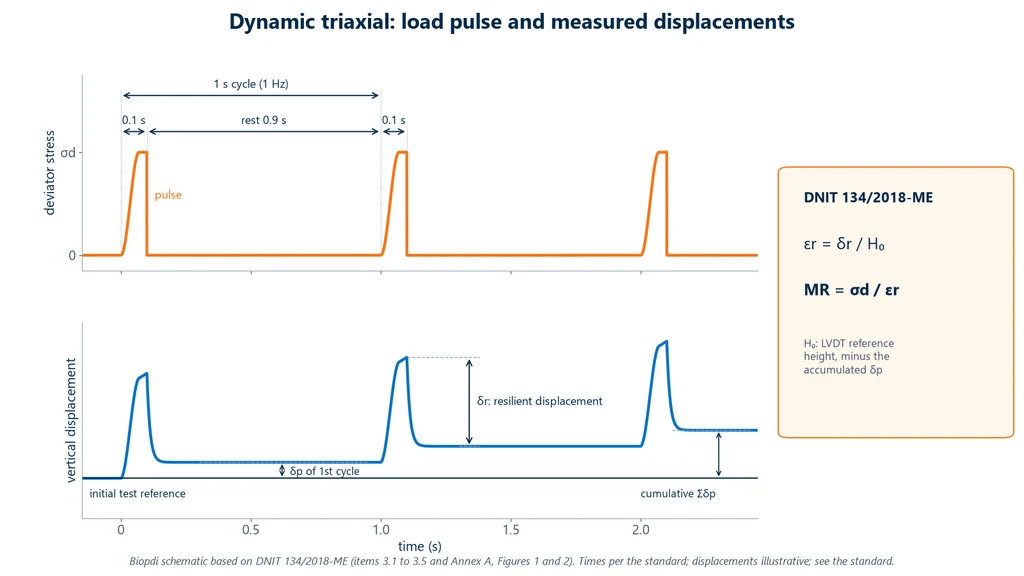
The UU, CU and CD tests are static: the load increases continuously, at constant rate, until failure. In the dynamic triaxial test, or repeated load triaxial test, the specimen receives short pulses of deviator stress under confining pressure, to reproduce the passage of vehicle wheels over the pavement. The test does not take the soil to failure. It measures the deformation the soil recovers at each pulse, which gives the resilient modulus, MR = σd / εr, per DNIT 134/2018-ME (the test method of DNIT, Brazil's federal highway agency), and the deformation that accumulates over at least 150,000 load cycles, the permanent deformation, per DNIT 179/2018-IE. The complete procedure, with the stress pairs, the behavior models and exercises, is in the article on resilient modulus. For pavement design by the traditional empirical method, see also the CBR test.
The diagram below shows the loading standardized by DNIT 134/2018-ME and what the LVDT records. Each cycle has a 0.1 s deviator stress pulse followed by 0.9 s of rest, at a frequency of 1 Hz. At each pulse, the specimen deflects and recovers the portion δr, the resilient displacement, while the permanent portion δp accumulates. The resilient modulus is obtained from δr, divided by the reference height H0.
Common mistakes in the triaxial test
Most bad results come from a few faults, almost all in saturation, shearing rate or corrections:
- Incomplete saturation (B < 0.95): the air in the pores absorbs part of the pressure increment, the measured pore pressure is lower than the real one, and the effective stress and effective strength are overestimated.
- High rate in the CU test: the pore pressure does not equalize along the specimen, and the value read at the base does not represent the center. The rate must be derived from t50.
- CD test run too fast: it generates pore pressure and the test is no longer drained, without the result showing it.
- Forgetting the area correction: in the example in this guide, it overestimates the deviator stress by about 9% at 8% strain.
- Ignoring the membrane correction: of little relevance in stiff soil, significant in soft soil, with low deviator stress.
- Using the UU test or the CU total envelope in a long-term analysis.
- Confusing the acronyms: CIU is the isotropic case of the CU test, not a different test; and the UC test, with σ3 = 0, is not a triaxial test.
- Presenting NBR 12770 as a triaxial test standard: this Brazilian standard covers unconfined compression.
- Drawing the envelope with one or two specimens: the practical minimum is three, at different confining pressures, the number ASTM D4767 and D7181 indicate as usual and the minimum required by ISO 17892-9.
- Reading the c' of normally consolidated clay as true cohesion.
- Citing the standard without the edition: ASTM D2850, for example, is already at edition D2850-26, and editions change requirements.
Equipment for the triaxial test
The static triaxial test needs five parts: a load frame that compresses the specimen at a constant and very low rate, a triaxial cell that confines it, a pressurization system that applies the cell pressure and back pressure and measures the water volume, a load cell for the axial force and an LVDT for the axial shortening. Biopdi manufactures the triaxial testing system in three configurations: static, dynamic, and static and dynamic.
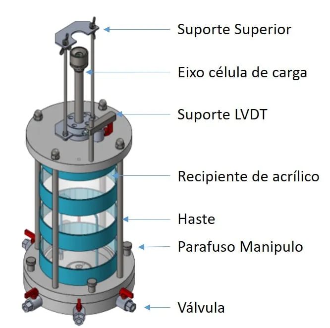
The triaxial cell has an acrylic chamber between an aluminum base and top cap, tie rods, an LVDT bracket and the loading ram that transfers the load to the top cap. The ball valves on the base make the cell pressure, back pressure and pore pressure connections. In the Biopdi version, the cell accepts specimens 38 and 76 mm in diameter and works at 1.0, 1.6 or 3.4 MPa, depending on the model, with pedestal, top platen, porous stones and latex membranes. The image below identifies each part:
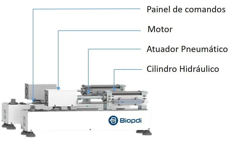
The pressurization system ensures controlled water pressure and volume in the cell and in the specimen. In Biopdi's basic model, the pressure is pneumatic and adjusted manually by the operator. In the automatic model, the 1,600 kPa water pressure controller uses a motor and a lead screw to drive the piston of a 150 cm³ hydraulic cylinder: the pressure is programmed on the panel, with 0.1 kPa resolution, and maintained by the equipment, and pressure, pore pressure and volume transducers, with 0.5% accuracy, measure the cell pressure, back pressure, pore pressure and the volume change of the specimen. The photo shows the system with the control panel, the motor and the hydraulic cylinder:
The panel below shows the static triaxial testing system, the role of each part in the test and the accessories:
The static triaxial testing system in the triaxial test
Biopdi's static triaxial testing system is electromechanical, servo-controlled, twin-column, with a ball screw drive, a capacity of 50 kN (11,240 lbf), a speed of 0.001 to 30 mm/min, 100 mm of stroke and position read by a 0.001 mm encoder. Each part has a function in the test:
- Electromechanical load frame compresses the specimen at constant rate, from 0.001 to 30 mm/min
- Triaxial cell acrylic and aluminum, 38 and 76 mm specimens, 1.0 to 3.4 MPa depending on the model
- Pressurization cell pressure, back pressure, pore pressure and volume change; up to 1,600 kPa in the automatic model
- Load cell 50 kN, interchangeable, submersible or non-submersible
- LVDT 50 mm, 0.01 mm resolution, measures the axial shortening
- Software UC, UU, CU and CD, B parameter, Mohr circles and stress paths
Accessories for the triaxial test
The accessories below are mounted on the same load frame, depending on the type of test:
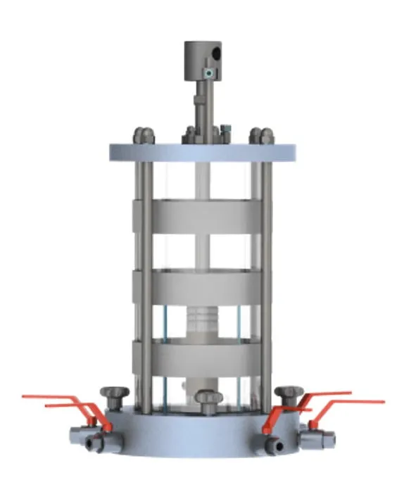 Static triaxial cellacrylic and aluminum
 Pressurization systempressure and volume, up to 1,600 kPa
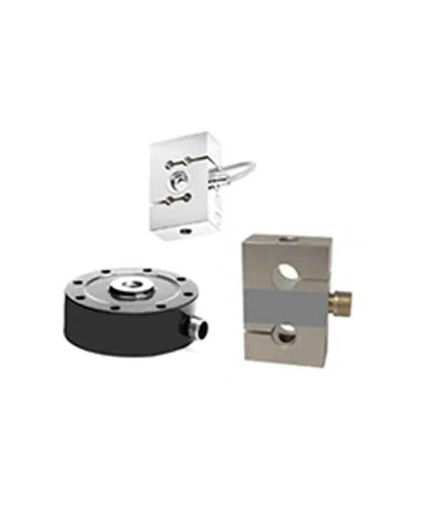 Load cellsubmersible and non-submersible
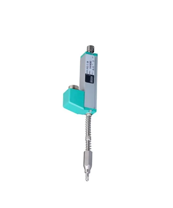 LVDTsubmersible and non-submersible
The static system is offered in two versions: the basic static triaxial testing system, with manually adjusted pneumatic pressurization, and the automatic static triaxial testing system, with the 1,600 kPa water pressure controller. In the software, the configuration includes the B parameter check, the consolidation curve with the suggested shearing rate, the plots of deviator stress, pore pressure and volume change against strain, the p × q and p' × q diagrams and the Mohr circles. The minimum speed of 0.001 mm/min meets the slow shearing of CU and CD tests on clays, and the 50 kN capacity is more than enough for 76 mm specimens: in the example in this guide, the highest force at failure does not reach 1 kN on a 49 mm specimen. For the repeated load triaxial test, the dynamic triaxial testing system is pneumatic, 20 kN, with a frequency of 1 to 5 Hz. Biopdi also manufactures the direct shear apparatus and the consolidation apparatus. To configure the equipment for your laboratory, request a quote or talk to one of our specialists.
Triaxial testing system videos
The videos below show the static and the dynamic triaxial testing systems in operation, including a dynamic test on soil samples.
Triaxial test standards
The ASTM and ISO standards below were checked on October 1, 2026 on the official pages (store.astm.org and iso.org), with ISO 17892-9 rechecked on October 5, 2026, and the DNIT standards in the DNIT standards collection (DNIT is Brazil's federal highway agency). There is no specific ABNT (Brazilian) standard for the triaxial test; ABNT NBR 12770:2022 covers only unconfined compression, and its status should be checked in the ABNT catalog.
| Standard | Scope | Current edition |
|---|---|---|
| ASTM D2850 | UU triaxial test on cohesive soils | D2850-26 |
| ASTM D4767 | CU triaxial test on cohesive soils, with B ≥ 0.95 and area and membrane corrections | D4767-11, reapproved 2020 |
| ASTM D7181 | CD triaxial test on soils | D7181-20 |
| ASTM D2166/D2166M | unconfined compressive strength of cohesive soil (UC) | D2166/D2166M-24 |
| ISO 17892-8 | unconsolidated undrained triaxial test (UU) | 2018, confirmed 2023 |
| ISO 17892-9 | consolidated triaxial tests (CU and CD) on saturated soils, with isotropic or anisotropic consolidation and effective stress paths; requires at least three tests | 2018, confirmed 2023 |
| ABNT NBR 12770:2022 | unconfined compression of cohesive soil | check the status in the ABNT catalog |
| DNIT 134-ME | resilient modulus of soils (repeated load triaxial test) | 2018 |
| DNIT 179-IE | permanent deformation of soils | 2018 |
The scientific references cited are Skempton, A. W. (1954), "The pore-pressure coefficients A and B", Géotechnique 4(4), pp. 143-147; Black, D. K. and Lee, K. L. (1973), "Saturating laboratory samples by back pressure", Journal of the Soil Mechanics and Foundations Division, ASCE, vol. 99, no. SM1, pp. 75-93; and Bishop, A. W. and Henkel, D. J. (1957), The Measurement of Soil Properties in the Triaxial Test, which systematized the method.
Other tests and technical references
CBR test and the California Bearing Ratio
CBR test (California Bearing Ratio): NBR 9895:2025 and DNIT 172 standards, procedure, formula with 6.9 and 10.35 MPa, worked example and CBR by layer.
Direct shear test: ASTM D3080 standard, step-by-step procedure and how to calculate c' and φ'
The direct shear test measures soil shear strength and gives the cohesion c' and friction angle φ'. ASTM D3080-23, step by step, with a worked example.
Resilient modulus (MR): what it is, how to calculate it and the repeated load test per Brazilian standards DNIT 134 and 135/2018
Resilient modulus (MR) is repeated deviator stress divided by recoverable strain in soils, aggregates and asphalt: MR = σd/εr, in MPa (DNIT 134, 135).
Shear strength of soil: Mohr-Coulomb, cohesion and friction angle
Shear strength of soil: effective stress, the Mohr-Coulomb criterion, cohesion and friction angle, with typical values and 5 worked examples.
Frequently asked questions
What is the triaxial test?
The triaxial test, or triaxial compression test, is a laboratory test that measures the shear strength and deformability of soils, and also of rocks, by compressing to failure a cylindrical specimen enclosed in a membrane and confined by pressurized water inside a cell. By controlling drainage and measuring pore pressure, it provides cohesion and friction angle in terms of total or effective stresses, as well as the stress-strain curve. It applies to sandy, clayey and silty soils, whether undisturbed or compacted. The name comes from the three principal stresses acting on the specimen, the vertical σ1 and the two horizontal σ2 = σ3; since the horizontal stresses are equal, the conventional test is axisymmetric, and the true triaxial test, with all three different, is research equipment.
What are the types of triaxial test and their applications?
There are three main types, each with its own standard: unconsolidated undrained (UU), per ASTM D2850; consolidated undrained (CU), per ASTM D4767; and consolidated drained (CD), per ASTM D7181. The unconfined compression test (UC), per ASTM D2166, is the case without confinement. The UU test addresses short-term problems, such as an embankment on soft clay at the end of construction; the CU and CD tests provide the effective parameters for the long term, in slopes, dams and retaining structures. Applications are in geotechnical engineering and civil construction: foundations, earthworks and pavements.
How is the soil triaxial test performed?
A cylindrical specimen is trimmed, with a height of 2 to 2.5 times its diameter, enclosed in a latex membrane between two porous stones, and mounted in the water-filled triaxial cell. In the CU and CD tests, it is saturated by back pressure until B ≥ 0.95 and consolidated under the chosen confining stress. The load frame then compresses it at a constant rate until failure, with drainage open or closed depending on the test type, while measuring force, axial shortening and pore pressure or volume change. The test is usually repeated on three specimens.
What are the differences between the triaxial test and the direct shear test?
The triaxial test controls drainage, measures pore pressure and does not impose the failure plane; the direct shear test is simpler and cheaper, but does none of these three things. There are four practical differences. Drainage: the direct shear test is in practice performed under drained conditions, while the triaxial test can be run drained or undrained. Pore pressure: the direct shear test does not measure it, the triaxial test does. Saturation: in the direct shear test it comes from filling the shear box with water; in the triaxial test, from adjustable back pressure inside the cell, verified by the B parameter. Failure plane: the direct shear test forces failure along the horizontal plane of the box, while in the triaxial test the specimen fails along its weakest plane, as happens in the field. This is why the triaxial test is the laboratory test that comes closest to real soil conditions, and the only one of the two that provides effective parameters in an undrained test.
What is a static triaxial test?
It is the triaxial test in which the axial load increases continuously, at a constant strain rate, until failure, without cycles: the UU, CU and CD tests are static. The dynamic triaxial test, by contrast, applies repeated pulses of deviator stress without failing the soil and measures the resilient modulus per DNIT 134/2018-ME (a standard of DNIT, Brazil's national transportation infrastructure department) and permanent deformation per DNIT 179/2018-IE.
What is the triaxial test used for?
To determine the mechanical properties of soils and rocks: shear strength, expressed by cohesion and friction angle, stress-strain behavior, pore pressure generation and volume change during shearing. These parameters feed stability and bearing capacity calculations.
What is axial compression?
It is the load applied along the axis of the specimen. In the triaxial test, the axial stress is σ1 = σ3 + σd, where σd = P / A is the piston force divided by the corrected area; in the unconfined compression test, σ3 = 0 and the axial stress is simply P / A. The principle is covered in the article on the compression test.
What is the standard for the triaxial test?
There is no ABNT (Brazilian) standard for the triaxial test. The standards used are ASTM D2850-26 (UU), ASTM D4767-11, reapproved in 2020 (CU), ASTM D7181-20 (CD), and ISO 17892-8 and 17892-9, both from 2018. ABNT NBR 12770:2022 (the Brazilian standard for unconfined compression of cohesive soils) covers only the unconfined compression test; check its status in the ABNT catalog. The repeated-load triaxial test for pavements follows DNIT 134/2018-ME.
What is the CIU triaxial test?
It is the consolidated undrained (CU) test with isotropic consolidation, that is, under equal pressure in all directions, and with pore pressure measurement during shearing. It provides both total and effective parameters in a single test. When consolidation is anisotropic, the test is called CAU.
What is the degree of saturation of soil?
The degree of saturation S is the fraction of the void volume occupied by water: 0% in dry soil and 100% in saturated soil. In CU and CD triaxial tests the specimen must be saturated, with a degree of saturation practically equal to 100%, that is, with all soil voids filled with water. Since the degree of saturation is not measured directly in the cell, it is checked by Skempton's B parameter: with drainage closed, the cell pressure is increased and the rise in pore pressure is measured. B = Δu / Δσ3, and ASTM D4767 considers the specimen saturated when B ≥ 0.95. To get there, back pressure is used, which raises the pore water pressure and dissolves the remaining air into it, while the cell pressure is raised along with it so that the effective stress does not change during saturation.
How many specimens are needed?
Usually three, tested at different confining stresses, to draw the Mohr-Coulomb failure envelope and obtain cohesion and friction angle. ASTM D4767 and D7181 refer to three as the usual number, and ISO 17892-9 is more explicit: it requires a set of at least three related tests to determine the strength parameters. With two points, any straight line passes through them, and there is no way to assess the scatter.
How long does a triaxial test take?
The UU test is the shortest, because it has no saturation or consolidation stage. The CU and CD tests depend on the soil's permeability, since the shearing rate is derived from the consolidation time: they take hours in sands and, in clayey soils, can take from days to weeks per specimen, as ASTM D7181 warns. In the example in this guide, with a t50 of 12 min, the shearing stage alone of one CU specimen takes 7.5 h.