
ASTM D695, Standard Test Method for Compressive Properties of Rigid Plastics, is the ASTM method that measures the compressive strength, compressive yield and compressive modulus of rigid plastics, reinforced or unreinforced, by compressing a 12.7 × 12.7 × 25.4 mm prism at 1.3 ± 0.3 mm/min between parallel surfaces. The current edition, checked on October 1, 2026, is ASTM D695-26. The results are reported as compressive strength, compressive yield strength and compressive modulus. For strength, a 12.7 mm diameter cylinder of the same height is also allowed, and the modulus specimen is 50.8 mm high. In every case, compressive strength is the maximum force in the test divided by the minimum original cross-sectional area: σc = Fmax / A0,min.
In short:
- Scope: rigid plastics, including high-modulus composites up to 41,370 MPa; oriented continuous-fiber composites go to ASTM D3410/D3410M or D6641/D6641M.
- Specimen: length twice the width for strength; slenderness ratio of 11 to 16 for modulus and offset yield.
- Thin material: below 3.2 mm, a dedicated specimen mounted in a support jig that prevents buckling.
- It is not ISO 604: ASTM states that the two are equivalent, but specimen, speed and modulus calculation differ, and the results are not interchangeable.
The standard is a paid document sold by ASTM. This guide explains in our own words what it requires, for those who will apply it, audit a test report or buy the equipment, and quotes only the essential numerical requirements, with the source of each.
What ASTM D695 covers and which edition is current
The compression test applies an increasing axial force to a specimen that shortens it, and records force and deformation up to fracture or up to a defined limit. The principle, the curve of each material family and the choice between a press and a universal testing machine are explained in that article. In D695, the force enters only through the ends of the specimen, without grips, a principle the composites literature calls end-loading compression. Here the subject is what D695 adds for plastics: the geometry, the speed, how deformation is measured, the corrections and what to report when the material does not fracture.
D695 was first approved in 1942 and is maintained by Subcommittee D20.10 (mechanical properties) of Committee D20 on plastics. In the ASTM store, checked on September 30, 2026 and again on October 1, 2026, the active edition is D695-26, with 8 pages, in volume 08.01 of the Book of Standards. The page history lists editions D695-96, -02, -02a, -08, -10, -15, -23 and -26. Pages that still treat D695-15 or D695-02 as current are out of date.
The published scope of D695-26 is the same as in previous editions: unreinforced and reinforced rigid plastics, including high-modulus composites, loaded in compression at low, uniform rates, in specimens of standard shape, up to a modulus of 41,370 MPa (6,000,000 psi). The following are excluded:
- Composites with oriented, continuous, discontinuous or cross-ply reinforcement: D695 itself refers them to ASTM D3410/D3410M, which loads the specimen through shear at the grips, or to D6641/D6641M, which combines end loading and shear loading.
- Plastics that are not rigid, such as flexible foams and elastomers, which have their own standards.
- Packaging and finished parts: ASTM D642, which shows up alongside it in searches, tests boxes, drums and unit loads in compression, not the material.
Two rules of use appear at the very start of the text. The first is precedence: if there is an ASTM material specification, its preparation, conditioning, dimensions and parameters take precedence over those of D695, which serves as the default when there is no specification (the list is in Table 1 of ASTM D4000). The second is applicability: the test is suitable for research, quality control and material acceptance, but does not apply directly to design under load scales and times very different from those of the test.
About the edition: the numerical requirements in this guide were checked against the full text of D695-15. The ASTM store does not publish the summary of changes for editions -23 and -26, and the scope shown for -26 has not changed; anyone auditing a laboratory should confirm the numbers in the copy of D695-26.
Test specimens: prism, cylinder and special cases
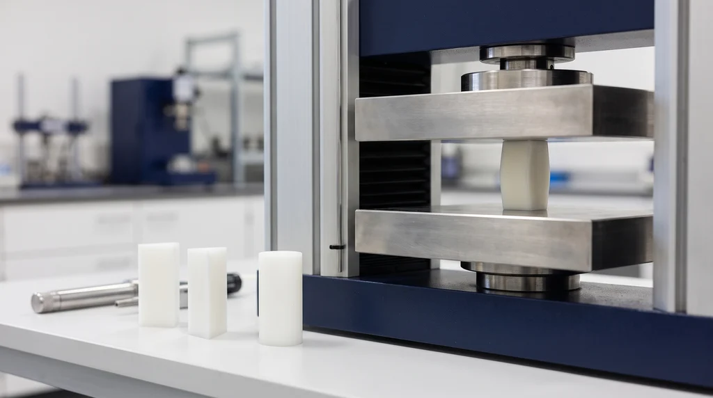
The D695 specimen is a block with flat, parallel faces, squeezed between two loading surfaces. It can be machined from sheet, plate, rod or tube, or compression- or injection-molded. The shape depends on what is to be measured: strength calls for a short block that crushes before it buckles; modulus calls for a taller block, with room for the instrument that reads the deformation. In the photo, a rigid plastic prism between the compression platens, already slightly barreled in the middle; beside it, prisms and a cylinder not yet tested, the specimen shapes of the standard.
Strength and modulus: the slenderness ratio
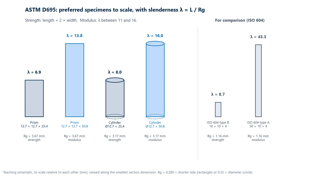
To measure strength, D695 calls for a right cylinder or prism with a length twice its width or diameter. The preferred sizes are the 12.7 × 12.7 × 25.4 mm prism and the 12.7 mm diameter by 25.4 mm cylinder. To measure modulus and offset yield (the stress read with a line parallel to the straight portion of the curve, explained in the calculation section), the criterion changes to the slenderness ratio, which must be between 11 and 16; the preferred specimens are then 50.8 mm high.
The slenderness ratio is the length divided by the least radius of gyration of the cross section, λ = L / Rg. The radius of gyration measures how the cross-sectional area is distributed around the bending axis, and a column's resistance to buckling depends on it: the higher λ, the easier it is for the part to bow sideways instead of shortening. The standard gives the radius of gyration for three sections:
- Rectangle: Rg = 0.289 × smaller side. For the 12.7 mm prism, Rg = 3.67 mm.
- Circle: Rg = 0.25 × diameter. For the 12.7 mm cylinder, Rg = 3.175 mm.
- Tube: Rg = √(D² + d²) / 4, where D is the outside diameter and d the inside diameter.
With these values, the 25.4 mm prism has λ = 25.4 / 3.67 = 6.9 and the 50.8 mm prism λ = 13.8, within the modulus range. For the cylinder, 25.4 mm gives λ = 8.0 and 50.8 mm gives λ = 16.0, exactly the upper limit. The strength specimen falls outside the 11 to 16 range on purpose: being short, it does not buckle, but it also leaves no room for the compressometer, the extensometer attached to the specimen that reads the shortening. The diagram below draws the four preferred specimens at the same scale, with the slenderness ratio of each, and places beside them the two ISO 604 specimens, the subject of a later section:
Rods, tubes, laminates and reinforced materials
When the material comes in another form, D695 adapts the specimen while keeping the same two rules: twice the width for strength and a slenderness ratio of 11 to 16 for modulus. The table summarizes the cases, paraphrased from D695-15:
| Material form | Strength | Modulus and offset |
|---|---|---|
| Rod | rod diameter, length of 2 diameters | rod diameter, slenderness ratio of 11 to 16 |
| Tube (wall ≥ 1 mm, inside diameter ≥ 6.4 mm, outside diameter ≤ 50.8 mm) | tube diameter, 25.4 mm long | tube diameter, slenderness ratio of 11 to 16 |
| High-pressure laminate thinner than 25.4 mm | stack of 12.7 mm squares up to about 25.4 mm | stack up to a slenderness ratio of 11 to 16 |
| Reinforced, 3.2 to 6.4 mm | prism 12.7 mm × thickness × 12.7 mm | slenderness ratio of 11 to 16 |
| Reinforced, over 6.4 mm | standard prism or cylinder | standard prism or cylinder |
| Syntactic foam | 25.4 × 50.8 mm cylinder | the same cylinder |
If the rod or tube is too large for the machine to break, a standard specimen is machined from the center of the rod or from the tube wall. For a tube, the same 25.4 mm piece serves for the transverse crushing load, with the diameter becoming the height. For reinforced material 3.2 to 6.4 mm thick, the prism may be shortened if it buckles, and if it fails by delamination rather than along a shear plane, the material moves to the thin specimen described in the next section.
Preparation, measurement and number of specimens
Machining is the critical part. The side faces must come out smooth, and the ends smooth, flat, parallel, with sharp edges and perpendicular to the specimen axis within 0.025 mm. A tilted end makes the platen touch a corner first, which concentrates the load, lengthens the start of the curve and lowers the strength. ISO 604 recommends facing the ends on a lathe or milling machine, and the recommendation applies to D695.
Each specimen has its width and thickness, or its diameter, measured to 0.025 mm at several points along its length, with a micrometer reading to 0.01 mm. The area used in the calculations is the minimum measured cross section, not the average or the nominal one. The minimum is five specimens per sample of isotropic material; for material suspected of anisotropy it is ten, five with the axis parallel and five normal to the suspected direction. A specimen that fails at an obvious flaw is discarded and replaced, unless the flaw is the variable under study. General precautions for sampling and machining specimens are in the article on the test specimen.
Thin specimen and anti-buckling support jig
The D695 anti-buckling support jig is a pair of steel plates, tightened by screws, that encloses the wide faces of a thin specimen and prevents it from bowing sideways without carrying the load, which still enters through the ends. It exists because sheets and laminates less than 3.2 mm thick do not yield a prism that can resist without buckling. For them, and also when the modulus test calls for a length that the slenderness ratio does not allow, D695 uses a dedicated specimen, drawn in the standard with wider end tabs and a narrower central section, about 79 mm long and 19 mm wide at the ends, mounted in the jig.
Mounting follows three rules, each backed by an interlaboratory study cited in the standard:
- Position: the specimen sits flush with the base of the jig and centered. The comparison between flush and centered mounting showed no effect on strength; the standard sets flush mounting for convenience.
- Tightening: the nuts or screws are tightened finger-tight only. Tighter clamping creates friction between the plates and the specimen, which then carry part of the force; finger tightening gave reproducible results.
- Modulus: a compressometer applied to the edges of the specimen mounted in the jig gave relatively satisfactory modulus measurements.
The assembly goes into the compression fixture like an ordinary specimen. The exact dimensions of the specimen and the jig are in the figures of the standard.
For advanced composites, the aerospace industry derived versions of D695 in which the jig is rigidly attached to the compression fixture, known as modified D695: Boeing BSS 7260 (types III and IV), SACMA SRM 1R-94 and EN 2850 method B. Instead of the tapered specimen, they use two straight specimens: one without end tabs, for modulus only, and another with bonded tabs and a free gauge section of about 5 mm, for strength only. This arrangement makes it possible to test unidirectional carbon laminates, which are outside the scope of D695. These are different standards, and the report must cite the one used. For continuous-fiber composites, the reference standards are ASTM D3410/D3410M and D6641/D6641M and, on the ISO side, ISO 14126:2023, with shear or combined loading.
Machine, compression fixture and compressometer
D695 calls for a constant-rate-of-crosshead-movement machine with three elements: the drive, the force indicator and the fixture that applies the load. The requirements are as follows, checked in D695-15:
- Force: indicator free of inertia lag at the test speed, with an accuracy of ±1 % of the maximum value indicated in the test, and the machine verified at least once a year per ASTM E4. In Brazil, the equivalent verification follows ABNT NBR ISO 7500-1:2023 (the Brazilian adoption of ISO 7500-1), whose class 1 corresponds to the ±1 %. The role of the load cell in this accuracy is covered in its own article.
- Compression fixture: axial load within 1:1000, applied through surfaces flat within 0.025 mm, parallel to each other and normal to the loading axis. The standard shows as examples a subpress, with a guided plunger running inside a bushing, and a simple compression fixture.
- Compressometer: an instrument that measures the distance between two fixed points on the specimen during the test, preferably recording it against force, free of inertia lag and required to be a class B-2 extensometer per ASTM E83. It may be contact or non-contact. The principle and the classes are in extensometer and strain gauge.
- Micrometer: reading to 0.01 mm for width, thickness, diameter and length.
The 1:1000 requirement has a physical reason. A misalignment between the load axis and the specimen axis creates a bending moment: one side of the block is compressed more than the other, the curve loses linearity prematurely and a tall specimen tends to buckle toward the less loaded side. The subpress solves this by guiding the plunger. For lower-modulus materials, from about 700 to 3,500 MPa, a note in the standard allows the fixture to be omitted if the loading surfaces are kept smooth, flat and parallel enough that no buckling occurs. This range includes most engineering thermoplastics, such as POM, PA, PC and ABS, which can then be tested between the parallel platens of a universal testing machine. ISO 604 calls for hardened steel platens with the same tolerances and accepts a self-aligning device when needed.
Conditioning, test speed and procedure
D695 conditioning follows Procedure A of ASTM D618-21: 23 °C and 50% relative humidity for at least 40 h for thicknesses up to 7 mm and 88 h above 7 mm, unless the contract or the material specification requires otherwise. The test is run at the same temperature and humidity. Conditioning is required because the stiffness and strength of plastics change with temperature and with absorbed moisture, and polyamide is the extreme case. The standard prism is 12.7 mm thick, so the time that applies to it is 88 h. The 40 h period applies to 3.2 mm tensile specimens.
The test speed is the relative rate of motion between the loading surfaces. The standard speed is 1.3 ± 0.3 mm/min, that is, 1.0 to 1.6 mm/min. You may use the no-load crosshead speed if you show that under load it still stays within the tolerance. The test sequence is:
- Measure the width and thickness (or diameter) at several points, record the smallest cross-sectional area and measure the length.
- Position the specimen centered and aligned with the axis of the fixture, with its ends parallel to the loading surfaces, and lower the crosshead until it makes contact.
- Strength only: test at 1.3 mm/min and record the maximum force carried during the test. This is usually the force at fracture.
- Stress-strain curve: measure strain directly on the specimen with the compressometer, test at 1.3 mm/min and record the complete curve.
- After yield: for a relatively ductile material, and only if the loading system responds quickly, the speed may be raised to 5 to 6 mm/min until fracture.
The test is short. On the 25.4 mm prism, 10% compression is 2.54 mm, which takes about 2 minutes at 1.3 mm/min. The speed increase after yield is allowed because a ductile material can reach 30 or 40% nominal strain without fracturing. At 1.3 mm/min that would take 6 to 8 minutes per specimen.
What is calculated: strength, yield and modulus
D695 uses nominal stress: the force divided by the smallest original cross-sectional area, A0,min, measured before the test. During compression the cross section grows because of the Poisson effect, so the true stress is lower than the nominal stress. The standard notes that "true" properties based on the instantaneous cross section exist, but the standard result is the nominal one. By sign convention, stress and strain in compression are negative, and the sign is usually omitted. The table summarizes the results:
| Result | Calculation | How to report |
|---|---|---|
| Compressive strength | σc = Fmax / A0,min | MPa, 3 significant figures |
| Compressive yield strength | σy = Fy / A0,min | MPa, 3 significant figures |
| Offset yield strength | intersection of the curve with a line parallel to the linear region, shifted by the offset | MPa, with the offset stated |
| Strain | ε = ΔL / L0, over the gauge length | dimensionless or % |
| Modulus of elasticity (compressive modulus) | stress at a point on the initial straight line divided by the strain measured from the corrected zero point | GPa, 3 significant figures |
| Mean and standard deviation | s = √[(ΣX² − n·X̄²) / (n − 1)] | mean to 3 and standard deviation to 2 significant figures |
The yield point is the first point on the curve where strain increases without an increase in stress. When there is no such point, the offset yield strength is used. You draw a line parallel to the linear region, shifted by a specified strain, and read the stress where it crosses the curve. The method is the same one given in the annex of D638. For more on yield, see yield strength, and for modulus, see modulus of elasticity.
Toe compensation
Almost every compression curve starts with a curved section: the load rises slowly at first and only then enters the straight region. This initial region, the toe of the curve, is not a property of the material. It comes from slack being taken up, from the specimen ends seating against the loading surfaces and from specimen alignment. The mandatory annex of D695 requires toe compensation. The straight region of the curve is extended down to zero stress, and the point where it crosses the strain axis becomes the corrected zero point. All strains, including the yield offset, are measured from this point. The modulus is the stress at any point on the line divided by the strain at that point, measured from the corrected zero point.
When the material has no linear region, the standard uses the tangent of maximum slope, drawn at the inflection point of the curve. The point where this tangent crosses the axis becomes the corrected zero point, and the modulus obtained this way is a secant modulus. The standard warns that using this tangent as the basis for offset yield can give an unacceptable error.
Why many plastics do not fracture in compression
In tension, a plastic eventually fractures because the cross section shrinks and cracks open. Compression does the opposite. The cross section grows and the load itself closes cracks, so a ductile material can keep deforming until it becomes a flattened disk. The nominal stress keeps rising throughout, and there is no clear fracture. D695 recognizes three cases. In a material that fails by shattering, such as a filled phenolic, the compressive strength has a well-defined value. In a material that does not shatter, the compressive strength is arbitrary because it depends on the amount of deformation you choose to call failure. In the flattened-disk case, the standard says the compressive strength may have no real meaning.
In that last case, the useful result is the yield strength, if there is one, or the stress at a defined strain. ISO 604 calls this the compressive stress at x% strain, and x must be below the strain at maximum strength. This is why datasheets for semi-finished products give the stress at 1, 2 and 5%. For example, Ensinger publishes 24, 41 and 86 MPa at 1, 2 and 5% for extruded PA6 (TECAMID 6 natural), and 20, 35 and 68 MPa for POM-C (TECAFORM AH natural), both to ISO 604 at 5 mm/min. These are not D695 results, but they show what gets reported when the material does not fracture.
How to interpret the standard
D695 is short and written as a procedure. The points below are the ones most often misread in laboratories and test reports, with the reason for each.
Is the compressive strength the force at fracture?
Not necessarily. The standard defines it as the maximum nominal stress carried during the test, which may or may not be the stress at the moment of fracture. In a brittle material the two are the same. In a ductile material that yields, flattens and then picks up load again, the maximum force can occur at the end of the test, at a strain that means nothing for design. The standard separately defines the compressive strength at failure, which is the stress at the moment the specimen shatters. A report that gives the "compressive strength" of a ductile material without stating the strain at which the test ended is incomplete.
Why is the speed fixed in mm/min instead of as a strain rate?
D695 fixes the speed of the loading surfaces. ASTM D790 is different: there, the crosshead speed is calculated from the strain rate. As a result, the strain rate in D695 depends on specimen height. On a 25.4 mm prism, 1.3 mm/min gives about 5.1%/min nominal strain rate, and on the 50.8 mm prism about 2.6%/min. The properties of plastics depend on strain rate, so modulus and strength measured on specimens of different heights are not strictly comparable. The specimen type must be stated in the report.
Can I measure the modulus from crosshead displacement?
Not under D695. The stress-strain procedure requires strain to be measured directly on the specimen with a class B-2 compressometer. Crosshead displacement adds to the specimen's shortening the elastic deformation of the frame, load cell, couplings and platens, plus the seating of the specimen ends. On a short, stiff specimen, this extra deformation is about the same size as the shortening of the material itself, so a modulus calculated from the crosshead comes out far too low. ISO 604 includes a normative annex for correcting machine compliance, but it also prefers measuring strain on the specimen.
Do I need a compression subpress, or are the machine platens enough?
It depends on the material's modulus and on the condition of the platens. The requirement is a result: load applied axially within 1:1000, with surfaces flat and parallel within 0.025 mm. A subpress achieves this with its guided plunger. For materials of about 700 to 3,500 MPa, the standard allows plain platens if they are smooth, flat and parallel enough to prevent buckling. Above that range, in composites and highly mineral-filled plastics, a small tilt causes significant bending, and a guided fixture is the safe choice. In either case, a curve that bends over early or a specimen that is bowed after the test means the alignment is not adequate.
Does the material specification override D695?
Yes. If there is an ASTM specification for the material, its preparation, conditioning, dimensions and test parameters take precedence. D695 provides the standard conditions to use when there is no specification. Before setting up a test on a material that has its own specification, check whether that specification changes the specimen, conditioning or speed.
Can D695 results be used to design a part?
Only with caution. The standard warns that the results have no design significance when the application differs greatly from the load and time scale of the test, which lasts only a few minutes. A polyamide bushing loaded for years undergoes creep, and a pad that takes repeated blows depends on impact behavior. D695 itself lists impact, creep and fatigue as additional tests for such cases. For deformation under sustained load, see creep testing.
How far apart can two laboratories be?
The precision section of D695-15 comes from a 1987 interlaboratory study with six laboratories and three materials. Each result was the mean of five specimens. The repeatability limit r is the largest expected difference between two results from the same laboratory, and the reproducibility limit R is the largest expected difference between laboratories, both at about 95% probability. The table summarizes the values for strength:
| Material | Mean strength | r (same laboratory) | R (between laboratories) |
|---|---|---|---|
| Acetal | 100 MPa | 3.1 MPa | 5.9 MPa |
| Polystyrene | 106 MPa | 3.9 MPa | 9.8 MPa |
| Linen-filled phenolic | 158 MPa | 10.4 MPa | 21.0 MPa |
The scatter is larger for modulus. For polystyrene, with a mean of 3.88 GPa, r = 0.20 GPa and R = 2.07 GPa, so the between-laboratory value is more than 50% of the mean. For acetal, at 3.28 GPa, R = 0.70 GPa. The gap between r and R for modulus shows how much depends on strain measurement and alignment, which vary from one laboratory to another. The standard warns that these figures apply to the materials in the interlaboratory study and should not be applied rigorously to accept or reject material.
ASTM D695 and ISO 604
Outside the United States, the most commonly specified compression standard for plastics is ISO 604:2002. This third edition was reviewed and confirmed in 2022, so it is current. D695 states that it is equivalent to ISO 604, but the two cover the same subject without giving the same numbers. ISO uses smaller specimens, preferably cut from the ISO 3167 multipurpose specimen: type A, 50 × 10 × 4 mm, for modulus, and type B, 10 × 10 × 4 mm, for strength. The table compares the differences that matter most:
| Item | ASTM D695-26 | ISO 604:2002 |
|---|---|---|
| Strength specimen | 12.7 × 12.7 × 25.4 mm prism or 12.7 × 25.4 mm cylinder | type B, 10 × 10 × 4 mm |
| Modulus specimen | 12.7 × 12.7 × 50.8 mm prism or 12.7 × 50.8 mm cylinder | type A, 50 × 10 × 4 mm |
| Buckling criterion | slenderness ratio of 11 to 16 for modulus | relationship between maximum strain and (thickness / length)² |
| Speed | 1.3 ± 0.3 mm/min | 1, 2, 5, 10 or 20 mm/min |
| Modulus | tangent to the linear region, with toe compensation | chord between 0.05% and 0.25% strain, or regression over that range |
| Scope | rigid plastics, reinforced or unreinforced, up to 41,370 MPa | rigid and semi-rigid plastics, fibers up to 7.5 mm; not intended for continuous-fiber composites |
The ISO buckling criterion explains why type A is only used for modulus. The standard limits the maximum nominal strain in the test to 0.4 × (x/l)², where x is the smallest dimension of the cross section and l is the length. For type B, x/l = 4/10 = 0.4, so the limit is 6.4%. For type A, x/l = 4/50 = 0.08, so the limit drops to 0.26%, which is just enough for the chord ending at 0.25%. In slenderness terms, type A has λ = 50 / (0.289 × 4) = 43, far above the 13.8 of the D695 modulus prism. Applied to the D695 strength prism, the same relationship would give about 10%. That figure is our estimate using the ISO formula, which D695 itself does not use.
ISO 604 also includes a normative annex for correcting machine compliance, and it defines the stress at x% strain as a formal result. A resin tested to both standards gives similar numbers, but the differences in geometry, speed and modulus definition cannot be corrected by calculation. Do not compare a datasheet value obtained to ISO with a specification written to ASTM without testing to the standard the specification requires.
Worked examples
These examples apply the rules from the previous sections. All calculations were redone by hand, and only the final results are rounded.
Example 1: strength of an acetal prism and the average of the set
An acetal (POM) prism was machined with smallest dimensions of 12.71 × 12.69 mm and a height of 25.40 mm, then tested at 1.3 mm/min. The maximum force was 16.2 kN, reached at fracture.
- Area: A0,min = 12.71 × 12.69 = 161.29 mm².
- Strength: σc = 16,200 / 161.29 = 100.44 MPa, reported to three significant figures as 100 MPa.
- Set of five: the five specimens gave 99.2, 100.4, 101.1, 99.8 and 100.6 MPa. The average is 501.1 / 5 = 100.22 MPa, reported as 100 MPa.
- Standard deviation: the deviations from the average are −1.02, 0.18, 0.88, −0.42 and 0.38 MPa, and the sum of their squares is 1.0404 + 0.0324 + 0.7744 + 0.1764 + 0.1444 = 2.168. So s = √(2.168 / 4) = √0.542 = 0.74 MPa, to two significant figures.
The result matches the 100 MPa average from the standard's interlaboratory study for acetal. If another laboratory got 107 MPa on the same material, the 7 MPa difference would exceed the reproducibility limit R of 5.9 MPa. Before blaming the material, check alignment, end parallelism and conditioning.
Example 2: modulus with toe correction
A 12.7 × 12.7 × 50.8 mm prism (A = 161.29 mm²) is tested with a compressometer with a 25 mm gauge length. Two points on the straight portion of the curve are 1.00 kN at a measured strain of 0.23% and 2.58 kN at 0.53%. In the chart below, the left panel shows this curve with its toe, the two points and the straight line extended down to the new zero. The right panel is a sketch of the three behaviors described in the calculation section, as a reminder that only the initial portion is used for the modulus.
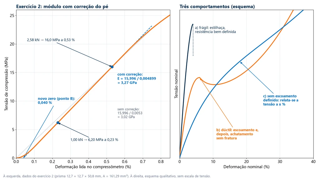
- Stresses: σ1 = 1,000 / 161.29 = 6.200 MPa; σ2 = 2,580 / 161.29 = 15.996 MPa.
- Slope of the line: (15.996 − 6.200) / (0.0053 − 0.0023) = 9.796 / 0.0030 = 3,265 MPa.
- New zero: the line crosses zero stress at ε = 0.0023 − 6.200 / 3,265 = 0.0023 − 0.001899 = 0.000401, or 0.040%.
- Modulus per the standard: at point 2, the strain measured from the new zero is 0.0053 − 0.000401 = 0.004899, and E = 15.996 / 0.004899 = 3,265 MPa, reported as 3.27 GPa.
- Without the correction: 15.996 / 0.0053 = 3,018 MPa, or 3.02 GPa, which is 7.6% lower.
As expected, the corrected modulus equals the slope of the line. The error without the correction comes from dividing the stress by a strain that still includes the toe. The value is close to the 3.28 GPa from the interlaboratory study for acetal. On a 25 mm compressometer, point 2 is a shortening of 0.0053 × 25 = 0.1325 mm, which shows how much resolution the instrument needs.
Example 3: is the specimen suitable for modulus?
A laboratory wants to measure modulus on 12.7 mm diameter cylinders and already has machined 12.7 × 12.7 × 38.1 mm prisms. What cylinder height should it use, and are the prisms suitable?
- Cylinder: Rg = 0.25 × 12.7 = 3.175 mm. For a slenderness ratio λ between 11 and 16, L ranges from 11 × 3.175 = 34.9 mm to 16 × 3.175 = 50.8 mm. The preferred height, 50.8 mm, is at the upper limit.
- 38.1 mm prism: Rg = 0.289 × 12.7 = 3.67 mm and λ = 38.1 / 3.67 = 10.4, which is below 11. It is not suitable for modulus.
- Prism range: L from 11 × 3.67 = 40.4 mm to 16 × 3.67 = 58.7 mm. The preferred height, 50.8 mm, gives λ = 13.8.
Can the 38.1 mm prisms still be used for strength? No. For strength, the length is twice the width, 25.4 mm, so they would have to be cut down.
Example 4: what machine capacity is needed
A laboratory will test the standard prism in acetal (about 100 MPa), polystyrene (about 106 MPa) and filled phenolic (about 158 MPa). It wants to know whether the 10 kN single-column machine is enough. The expected maximum force is F = σ × A, with A = 161.29 mm². The chart below compares these forces, plus those for POM-C and PA6 at 5% strain, with the forces on the ISO 604 type B specimen (40 mm²). It also marks the 10 kN and 30 kN limits.
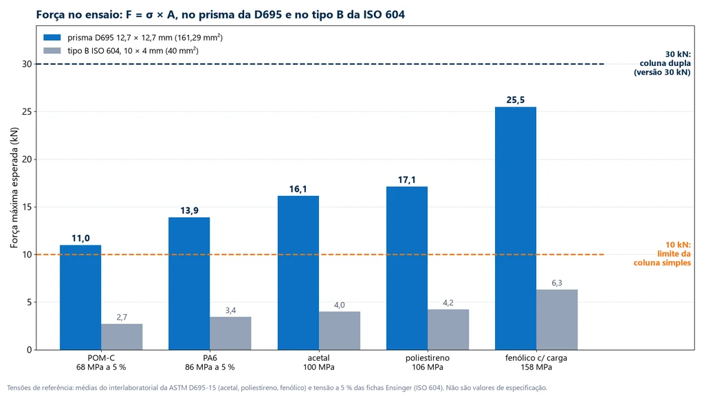
- Acetal: 100 × 161.29 = 16,129 N, about 16.1 kN.
- Polystyrene: 106 × 161.29 = 17,097 N, about 17.1 kN.
- Filled phenolic: 158 × 161.29 = 25,484 N, about 25.5 kN.
- Conclusion: all of them exceed 10 kN, so the single-column machine cannot test the standard prism of these materials. A 30 kN dual-column machine would run at 85% of capacity on the phenolic. A 50 kN version would run at 51%, with headroom for stronger materials.
- Under ISO 604: type B needs only 158 × 40 = 6,320 N, or 6.3 kN, which the single-column machine can handle. In that case, though, the test is ISO 604, not D695.
Even a thermoplastic that does not fracture exceeds 10 kN on the standard prism if the test runs to 5% strain: 86 MPa in PA6 gives 13.9 kN.
Common mistakes when applying ASTM D695
The mistakes below show up in test reports, purchase specifications and pages that explain the standard. Each one has a simple fix:
- Citing D695-15 or D695-02 as the current edition. The current edition is D695-26.
- Testing the modulus specimen for strength, or the other way around. The strength specimen is twice as tall as it is wide. The modulus specimen has a slenderness ratio of 11 to 16.
- Testing thin material without a support jig. Below 3.2 mm, the specimen buckles. The signs are a curve that drops early and a bowed specimen.
- Sawn or non-parallel ends. The tolerance is 0.025 mm. Ends outside this tolerance lengthen the toe of the curve and lower the measured strength.
- Using the nominal area. The standard requires the smallest measured cross-section.
- Calculating modulus from crosshead displacement. This gives a low modulus. The standard requires a compressometer on the specimen.
- Skipping the toe correction. In example 2, the modulus would drop by 7.6%, and every strain value would be shifted.
- Reporting "strength" for a material that flattened without fracturing. In that case, report the yield strength or the stress at a defined strain, and state the criterion.
- Conditioning the prism for 40 h. At 12.7 mm thick, D618 procedure A requires 88 h.
- Ignoring friction at the ends. Friction between the platens and the specimen keeps the end faces from expanding sideways, so a ductile specimen barrels. This confinement raises the nominal stress. It is one more reason not to call the force at the end of a test without fracture a strength value. D695 does not specify lubrication of the ends.
- Using D695 for unidirectional carbon composites. Continuous oriented fiber composites are tested to D3410/D3410M or D6641/D6641M.
- Describing compressive modulus as flexural or stretching strength. Compressive modulus is the slope of the linear portion of the compressive stress-strain curve. Flexure is covered by D790, and tension by D638.
- Mixing D695 and ISO 604 results in the same table, or confusing D695 with D642, which covers packaging.
Equipment for ASTM D695 testing
The test requires a universal testing machine with constant crosshead speed, flat and parallel compression platens, a load cell accurate to within ±1%, and a compressometer on the specimen for modulus. In Biopdi's M2 line, the MBIOII-50-M2 dual-column machine comes in versions from 5 to 50 kN. Its speed range is 0.02 to 500 mm/min, which covers the 1.3 mm/min of the test and the 5 to 6 mm/min used after yield. The load cell is class 1 per ISO 7500-1 (ABNT NBR ISO 7500-1:2023 in Brazil), and the BioLab software records the curve and generates the report. The panel below shows the machine, what each part does in a D695 test, and the fixtures used.
The universal testing machine in compression testing of plastics
For the standard D695 prism, the starting point is the dual-column machine, because the force exceeds 10 kN. The single-column machine, from 200 N to 10 kN, handles small specimens and low-strength materials. Each part of the machine has a role in the test:

- Moving crosshead brings the platens together at 1.3 mm/min
- Load cell measures the maximum force, class 1
- Compression platens are flat and parallel, with the prism between them
- Compressometer measures strain on the specimen
- BioLab software gives the curve, strength, average and standard deviation
- Control panel and emergency stop position the crosshead and stop the test
Fixtures for compression testing of plastics
The platens and extensometers below mount on the same machine and are chosen by specimen type and the result required:
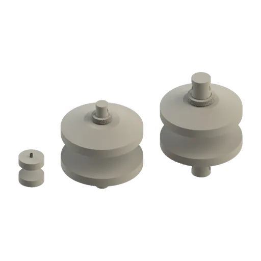
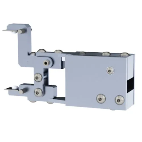
Choose the model based on the expected maximum force, as in example 4. The table shows the recommended model for each application:
| Application | Typical force | Biopdi model |
|---|---|---|
| ISO 604 type B, foams, low-strength plastics | up to about 7 kN | MBIOI-10-M2 (2, 5 or 10 kN) with 1 or 50 kN platens |
| D695 prism, engineering thermoplastics | 11 to 18 kN | MBIOII-50-M2 (30 or 50 kN) with 50 kN platens |
| D695 prism, thermosets and filled plastics | 20 to 30 kN | MBIOII-50-M2 (50 kN) with 50 kN platens |
The 25 mm gauge length extensometer fits on the 50.8 mm prism and measures strain for the modulus. The M2 line's fixture list does not include a subpress or an anti-buckling support jig for thin specimens. For fixtures like these, contact us about special projects. The same machine also runs tensile tests on plastics to ASTM D638 and flexural tests to ASTM D790. Our article on the universal testing machine explains how it works. For a proposal configured for your laboratory, request a quote.
Standards cited
The table lists the standards cited in this guide. Editions and status were checked on September 30, 2026 in the ASTM store (store.astm.org) and the ISO catalog, and the current D695 edition was checked again on October 1, 2026:
| Standard | Subject | Edition and status |
|---|---|---|
| ASTM D695 | compression testing of rigid plastics | D695-26, active |
| ISO 604 | compression testing of plastics | 2002 (3rd edition), confirmed in 2022 |
| ASTM D618 | conditioning of plastics | D618-21, active |
| ASTM E4 | force verification of testing machines | E4-24, active |
| ASTM E83 | verification and classification of extensometers | E83-25, active |
| ASTM D3410/D3410M | compression testing of composites by shear loading through the grips | D3410/D3410M-16, reapproved in 2024 |
| ASTM D6641/D6641M | compression testing of composites with combined loading | D6641/D6641M-23, active |
| ASTM D642 | compression testing of shipping containers and unit loads | D642-25, active |
| ISO 14126 | in-plane compression testing of fiber-reinforced composites | 2023, replaces the 1999 edition |
| ABNT NBR ISO 7500-1 | verification of the testing machine's force-measuring system (Brazilian adoption of ISO 7500-1) | 2023 |
Other tests and technical references
Tests performed on the Biopdi universal testing machine



















Related technical references
ASTM D790: three-point flexural test of plastics (procedures A and B, support span and calculations)
ASTM D790-25 measures the flexural strength and flexural modulus of plastics using a bar on two supports loaded at midspan. The support span is 16 times the thickness. The strain rate is 1%/min (procedure A) or 10%/min (procedure B), and the test runs until the specimen breaks or reaches 5% strain. Covers the crosshead speed R = ZL²/6d, the formulas, the large-deflection correction, a comparison with ISO 178 and D6272, and worked examples.
Tensile test: what it is, step by step, calculations and standards (ISO 6892-1)
A tensile test pulls a specimen axially to fracture to measure yield strength, UTS, modulus and elongation. Calculations, steps, standards and specimens.
ASTM D638: tensile testing of plastics, Type I to V specimens, test speed and calculations
ASTM D638-22 is the ASTM method for the tensile properties of plastics up to 14 mm thick, using Type I to V dumbbell specimens. See dimensions, test speed, conditioning, extensometer, formulas, a worked example and the differences from ISO 527-2:2025.
Frequently asked questions
What is ASTM D695?
It is the ASTM test method for the compressive properties of rigid plastics, reinforced or unreinforced, including high-modulus composites up to 41,370 MPa. It measures compressive strength, yield, modulus of elasticity and strain. The current edition is D695-26.
What is the current edition of ASTM D695?
The current edition is ASTM D695-26, active in the ASTM store as of October 1, 2026, and it replaces D695-23. Pages that cite D695-15 or D695-02 as current are out of date; the standard has existed since 1942.
What is a compression test?
It is a test that applies an increasing axial force to a test specimen, shortening it, and records force and strain to obtain compressive strength, yield and modulus. The general principle, for metals, concrete and plastics, is covered in the article compression test.
What is the typical specimen size for ASTM D695?
For strength, a 12.7 × 12.7 × 25.4 mm prism or a cylinder 12.7 mm in diameter by 25.4 mm long, with a height twice the width. For modulus and offset yield, 12.7 × 12.7 × 50.8 mm or a 12.7 × 50.8 mm cylinder, with a slenderness ratio between 11 and 16.
What is the test speed in ASTM D695?
1.3 ± 0.3 mm/min, measured between the loading surfaces. For relatively ductile materials, after yield, the speed may be increased to 5 to 6 mm/min until failure, provided the force system responds quickly.
How is compressive strength calculated under D695?
The maximum force during the test is divided by the minimum original cross-sectional area, and the result is reported in MPa to three significant figures. A 161.29 mm² prism with a maximum force of 16.2 kN has a compressive strength of 100 MPa.
Why do many plastics not fracture in a compression test?
Because in compression the cross section increases and cracks are closed by the load. Ductile plastics deform until they become a flattened disc, with stress still rising and no definite fracture. In that case the strength is arbitrary, and the yield or the stress at a defined strain is reported instead.
When is the anti-buckling support jig used?
For materials less than 3.2 mm thick, or when the modulus specimen is not long enough for the compressometer. The specimen specified for this case is placed in a support jig of plates tightened by hand only, which prevents buckling without carrying the load.
Does ASTM D695 require a compressometer?
For modulus and the stress-strain curve, yes: strain is measured on the specimen with a class B-2 instrument per ASTM E83. To measure strength only, the maximum force is enough.
How many specimens does D695 require?
At least five per sample for isotropic materials and ten for anisotropic materials, five in each direction. A specimen that fails at an obvious flaw is discarded and replaced.
Do ASTM D695 and ISO 604 give the same results?
Not necessarily. D695 uses a 12.7 mm prism, 1.3 mm/min and a tangent modulus with toe compensation; ISO 604:2002 uses specimens with a 10 × 4 mm cross section, speeds from 1 to 20 mm/min and a chord modulus between 0.05% and 0.25%. The results are not interchangeable.
Can carbon fiber composites be tested to D695?
Only if the composite modulus is no higher than 41,370 MPa and the reinforcement is not continuous and oriented. Unidirectional and cross-ply laminates go to ASTM D3410/D3410M, D6641/D6641M or ISO 14126:2023, or to the aerospace variants of modified D695, such as Boeing BSS 7260.
What is ASTM D642?
It is the standard for the compressive resistance of shipping containers, components and unit loads, such as boxes and drums, with the load applied on the faces, edges or corners. The current edition is D642-25. It tests the package, not the plastic material.
What is ASTM D638 used for?
It is the tensile test method for plastics, using dumbbell-shaped (dog-bone) specimens, and it measures tensile strength, elongation and modulus. It is the tensile counterpart of D695, and the current edition is D638-22.
What machine is needed for ASTM D695?
A constant-speed universal testing machine with force accuracy of ±1% verified annually, flat and parallel compression platens, and a compressometer for modulus. On the standard prism, a 100 MPa engineering plastic requires about 16 kN, more than a 10 kN single-column machine can deliver.