
Strength of materials is the engineering discipline that calculates the stresses and strains that loads cause in deformable parts, so that they do not fracture, do not yield and do not deform too much. Statics treats the body as rigid; strength of materials accepts that it deforms and uses properties measured in tests. The core calculation is always the same: find the internal force, convert it into stress (σ = N / A in simple tension) and compare it with the allowable stress of the material.
The reasoning of the discipline fits into four steps:
- Internal forces: the equilibrium of the part gives, at each section, the normal force N, the shear force V, the bending moment M and the torque T.
- Stresses: each internal force becomes a normal stress σ or a shear stress τ, through a formula that depends on the geometry of the section.
- Check: the service stress is compared with the allowable stress, σadm = σe / n, and the displacement with the design limit.
- Material data: the modulus of elasticity E, the yield strength σe and the ultimate tensile strength σr come from testing, usually the tensile test.
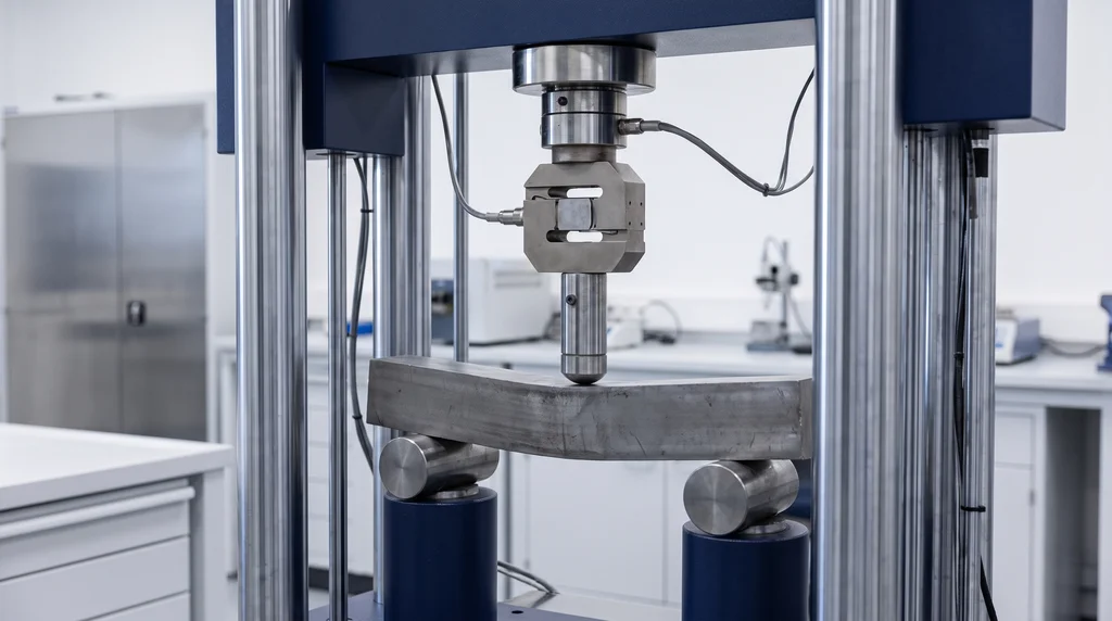
This guide explains the concepts in that order, gathers a table of formulas with units and range of validity, solves five numerical exercises and recommends the course textbooks. In the photo, a steel bar under three-point bending in the universal testing machine: two rollers support the ends, the loading nose loads the middle of the span and the bar bends without breaking, the same problem that beam theory describes on paper.
What is strength of materials
Strength of materials is the branch of applied mechanics that relates the external loads acting on a deformable body to the internal forces, stresses and strains they produce. The Strength of Materials I lecture notes from UFJF (Federal University of Juiz de Fora, 2012), one of the most widely used open course materials in Brazil, define the discipline as a "science developed from experimental tests and theoretical analyses": the formulas come from theory, and the numbers that go into them come from the laboratory.
Statics and strength of materials
The difference between the two disciplines lies in the assumption about the body. Statics assumes the body is perfectly rigid and answers one question: which forces and reactions keep the part in equilibrium. Strength of materials starts from those forces and answers two others: how much each point of the part is loaded (the stress) and how much the part changes shape (the strain and the displacement). A steel beam and a wood beam with the same span and the same load have the same support reactions in statics; in strength of materials they have different deflections, because the modulus of elasticity of each material is different.
Discipline and property: strength of materials × mechanical strength
"Strength of materials" is the name of the discipline; "mechanical strength" is a property of the material, the maximum stress it withstands before yielding or fracturing. The confusion is common, and the Portuguese-language Wikipedia itself opens its entry on the discipline by defining the property. The property, with yield, ultimate strength and how each is measured, is covered in the article on mechanical strength; the complete list of properties, with the unit, test and standard for each, is in mechanical properties of materials. Here the subject is the discipline, which uses these properties as input data.
Mechanics of materials is the same as strength of materials
"Mechanics of materials" is another name for the same discipline. It is the title used in the books by Beer and Johnston and by Gere and Goodno, Mechanics of Materials, while "strength of materials" (resistência dos materiais) is the traditional name in Portuguese and the Brazilian title of Hibbeler's book. In Portugal, "resistência de materiais" is also used. In graduate course syllabi, the continuation of the discipline is usually called solid mechanics or theory of elasticity.
The assumptions of the course
The formulas of the basic course are valid within a set of simplifying assumptions, and many application errors come from forgetting them:
- Homogeneous and isotropic material: the properties are the same at every point and in every direction, which holds well for steel and poorly for wood and composites;
- Linear elastic behavior: stress is proportional to strain (Hooke's law) and the part returns to its original shape when the load is removed;
- Small deformations: the geometry changes so little that equilibrium can be written in the undeformed shape;
- Saint-Venant's principle: away from the load application point, holes and changes of section, the stress distribution depends only on the resultant internal force, not on the exact way the load was applied.
Brief history
Galileo Galilei treated the strength of beams in Discorsi e dimostrazioni matematiche intorno a due nuove scienze (Leiden, 1638), and one of the two "new sciences" in the title is precisely strength of materials, studied with the cantilever beam. Robert Hooke published the proportionality between force and elongation in 1678 ("ut tensio, sic vis"), and Leonhard Euler derived the critical buckling load of columns in 1744, in an appendix to Methodus inveniendi lineas curvas. The complete history of the discipline, up to the 20th century, is in History of Strength of Materials, by Stephen Timoshenko (McGraw-Hill, 1953).
What it is used for and where it fits in the engineering curriculum
Strength of materials is used to size and check parts: choosing the section of a beam, the diameter of a shaft, the number of bolts in a connection or the thickness of a plate so that the part carries the load safely and without deforming beyond what is acceptable. It is the discipline that turns the equilibrium of statics into a design decision.
Applications by engineering field
Every engineering field that designs physical objects uses the discipline, each with its own focus:
- Civil engineering: beams, columns, slabs, trusses and connections; it is the basis for the Brazilian design standards for steel structures (ABNT NBR 8800) and concrete structures (ABNT NBR 6118);
- Mechanical engineering: transmission shafts, springs, bolts, pressure vessels and machine elements;
- Materials engineering: the link between the microstructure and the properties that go into the formulas, and the test that measures them;
- Industrial engineering: choice of material and process, fixtures and quality control of components.
Prerequisites and follow-on courses
Strength of materials usually comes after Statics (or General Mechanics) and Calculus, in the basic cycle of engineering programs, and many schools split it into Strength of Materials I and II. The split and the semester vary by institution. The UFJF lecture notes give a typical picture of the first course in Brazil: stresses and strains, tension and compression, shear, torsion, bending, shear in beams, deflection of beams and statically indeterminate problems. Then come Structural Analysis, Concrete and Steel Structures, Machine Elements and, at graduate level, Solid Mechanics.
Is strength of materials difficult?
It is one of the most demanding courses of the basic cycle, because it brings together three things the student has seen separately: the equilibrium of statics, integral calculus and the geometry of sections (centroid and moment of inertia). The engineering education literature records a specific point of difficulty: the study by Creuziger and Crone, from the University of Wisconsin-Madison, presented at the ASEE annual conference in 2006, starts from the finding that shear stress is a difficult concept for students when it first appears in the course. In practice, three habits solve much of the problem: always work in N, mm and MPa, draw the free-body diagram before any formula and check whether the result makes physical sense, as the exercises in this article do.
Internal forces: normal force, shear force, bending moment and torque
Internal forces are the forces and moments that one part of the component transmits to the other through a section. To find them, the method of sections is used: the part is cut by an imaginary plane at the point of interest, one side is isolated and equilibrium is applied to it. The forces that appear on the cut face are exactly those that keep the isolated segment in equilibrium. In a general problem there are six components, which group into four internal forces:
| Internal force | Symbol | Stress it causes | Example |
|---|---|---|---|
| Normal force | N | Uniform σ (tension positive, compression negative) | Tie rod, cable, column |
| Shear force | V | τ on the section | Bolt in a joint, beam web |
| Bending moment | M | Linear σ: tension on one side, compression on the other | Beam, shelf, supported shaft |
| Torque (twisting moment) | T | τ linear with the radius | Transmission shaft, open-end wrench |
The diagram below shows, for each internal force, the segment isolated by the cut with the force on the face and, below it, how the stress is distributed over the section. Note that only the normal force produces uniform stress; in the other three cases the stress varies from point to point, and it is the maximum value, at the most heavily loaded fiber, that matters for design.
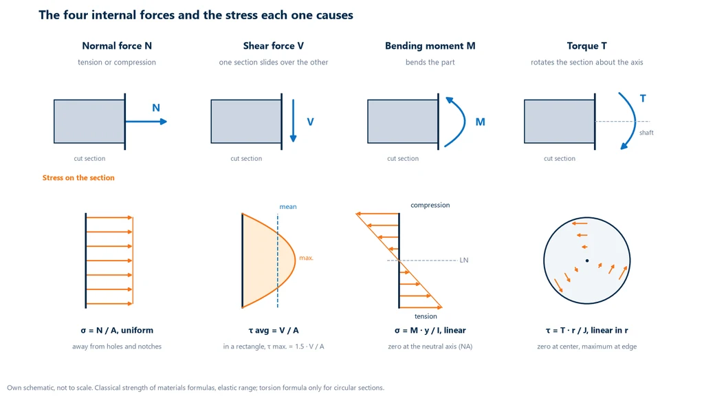
Internal force diagrams
Since the internal forces change along the part, the course teaches how to plot them: the normal force diagram, the shear force diagram and the bending moment diagram. The point of highest value on the diagram indicates the critical section, where the check is made. In a simply supported beam with a load at mid-span, for example, the moment is zero at the supports and maximum under the load, P · L / 4; that is where the beam works hardest, as exercise 3 shows. Two relationships help check the diagrams: the slope of the moment diagram equals the shear force, and the moment is maximum where the shear force changes sign.
Stress and strain
Stress is the internal force per unit area of a section, and strain is the relative change of shape that this force produces. These two quantities make the calculation independent of the size of the part: a thin bar and a thick bar of the same steel yield at the same stress, although at very different forces.
Normal stress and shear stress
Normal stress, σ, acts perpendicular to the section: σ = N / A, where N is the normal force and A the area. Shear stress, τ, acts in the plane of the section and, in its simplest form, is the average τ = V / A. The SI unit is the pascal (Pa = N/m²), too small for engineering; in practice the megapascal is used, and one shortcut avoids most errors: 1 MPa = 1 N/mm². With force in newtons and area in square millimeters, the division comes out directly in MPa.
Normal strain and shear strain
Normal strain, ε, is the elongation divided by the initial length, ε = δ / L0, dimensionless; it is commonly expressed in %, in mm/mm or in microstrain (µε, 10−6). Shear strain, γ, is the change in the right angle between two lines of the part, measured in radians. When a bar is pulled in tension, it lengthens in the load direction and becomes thinner in the transverse direction; the ratio between the two strains is Poisson's ratio, ν = − εlat / εlong.
Hooke's law and elastic constants
In the elastic range, stress is proportional to strain: σ = E · ε, Hooke's law written in terms of stress, which does not depend on the geometry of the part. The constant E is the modulus of elasticity, or Young's modulus, and measures the stiffness of the material. In shear, the same law becomes τ = G · γ, where G is the shear modulus. In an isotropic material, the three constants are related by G = E / [2 (1 + ν)]. For structural steel, ABNT NBR 8800 (the Brazilian standard for the design of steel structures) adopts E = 200 GPa; with ν = 0.3, the relationship gives G = 200 / 2.6 = 76.9 GPa, the roughly 77 GPa used in textbooks (Biopdi calculation). The law holds only up to the proportional limit; beyond it, the curve departs from the straight line and the elastic formulas no longer apply.
Where E, σe and σr come from: the tensile test
The three numbers that feed almost every calculation come from the tensile test: a standardized test specimen is pulled to fracture in a universal testing machine, the load cell measures the force, the extensometer measures the elongation and the software converts everything into stress and strain. The graph below shows a schematic stress-strain curve of a ductile steel with only the three marks that matter here, and where each one goes: the slope of the initial segment is the modulus E; the yield strength σe is read where a line parallel to the elastic segment, offset by 0.2% strain, intersects the curve; and the ultimate tensile strength σr is the highest point.
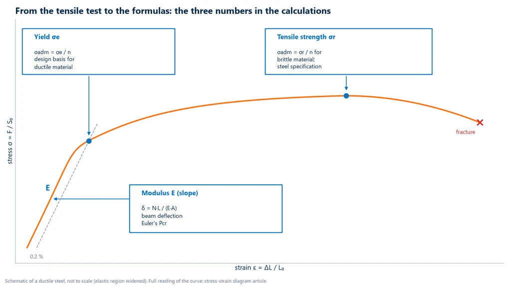
Without these numbers, the formulas have nothing to calculate. The complete reading of the curve, with the proportional limit, the yield plateau, necking and the true stress-strain curve, is in the article on the stress-strain curve. For metals, the test follows ISO 6892-1:2024 (ABNT NBR ISO 6892-1 in Brazil) or ASTM E8/E8M-25, and accurate determination of the modulus has its own standard, ASTM E111-17(2025)e1 (editions checked on 10/07/2026).
Strength of materials formula table
The formulas of strength of materials relate each internal force to the stress or displacement it produces. The table brings together the main formulas of the introductory course, with practical units (N, mm, MPa) and the range of validity of each one. These are the classic forms found in the textbooks by Hibbeler, by Beer and Johnston, and by Gere and Goodno, and all of them assume a homogeneous, isotropic material in the linear elastic range:
| Quantity | Formula | Practical units | When it applies |
|---|---|---|---|
| Average normal stress | σ = N / A | N, mm² → MPa | Centric axial load, away from holes and notches |
| Average shear stress | τ = V / A | N, mm² → MPa | Average value; in a beam the maximum is higher (1.5 × for a rectangle) |
| Normal strain | ε = δ / L0 | dimensionless (mm/mm, %, µε) | Small strains |
| Hooke's law | σ = E · ε ; τ = G · γ | E and G in MPa (200 GPa = 200,000 MPa) | Up to the proportional limit |
| Relationship between constants | G = E / [2 (1 + ν)] | MPa | Isotropic material |
| Elongation of a bar | δ = N · L / (E · A) | mm | N, E and A constant over the segment |
| Bending (Navier) | σ = M · y / I ; σmáx = M / W | M in N·mm, I in mm⁴ → MPa | Plane sections remain plane; linear material |
| Moment of inertia | rectangle: b · h³ / 12 ; circle: π · d⁴ / 64 | mm⁴ | About the centroidal bending axis |
| Section modulus | W = I / c ; rectangle: b · h² / 6 | mm³ | c = distance from the neutral axis to the extreme fiber |
| Maximum shear in a rectangular beam | τmáx = 1.5 · V / A | MPa | Rectangular section, at the neutral axis |
| Torsion | τ = T · r / J ; τmáx = 16 T / (π d³) | T in N·mm → MPa | Circular sections only, solid or hollow |
| Polar moment of inertia | solid: π d⁴ / 32 ; tube: π (D⁴ − d⁴) / 32 | mm⁴ | Circular section |
| Angle of twist | φ = T · L / (G · J) | rad | T, G and J constant over the segment |
| Euler buckling | Pcr = π² · E · I / (K · L)² | N (with minimum I) | Slender column: σcr below the proportional limit |
| Critical stress | σcr = π² · E / (K L / r)² ; r = √(I / A) | MPa | Same as above |
| Allowable stress | σadm = σe / n (or σr / n) | MPa | Allowable stress design; n > 1 |
The "when it applies" column is as important as the formula. A formula sheet without the limits leads to the most common mistakes of the course, such as using τ = T · r / J on a square bar or applying Euler to a short column. The following sections explain each group of formulas and its limit.
Axial load: tension and compression
An axial load is a force applied along the axis of the member, which stretches it (tension) or shortens it (compression) without bending it. The stress is σ = N / A, uniform over the section as long as the load passes through the centroid and the section is away from holes and abrupt changes in diameter. The elongation comes from Hooke's law: since σ = E · ε and ε = δ / L, we get δ = N · L / (E · A). The formula shows that elongation increases with force and length and decreases with the stiffness of the material and with the area.
The usual sign convention is tension positive and compression negative. In compression, the same formulas apply as long as the member is short; if it is slender, another failure mode appears first, buckling, covered further below. When the member has segments with different areas or forces, the total elongation is the sum of the elongations of each segment. The test that measures a material's response to axial compressive load is covered in the article on the compression test.
Bending of beams
Bending is the behavior of a member loaded transversely to its axis, such as a beam or a shelf: it curves, the fibers on one side stretch and those on the other side shorten. Between the two there is a surface that does not change length, the neutral axis, which passes through the centroid of the section when the material is linear and there is no normal force.
The Navier formula
The normal stress in bending varies linearly with the distance from the neutral axis: σ = M · y / I, where M is the bending moment at the section, y is the distance from the point to the neutral axis and I is the moment of inertia of the section about the bending axis. The stress is zero at the neutral axis and maximum at the outermost fibers, at a distance c; that is why design uses σmáx = M · c / I = M / W, where W = I / c is the section modulus. In a simply supported beam with a downward load, the top fibers are in compression and the bottom fibers in tension.
Why a beam works "on edge"
The moment of inertia of a rectangle is b · h³ / 12: it grows with the cube of the height and only linearly with the width. Rotating the same member so that its larger dimension is vertical greatly increases I and, with it, reduces stress and deflection. This is the same reason I-beams and box girders concentrate material far from the neutral axis, where it contributes most to I. Exercise 3 shows the effect in numbers: the same 100 × 200 mm member works at twice the stress when laid flat.
Shear in bending
In addition to the moment, the beam carries a shear force, which produces shear stress in the section. This stress is not uniform: it is zero at the extreme fibers and maximum at the neutral axis, and in a rectangular section the maximum is 1.5 times the average, τmáx = 1.5 · V / A, from the general expression τ = V · Q / (I · t) found in textbooks. In long, slender beams, the normal bending stress usually governs the design; in short beams, heavily loaded near the support, or in timber beams, shear can be decisive. The test that reproduces bending in the laboratory, with three-point or four-point loading, is covered in the article on the flexural test.
Torsion of circular shafts
Torsion is loading by a moment about the axis of the member, the typical case of a drive shaft or a wrench tightening a bolt. In a circular section, each section rotates relative to the next like a rigid disk, and the shear stress increases linearly from the center, where it is zero, to the surface: τ = T · r / J, where T is the torque, r is the distance from the center and J is the polar moment of inertia (π · d⁴ / 32 for a solid shaft). At the surface, τmáx = 16 T / (π d³).
The angle of twist between two sections a distance L apart is φ = T · L / (G · J), in radians. It is to torsion what δ = N L / (E A) is to axial load, with G in place of E and J in place of A. The formula is used to check the stiffness of the shaft: a shaft can withstand the stress and still twist too much for the mechanism to work.
Since the stress at the center is small, the material there contributes little: a hollow shaft transmits almost the same torque with much less mass, which is why many vehicle driveshafts are tubes. The formulas do not apply to non-circular sections, however: a square bar or an open section warps when twisted, the sections no longer remain plane, and the maximum stress occurs at the middle of the side, not at the corner. The test that measures torque, angle of twist and shear modulus G is covered in the article on the torsion test.
Buckling of columns
Buckling is the loss of stability of a slender member in compression: above a critical load, the column stops shortening in a straight line and suddenly bends sideways, even with the stress well below yield. It is a failure mode governed by geometry, not by the strength of the material.
The Euler critical load
For an ideal column, straight, centrically loaded and made of an elastic material, the critical load is Pcr = π² · E · I / (K · L)². The product K · L is the effective length, Le, and I is the minimum moment of inertia of the section, because the column buckles toward the side where it is least stiff. The formula has two consequences that surprise those who see it for the first time:
- The critical load does not depend on the strength of the material. It depends on E, and the modulus of elasticity is practically the same for all steels, about 200 GPa. A slender column of high-strength steel buckles at the same load as one of ordinary steel with the same geometry.
- The load decreases with the square of the length. Doubling the length divides the critical load by four.
End conditions and the K factor
The effective length factor K reflects the end conditions: the more restrained the ends, the shorter the "half-wave" of the buckled shape and the higher the critical load. The theoretical values are 1.0 for a pinned-pinned column, 2.0 for a fixed-free column, 0.7 for a fixed-pinned column and 0.5 for a fixed-fixed column. The diagram below draws the buckled shape of each case and calculates the critical load for the same solid steel bar, 30 mm in diameter and 2 m long, the bar of exercise 5: the load ranges from 4.9 kN, with one free end, to 78.5 kN, with both ends fixed, a 16-fold difference due only to how the bar is restrained.
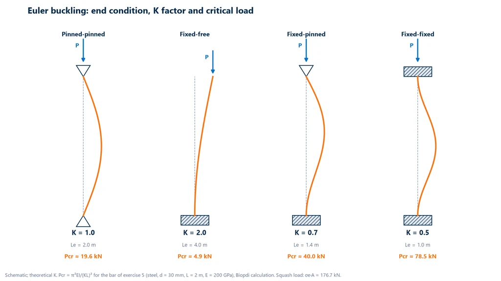
Design codes recommend K values slightly higher than the theoretical ones for cases with fixed ends, because a real fixed support is never perfectly rigid. When checking a structure, use the value from the applicable code.
When the Euler formula applies
Euler assumes the material remains elastic throughout buckling, so the formula only applies if the critical stress σcr = Pcr / A stays below the proportional limit. The practical way to check this is through the slenderness ratio, K · L / r, where r = √(I / A) is the radius of gyration. Taking σe = 250 MPa and E = 200 GPa as a reference, σcr = σe when K L / r = π · √(E / σe) ≈ 89 (Biopdi calculation). Columns more slender than this follow Euler; short and intermediate columns fail by a combination of yielding and instability, and for them inelastic formulas or the strength curves of design codes are used.
Allowable stress and factor of safety
Allowable stress is the highest stress the design permits in a member in service: the material limit divided by a factor of safety greater than 1, σadm = σlim / n. The factor of safety, n, is the ratio between the stress (or load) that causes failure and the service stress (or load). It exists to cover what the calculation does not know exactly: the actual load, which may exceed the expected one; the scatter of the material, because not every batch has the strength measured in the test; the simplifications of the model; and manufacturing and assembly defects.
Which limit to use
The choice of limit depends on the behavior of the material:
- Ductile material (structural steel, aluminum, copper): the yield strength is used, σadm = σe / n, because a member that yields has already deformed permanently and is no longer serviceable, even without fracturing.
- Brittle material (gray cast iron, ceramics, glass, concrete in tension): there is no defined yield point, and the ultimate strength is used, σadm = σr / n, usually with a higher n, because fracture occurs without warning.
A factor of safety without an indication of the limit means nothing. In exercise 1, the same bar has n = 1.57 with respect to yield and n = 2.51 with respect to fracture, with the same steel and the same load.
Allowable stress vs. code limit states
The single "n" is the teaching form of allowable stress design, the method of introductory course textbooks. Brazilian structural standards work differently: ABNT NBR 8800:2024 (the Brazilian standard for the design of steel and composite steel-concrete structures for buildings; corrected version of 2025, edition checked on 10/07/2026 in the catalog entry) and ABNT NBR 6118 (the Brazilian standard for the design of concrete structures) use the limit state method, in which loads are increased and resistances reduced by partial factors, separated by type of action and of material. Students should master allowable stress to understand the reasoning, but the design of a real structure follows the factors and load combinations of the applicable code.
Strength of materials: solved problems
The five problems below cover the core topics of the course, one for each type of loading, and all of them were calculated and checked by Biopdi. The properties are those of structural steel used throughout the articles on this site: E = 200 GPa, G = 77 GPa and σe = 250 MPa, the minimum yield strength of ASTM A36 steel, whose specified ultimate tensile strength ranges from 400 to 550 MPa. All of them use N, mm and MPa.
Problem 1: tension, design check and elongation
A solid A36 steel bar, 20 mm in diameter and 2.0 m long, is loaded in tension with 50 kN. With a factor of safety n = 1.5 against yielding, is the bar adequate? How much does it elongate?
- Area: A = π · d² / 4 = π · 20² / 4 = 314.16 mm².
- Stress: σ = N / A = 50,000 / 314.16 = 159.2 MPa.
- Allowable stress: σadm = 250 / 1.5 = 166.7 MPa. Since 159.2 < 166.7, the bar is adequate.
- Elongation: δ = N · L / (E · A) = 50,000 × 2,000 / (200,000 × 314.16) = 1.59 mm.
- Check through strain: ε = σ / E = 159.2 / 200,000 = 7.96 · 10−4, or 0.080%; δ = ε · L = 0.000796 × 2,000 = 1.59 mm.
Answer: σ ≈ 159 MPa, below the allowable 167 MPa; elongation of 1.6 mm. The actual factor of safety is 250 / 159.2 = 1.57 against yielding and 400 / 159.2 = 2.51 against the minimum ultimate tensile strength of A36.
Problem 2: shear in a bolt
Two overlapping plates are joined by a single 12 mm diameter bolt in single shear (only one cross section of the bolt is sheared), and the joint transmits 10 kN. What is the average shear stress in the bolt?
- Shear area: A = π · 12² / 4 = 113.1 mm².
- Average stress: τ = V / A = 10,000 / 113.1 = 88.4 MPa.
Answer: τ ≈ 88 MPa. This is an average stress, and the actual check of a bolted connection follows the design code, which also considers bearing of the plate at the hole and rupture of the plate at the net section through the hole. If the same joint had two shear planes (double shear, with the bolt passing through three plates), the stress would drop by half, to 44.2 MPa.
Problem 3: bending of a simply supported beam
A beam with a rectangular cross section, b = 100 mm and h = 200 mm, spans 4 m between two supports and carries a concentrated load of 10 kN at midspan. Neglecting self-weight, what is the maximum normal stress? And what if the same member were installed lying flat?
- Maximum moment, under the load: M = P · L / 4 = 10 × 4 / 4 = 10 kN·m = 10 · 106 N·mm.
- Moment of inertia, upright: I = b · h³ / 12 = 100 × 200³ / 12 = 6.667 · 107 mm⁴, with c = h / 2 = 100 mm.
- Maximum stress: σ = M · c / I = 10 · 106 × 100 / 6.667 · 107 = 15.0 MPa. Check: W = b · h² / 6 = 666,667 mm³ and σ = M / W = 15.0 MPa.
- Lying flat (b = 200 mm, h = 100 mm): I = 200 × 100³ / 12 = 1.667 · 107 mm⁴, c = 50 mm and σ = 10 · 106 × 50 / 1.667 · 107 = 30.0 MPa.
- Shear: the shear force is V = P / 2 = 5 kN, and the maximum stress, at the neutral axis, is τ = 1.5 × 5,000 / (100 × 200) = 0.375 MPa.
The diagram below brings the steps together: the beam with the load, the bending moment diagram with its maximum under the load, and the linear stress distribution for both orientations of the cross section, drawn to the same scale.
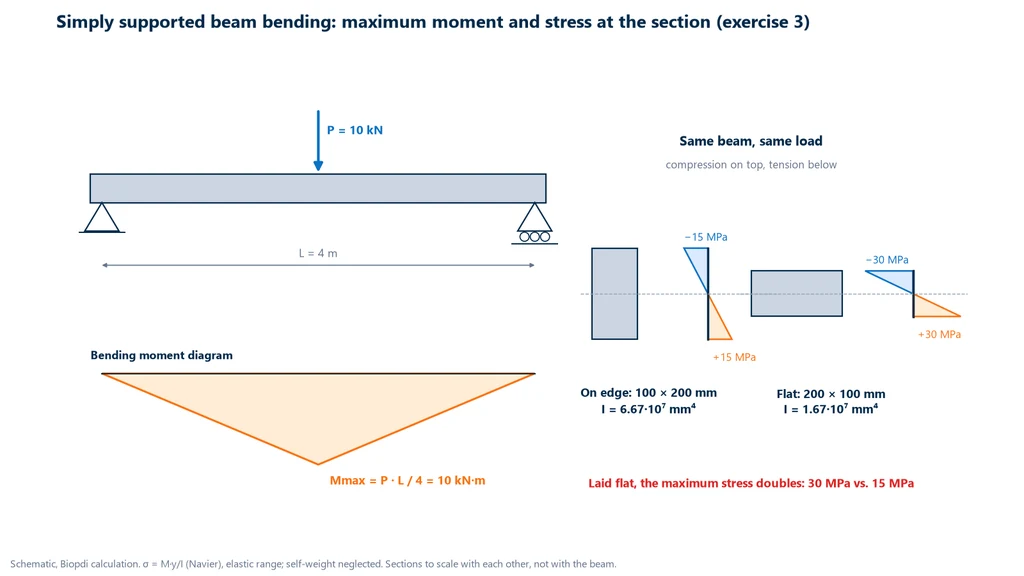
Answer: 15.0 MPa upright (compression at the top, tension at the bottom) and 30.0 MPa lying flat. The same member, with the same area, works at twice the stress when lying flat, because the maximum stress in a rectangle decreases with the square of the depth. The shear stress, 0.375 MPa, is small compared with the bending stress, which is typical of a long beam.
Problem 4: torsion of a solid shaft
A solid steel shaft, 40 mm in diameter and 1 m long, transmits a torque of 1.2 kN·m. What is the maximum shear stress and the angle of twist between its ends?
- Polar moment of inertia: J = π · d⁴ / 32 = π × 40⁴ / 32 = 251,327 mm⁴; outer radius r = 20 mm.
- Maximum stress: τ = T · r / J = 1.2 · 106 × 20 / 251,327 = 95.5 MPa. Check: 16 T / (π d³) = 16 × 1.2 · 106 / (π × 40³) = 95.5 MPa.
- Angle of twist: φ = T · L / (G · J) = 1.2 · 106 × 1,000 / (77,000 × 251,327) = 0.0620 rad.
- In degrees: 0.0620 × 180 / π = 3.55°.
Answer: τmáx ≈ 95.5 MPa at the surface and φ ≈ 3.55° per meter. At the center of the shaft the stress is zero, and 10 mm from the center it is half, 47.7 MPa. If the design limits the twist to, say, 1° per meter, this shaft meets the stress requirement but not the stiffness requirement, and needs a larger diameter.
Problem 5: Euler buckling and validity check
A solid steel bar, 30 mm in diameter and 2 m long, is loaded in compression with both ends pinned (K = 1). With E = 200 GPa and σe = 250 MPa, what is the critical buckling load? Is it valid? How does it compare with the load that would crush the section?
- Geometry: I = π · d⁴ / 64 = π × 30⁴ / 64 = 39,761 mm⁴; A = π × 30² / 4 = 706.86 mm²; r = √(I / A) = d / 4 = 7.5 mm.
- Slenderness: K · L / r = 1 × 2,000 / 7.5 = 266.7, far above the limit of about 89 calculated in the buckling section.
- Critical load: Pcr = π² × 200,000 × 39,761 / 2,000² = 19,621 N ≈ 19.6 kN.
- Validity: σcr = 19,621 / 706.86 = 27.8 MPa, well below 250 MPa, so the Euler formula applies.
- Crushing: σe · A = 250 × 706.86 = 176,715 N ≈ 176.7 kN.
Answer: Pcr ≈ 19.6 kN, about 9 times less than the 176.7 kN that would yield the section. The bar fails by instability long before the material reaches its limit. With both ends fixed (K = 0.5), the critical load rises to 78.5 kN, still below the crushing load, and the slenderness, 133.3, is still in the Euler range. Replacing the steel with a higher-yield grade changes none of these numbers: what increases the critical load is reducing the effective length or increasing the moment of inertia.
Common mistakes and limits of validity
Most mistakes in strength of materials are not in the formula but in using it outside its assumptions or with mixed units. The most frequent ones, in exams and in design:
- Mixing units. Force in kN with area in mm² gives kN/mm², a thousand times the MPa. Rule of thumb: force in N, length in mm, stress and E in MPa (200 GPa = 200,000 MPa), moment in N·mm.
- Confusing the subject with the property. The subject does the calculation; mechanical strength is the material property that goes into it.
- Using Hooke's law beyond yielding. σ = E · ε only holds in the linear region; beyond it, strain grows much faster than stress and the calculated displacement comes out too small.
- Applying τ = T · r / J to a non-circular section. Rectangular bars and open sections warp and require a different theory.
- Assuming a stronger steel buckles less. The Euler load depends on E and on the geometry, not on σe.
- Applying Euler to a short column. If σcr exceeds the proportional limit, the formula overestimates the load; the slenderness must be checked.
- Taking τ = V / A as the maximum stress in a beam. It is the average; in a rectangle, the maximum is 1.5 times larger.
- Using the moment of inertia about the wrong axis. In bending, use I about the axis the beam bends around; in buckling, use the minimum I of the section.
- Giving a factor of safety without stating which limit it refers to. n against σe and against σr are different numbers, as Problem 1 shows.
- Forgetting stress concentration. σ = N / A is the average away from holes, notches and sharp corners; next to them, the local stress is several times higher, and that is where cracks start.
- Using static formulas for cyclic loading or high temperature. A part loaded millions of times fails below yield, by fatigue; under constant load at high temperature, it deforms over time, by creep.
- Reading engineering stress as true stress after necking. The conventional diagram divides by the original area; when the specimen thins down during necking, the curve drops, but the true stress keeps rising.
Strength of materials textbooks
Three textbooks dominate strength of materials syllabi in Brazil, all with theory, worked examples and hundreds of problems. The editions below (Brazilian Portuguese translations) were checked on October 7, 2026 in the publishers' catalogs or in a university library:
| Book | Edition checked | Best suited for |
|---|---|---|
| R. C. Hibbeler, Resistência dos materiais (Mechanics of Materials) | 10th ed., Pearson, 2018 (ISBN 978-85-430-2499-8), 768 pp. | Theory with illustrative examples and problems at several levels of difficulty, in SI units |
| F. P. Beer, E. R. Johnston Jr., J. T. DeWolf and D. F. Mazurek, Mecânica dos materiais (Mechanics of Materials) | 8th ed., AMGH (Grupo A), 2021, 864 pp. | Principles in simple contexts, always with an application, and extensive use of diagrams |
| J. M. Gere and B. J. Goodno, Mecânica dos materiais (Mechanics of Materials) | Cengage Learning, 2010 (translation of the 7th US edition) | Extensive text (858 pages), a complete alternative to the other two |
For the history of the subject, the reference is History of Strength of Materials, by Stephen Timoshenko (McGraw-Hill, 1953). As a free complement, the Strength of Materials I course notes from UFJF (Federal University of Juiz de Fora, in Portuguese) are openly available online and cover the entire first course, with problems for each chapter. Older editions of the books are still in circulation and are fine for studying, but problem numbering changes from one edition to the next: when in doubt, use the edition your instructor recommends.
Where the numbers are measured: the universal testing machine
Strength of materials formulas describe the material with three numbers, E, σe and σr, and these numbers are measured on a universal testing machine (UTM). It applies force at a controlled rate, measures force with a load cell and, with an extensometer attached to the test specimen, measures strain with the accuracy that the modulus and the 0.2% offset yield strength require. By swapping the grips for other fixtures, the same machine reproduces the loads of the course in the lab: tension and compression, three- or four-point bending, and shear of bolts and pins. Each formula therefore has a corresponding test:
| Course formula | Test that provides the data | Article |
|---|---|---|
| σ = N / A, δ = N L / (E A), σadm = σe / n | Tension: E, σe and σr | tensile test |
| Compression of a short member | Compression | compression test |
| σ = M · y / I | 3- or 4-point bending | flexural test |
| τ = V / A | Shear of pins, bolts and joints | shear test |
| τ = T · r / J, φ = T L / (G J) | Torsion: torque, angle and G | torsion test |
Biopdi manufactures the M2 line universal testing machine, from 200 N to 1,000 kN, with class 1 load cells per ISO 7500-1:2023 (ABNT NBR ISO 7500-1:2023 in Brazil), clip-on extensometers and the BioLab software, which plots the curve and calculates the modulus, the yield strength and the ultimate tensile strength. For torsion, Biopdi offers the torsion testing machine, with capacities of 1, 5 and 10 N·m (others on request) and specimens with diameters from 1 to 8 mm and from 5 to 20 mm, and the universal testing machine can be fitted with a torsion module combined with tension, on request. The panel below shows the M2 universal testing machine, the role of each part in the measurement and the fixtures that reproduce the loads of the course:
The universal testing machine in the measurement of E, σe and σr
The M2 line has single-column models, from 200 N to 10 kN, and dual-column models, from 5 kN to 1,000 kN. Each part of the machine handles one step of the measurement:

- Moving crosshead applies tension, compression or bending at the rate set by the standard
- Load cell measures the force F, class 1 per ISO 7500-1:2023
- Grips and fixtures for tension, compression, bending and shear
- Clip-on extensometer measures ΔL over an L0 of 25 to 100 mm, the basis for E and the 0.2% offset yield strength
- BioLab software converts to σ and ε and calculates E, σe and σr
- Control panel and emergency stop position the crosshead and stop the test
Fixtures for the loads of the course
The fixtures below are mounted on the same machine, depending on the specimen and the standard:
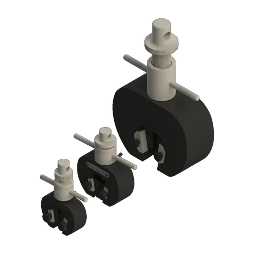 Wedge griptension; 5, 20 and 200 kN
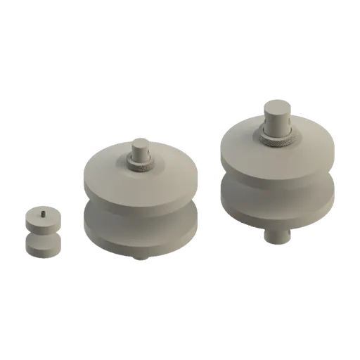 Compression platens1, 50 and 300 kN
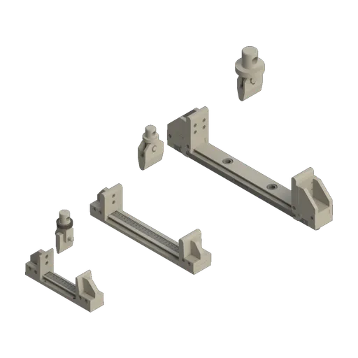 Bending fixture3 and 4 points; 10, 50 and 300 kN
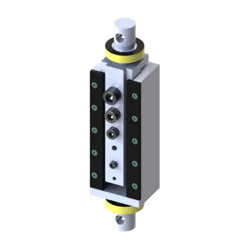 Bolt shearbolts and pins
In a teaching lab, the same machine serves both ends of the subject: it measures the properties that go into the formulas and lets students verify the formulas themselves, by loading a beam in bending and comparing the measured deflection with the calculated one, as in the photo at the beginning of this article.
Conclusion
Strength of materials is the subject that takes you from equilibrium to the dimensions of a part: the method of sections gives the internal forces, the formulas turn each internal force into stress and displacement, and comparison with the allowable stress decides whether the part is adequate. Each formula holds within clear assumptions (elastic material, circular section in torsion, slender column for Euler), and the numbers it uses come from testing. The problems in this article show the three lessons that come up most often in design: a beam works better upright, a slender column fails by instability before the material yields, and a factor of safety only makes sense together with the limit it refers to.
To learn more about each property used here, see the articles on mechanical properties of materials, the stress-strain curve and the modulus of elasticity of steel. To equip a teaching or quality control lab, talk to one of our specialists.
Other tests and technical references
Modulus of elasticity of concrete: NBR 6118 formula, table by strength class and NBR 8522-1 test
The modulus of elasticity of concrete measures how much it shortens under load. Under NBR 6118:2023 (the Brazilian standard for the design of concrete structures), Eci = αE·5600·√fck (C20 to C50) and Ecs = αi·Eci. A C30 concrete with granite aggregate has an Eci of about 31 GPa and an Ecs of 27 GPa. See the formula, the C20 to C90 table, the effect of the aggregate, the NBR 8522-1:2021 test (the Brazilian standard test method for the modulus of elasticity of concrete) and worked examples.
Mechanical properties of materials: what they are, the main types, tests, standards and steel values
The mechanical properties of materials define how a material responds to forces: how much it deforms, whether it returns to its shape, how much load it carries, how much energy it absorbs and how it fractures. See each property with its unit, test and standard, the values for steel (NBR 8800, the Brazilian steel structures design standard; ASTM A36; CA-50, the Brazilian rebar grade), the pairs that are often confused and solved exercises.
Poisson's ratio: what it is, formula, values for steel, concrete and soil, and how to measure it
Poisson's ratio (ν) is the negative ratio of transverse strain to longitudinal strain in a material under uniaxial load in the elastic range. See the formula, its relationship with E, G and K, the range from −1 to 0.5, the values for steel (0.3 per ABNT NBR 8800, the Brazilian steel structures design standard), concrete (0.2 per ABNT NBR 6118, the Brazilian concrete structures design standard), rubber and soils, how to measure it per ASTM E132, and worked examples.
Proportional limit: what it is, how it differs from the elastic limit and yield strength, and how to measure it
In strength of materials, the proportional limit is the highest stress at which stress and strain are still proportional: the end of the straight portion of the curve and of Hooke's law. See the ASTM E6 definition, how it differs from the elastic limit and Rp0.2, how to measure it with an extensometer, and worked examples.
Frequently asked questions
What is strength of materials?
It is the engineering discipline that calculates the stresses and strains caused by loads in deformable parts, so that they can be designed and checked safely. It starts from the internal forces (normal force, shear force, bending moment and torque) and uses properties measured in testing, such as the modulus of elasticity and the yield strength.
What is the difference between statics and strength of materials?
Statics assumes a rigid body and calculates the forces and reactions that keep it in equilibrium. Strength of materials uses those forces to calculate the stresses and strains in the deformable body, which tells you whether the part can withstand the load and how much it deflects.
How do you calculate strength of materials?
First, find the internal forces at the critical section using the method of sections. Then calculate the stress with the formula for that internal force (σ = N / A, σ = M · y / I or τ = T · r / J) and compare it with the allowable stress, σe / n. Example: 50 kN on a 20 mm steel bar gives 159 MPa, below the 167 MPa allowable for A36 steel with n = 1.5.
What is the formula for calculating strength?
The basic formula is normal stress, σ = N / A: the force divided by the cross-sectional area, in MPa when the force is in N and the area in mm². The part withstands the load if this stress stays below the allowable stress of the material, σadm = σe / n. Bending, torsion and buckling have their own formulas, collected in the formula table in this article.
What are the main strength of materials formulas?
The main ones are σ = N / A (normal stress), σ = E · ε (Hooke's law), δ = N · L / (E · A) (elongation), σ = M · y / I (bending), τ = T · r / J and φ = T · L / (G · J) (torsion), Pcr = π² · E · I / (K · L)² (Euler buckling) and σadm = σe / n (allowable stress). All of them apply in the linear elastic range, and the torsion formulas only to circular sections.
What is the best strength of materials textbook?
The most widely adopted in Brazil are Hibbeler, Resistência dos materiais (the Brazilian edition of Mechanics of Materials, 10th ed., Pearson, 2018), Beer, Johnston, DeWolf and Mazurek, Mecânica dos materiais (Mechanics of Materials, 8th ed., AMGH, 2021), and Gere and Goodno, Mecânica dos materiais (Mechanics of Materials, Cengage, 2010). Any of the three covers the whole course. The open-access course notes from UFJF (Federal University of Juiz de Fora, Brazil) are a good free complement.
Is strength of materials difficult?
It is one of the most demanding courses in the first years of engineering, because it combines equilibrium, calculus and section geometry. Engineering education research points to shear stress as one of the hardest concepts for students (Creuziger and Crone, ASEE, 2006). Always working in N, mm and MPa and drawing the free-body diagram before applying any formula avoids most mistakes.
What is the concept of the strength of a material?
The strength of a material is the maximum stress it can withstand before it yields (yield strength, σe) or fractures (ultimate tensile strength, σr). It is a property measured in testing, different from the discipline "strength of materials", which uses this property in calculations. ASTM A36 steel, for example, has a minimum yield strength of 250 MPa and an ultimate tensile strength of 400 to 550 MPa.
Which materials have strength?
Every material has a measurable strength; what changes is the value and the failure mode. Metals such as steel and aluminum are ductile and yield before they fracture; ceramics, glass and concrete are brittle and are much stronger in compression than in tension; polymers and composites behave in ways that depend on temperature and direction. The values for each one come from testing, as shown in the article on the mechanical properties of materials.
Are strength of materials and mechanics of materials the same thing?
Yes, they are two names for the same discipline. "Mechanics of materials" is the title of the textbooks by Beer and Johnston and by Gere and Goodno (Mecânica dos materiais in Portuguese), and "strength of materials" is the traditional name, "resistência dos materiais" in Portuguese, which is also the Brazilian title of Hibbeler's book.
Where do the values of E and σe used in the calculations come from?
They come from the tensile test on a universal testing machine, according to ISO 6892-1 (ABNT NBR ISO 6892-1:2024 in Brazil) or ASTM E8/E8M-25 for metals. The load cell measures the force, the extensometer measures the elongation and the software calculates the modulus E, the yield strength σe and the ultimate tensile strength σr. For structural steel in design, ABNT NBR 8800 (the Brazilian standard for the design of steel structures) adopts E = 200 GPa.
Where can I find solved strength of materials problems?
This article includes five problems solved step by step, covering tension, shear, bending, torsion and buckling, with the calculations checked. The textbooks by Hibbeler, Beer and Gere have hundreds of worked examples, and the Strength of Materials I course notes from UFJF (Brazil), openly available online as a PDF, include problems for each chapter.