
The shear strength of soil is the highest shear stress a soil can sustain on a plane before it fails. Under the Mohr-Coulomb failure criterion, τf = c' + σ' · tan φ'. Here σ' = σ − u is Terzaghi's effective stress, c' is the effective cohesion and φ' is the effective friction angle. Water in the pores lowers σ', and the strength drops with it.
This value decides whether a slope stays up, how much earth pressure reaches a retaining wall and how much load a footing can take. This guide starts from effective stress and moves on to the Mohr-Coulomb envelope and the Mohr circle. It explains the difference between true and apparent cohesion, where the friction angle comes from, how drained behavior differs from undrained behavior and how peak strength differs from residual strength. It then shows where the parameters enter design and how they are measured. It includes five worked examples, all calculated by Biopdi, and reference values taken from primary sources, with page numbers. We checked the edition and status of the test standards on October 7, 2026.
What is the shear strength of soil
The shear strength of soil is the maximum shear stress that a soil can mobilize along a surface before one part of the soil mass slides over the other. It is a stress, expressed in kPa, and it is not a material constant. It depends on the effective normal stress acting on the plane, on the drainage conditions during loading and on how much the soil has already deformed.
Why soil fails in shear
Soil is a particulate material: mineral grains in contact with each other, with the voids between them filled with water, air or both. As the load increases, the grains rarely break. Instead they slide and roll over each other along a narrow band, and the soil mass separates into two blocks that move relative to each other. This is why soil failure is almost always shear failure, and the strength that matters is the resistance to sliding between grains.
At its core, this sliding is friction: the harder the normal stress presses the grains together, the harder it is to make them slip. The logic is the same as the coefficient of friction between two bodies, with one important difference. In soil, part of the load is carried by the pore water, and that part generates no friction. This is why effective stress plays a central role, as the next section explains.
In metals, bolts and adhesives, shear is a different matter: the material is continuous and its shear strength hardly depends on the normal stress. That case is covered in the article on shear testing of materials.
Where shear strength drives the design
Every structure that rests on soil, cuts into the ground or retains a soil mass depends on shear strength. Typical cases:
- Slopes, cuts and hillsides: a landslide occurs when the shear stress along a surface reaches the available strength;
- Retaining walls and shoring: the earth pressure the soil exerts on the structure depends on the friction angle and the cohesion;
- Shallow and deep foundations: the bearing capacity of a footing and the shaft friction of a pile come from the strength of the surrounding soil;
- Embankments on soft clay and earth dams: stability at the end of construction and in the long term is checked with different parameters, as explained further on;
- Pavements and platforms: compacted soil must carry repeated loads without failing.
In civil engineering, all of these cases are checked the same way: the shear stress imposed by the structure is compared with the available shear strength, and the ratio between the two is the factor of safety.
Effective stress: Terzaghi's principle
Effective stress is the part of the total stress that passes from grain to grain through the solid skeleton of the soil: σ' = σ − u, where σ is the total stress and u is the pore pressure, the pressure of the water in the pores. Terzaghi formulated this principle in 1936, in a paper presented at the 1st International Conference on Soil Mechanics in Cambridge, Massachusetts. He stated it in two parts, paraphrased here. First, the effective stress is the difference between the total stress and the pore pressure. Second, all measurable effects of a change in stress, such as compression, distortion and a change in shear strength, are due exclusively to changes in effective stress.
The second part is the one that matters here. Water has no shear strength. It pushes on the grains equally in all directions, and in doing so it relieves the contact between them. If the pore pressure rises while the total load stays the same, the grains are pressed together less, the available friction drops and the strength falls, even though no new load has been applied. This is why long-term shear strength is written in terms of σ' and not σ. The same principle governs the settlement of saturated clays, the subject of the consolidation test.
How to calculate effective stress
In level ground with water at rest, the vertical effective stress at a point is calculated in three steps:
- Total stress: add up the weight of each layer above the point, σ = Σ γi · hi, using the bulk unit weight above the water table and the saturated unit weight below it;
- Pore pressure: below the water table, with water at rest, u = γw · hw, where γw = 9.81 kN/m³ and hw is the depth of the point below the water table. Above it, u = 0 in the simplest assumption;
- Effective stress: σ' = σ − u.
With flowing water, as in dewatering by pumping or seepage under a dam, the pore pressure is no longer hydrostatic and is obtained from a flow net or from piezometers. The rule σ' = σ − u stays the same.
Example 1: the water table rises and the strength drops
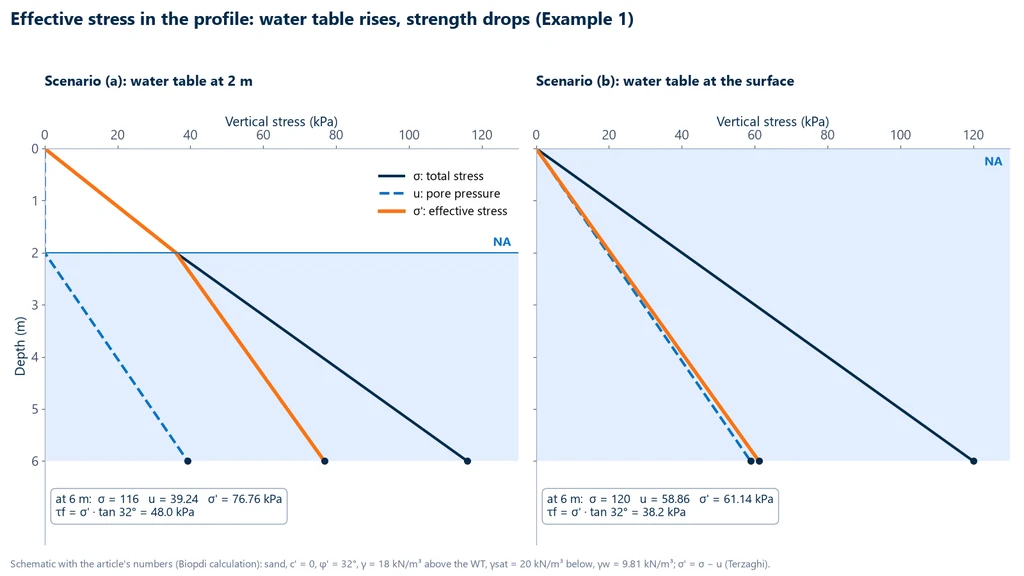
A cohesionless sand (c' = 0) with φ' = 32° has a unit weight of 18 kN/m³ above the water table and 20 kN/m³ when saturated. We calculate the strength on the horizontal plane at a point 6 m deep in two scenarios: (a) water table at 2 m and (b) water table at the ground surface, after a flood. Calculation by Biopdi, with tan 32° = 0.6249:
- (a) Water table at 2 m: σ = 2 × 18 + 4 × 20 = 116 kPa; u = 4 × 9.81 = 39.24 kPa; σ' = 116 − 39.24 = 76.76 kPa; τf = 76.76 × 0.6249 = 48.0 kPa.
- (b) Water table at the surface: σ = 6 × 20 = 120 kPa; u = 6 × 9.81 = 58.86 kPa; σ' = 120 − 58.86 = 61.14 kPa; τf = 61.14 × 0.6249 = 38.2 kPa.
The total stress went up by 4 kPa, because the 0 to 2 m layer became saturated and heavier, but the strength fell by about 20%. The chart below shows the two profiles side by side. The total stress increases almost identically in both scenarios, while in the second one the pore pressure starts higher up and "eats into" the effective stress at every depth.
The reasoning also works in reverse: lowering the water table increases the effective stress and the strength. This is why drains and dewatering are used to stabilize slopes.
What about unsaturated soil?
Above the water table, the pores usually contain both air and water. The water is held at the grain contacts in menisci, at a lower pressure than the air. This pressure difference, called suction (ua − uw), presses the grains together and gives the soil extra strength. Fredlund, Morgenstern and Widger (1978) showed that in this case the strength should be written with two independent stress state variables, the net normal stress (σ − ua) and the suction (ua − uw), instead of a single effective stress. The practical consequence is simple. The part of the strength that comes from suction exists only while the soil is unsaturated, and it disappears when the soil becomes saturated by rain, flooding or a rising water table.
Mohr-Coulomb failure criterion: the strength envelope
The Mohr-Coulomb criterion states that soil fails on a plane when the shear stress on that plane reaches τf = c' + σ'f · tan φ', where σ'f is the effective normal stress on the same plane. On a plot of τ against σ', this equation is a straight line, the failure envelope: c' is the intercept on the τ axis and φ' is the slope.
The criterion has three origins. Coulomb, in 1776, while studying earth pressure on retaining walls, proposed a linear strength with one constant part and another part proportional to the normal stress. Mohr, in 1900, proposed that failure depends only on the major and minor principal stresses and that it occurs when the stress circle touches an envelope, which may be straight or curved. Combining the two ideas, with Coulomb's straight envelope on Mohr's diagram, gives the Mohr-Coulomb criterion (Labuz and Zang, 2012). In soil mechanics, since Terzaghi, the criterion is written in effective stresses, with the prime in c', σ' and φ'.
The table lists the quantities used from here on:
| Symbol | Quantity | Definition | Unit |
|---|---|---|---|
| τf | Shear strength | Shear stress on the failure plane at failure | kPa |
| σ, u, σ' | Total stress, pore pressure, effective stress | σ' = σ − u | kPa |
| c' | Effective cohesion | Intercept of the effective envelope on the τ axis | kPa |
| φ' | Effective friction angle | Slope of the effective envelope | degrees |
| Su | Undrained shear strength | Su = (σ1 − σ3)f / 2, in total stresses | kPa |
| σ'1, σ'3 | Major and minor effective principal stresses | Normal to the planes with no shear stress | kPa |
| θf | Failure plane angle | θf = 45° + φ'/2, measured from the major principal plane | degrees |
Reading the envelope is straightforward. A stress state whose point (σ', τ) lies below the line is stable: the soil mobilizes only part of the available strength. A point on the line is failure. A point above the line cannot exist, because the soil would fail before getting there.
Mohr's circle: formulas
Mohr's circle shows, in a single drawing, the normal and shear stresses on every plane passing through a point. In a triaxial test, or in a soil element loaded only by the principal stresses σ'1 and σ'3, the circle formulas are:
- Center: p' = (σ'1 + σ'3) / 2;
- Radius: R = (σ'1 − σ'3) / 2, which is also the maximum shear stress at the point;
- Stresses on a plane whose normal makes the angle θ with the direction of σ'1 (that is, a plane inclined at θ to the major principal plane): σ'θ = p' + R · cos 2θ and τθ = R · sin 2θ.
When the stress state is given in arbitrary axes, with σx, σy and τxy, the principal stresses come from the same circle: σ1,3 = (σx + σy) / 2 ± √{[(σx − σy) / 2]² + τxy²}. With σx = 120 kPa, σy = 60 kPa and τxy = 40 kPa, for example, the center is 90 kPa, the radius is √(30² + 40²) = 50 kPa and the principal stresses are 140 kPa and 40 kPa.
The envelope tangent to the failure circles
Each specimen taken to failure in a test produces a Mohr circle, with σ'3 and σ'1 at failure. The Mohr-Coulomb envelope is the line tangent to these circles, and the point of tangency gives the stresses on the plane on which the soil failed. The plot below shows three circles for a sand with c' = 0 and φ' = 30°, failed at σ'3 = 50, 100 and 200 kPa, and, beside them, the soil element with the failure plane:
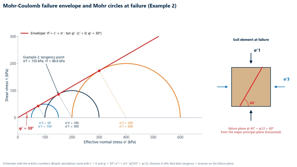
The three circles grow in the same proportion as σ'3: with c' = 0, doubling the confining stress doubles the major principal stress at failure. This is pure friction. With c' greater than zero, the envelope shifts upward parallel to itself, and even the circle with σ'3 = 0, the unconfined compression circle, takes on a finite size.
The failure plane at 45° + φ'/2
The geometry of the tangent circle gives two useful relationships. The first links the principal stresses at failure: σ'1f = σ'3f · tan²(45° + φ'/2) + 2c' · tan(45° + φ'/2). The second gives the inclination of the failure plane: it makes the angle θf = 45° + φ'/2 with the major principal plane. In a triaxial compression test, the major principal plane is horizontal, so the failure plane lies at 45° + φ'/2 from the horizontal.
Example 2: failure plane and the stresses on it. A sand with c' = 0 and φ' = 30° is failed in a drained triaxial test with σ'3 = 100 kPa. Biopdi's calculation:
- σ'1f = 100 × tan² 60° = 100 × 3 = 300 kPa;
- θf = 45° + 30°/2 = 60° from the major principal plane;
- center p' = (300 + 100) / 2 = 200 kPa and radius R = (300 − 100) / 2 = 100 kPa;
- on the failure plane: σ'f = p' − R · sin φ' = 200 − 100 × 0.5 = 150 kPa and τf = R · cos φ' = 100 × 0.866 = 86.6 kPa;
- check with the circle, using θ = 60°: σ'θ = 200 + 100 × cos 120° = 150 kPa and τθ = 100 × sin 120° = 86.6 kPa; and with the envelope, 150 × tan 30° = 86.6 kPa.
Note that the failure plane is not the plane of maximum shear stress. The maximum shear stress, R = 100 kPa, acts at 45°, but there the effective normal stress is 200 kPa and the available strength is 200 × tan 30° = 115.5 kPa: there is spare capacity. The critical plane is the one where the ratio of acting shear stress to strength is highest, and that happens at 45° + φ'/2. In the photo, a clay specimen failed in compression shows this behavior: a single plane inclined at about 60° from the horizontal, with the upper wedge slid over the lower one and a step at the top.
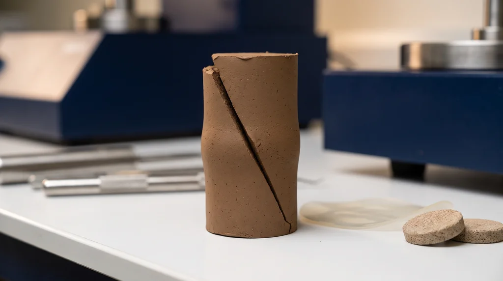
The angle of the visible plane is an indication, not a measurement of φ'. Specimens of loose soil or normally consolidated clay often fail by bulging, with no distinct plane, and in the direct shear test the plane is imposed by the shear box, horizontal, whatever the value of φ'.
Limitations of the criterion
The Mohr-Coulomb criterion is the most widely used failure model in geotechnical engineering because it is simple and has only two parameters, but it has known limitations, summarized in the ISRM suggested method by Labuz and Zang (2012):
- It ignores the intermediate principal stress σ2: failure depends only on σ1 and σ3. Under plane strain conditions, as in a long slope or a continuous wall, the soil may show a strength different from the one measured in a triaxial test;
- The predicted plane does not always appear: the statement that the point of tangency corresponds to the observed failure plane is not always confirmed in tests;
- The real envelope is usually curved: the straight line is a fit that holds over a range of stresses. Extrapolated to stresses much lower or much higher than those tested, it can overestimate the strength.
The practical consequence of the last limitation is the golden rule of testing: specimens should be failed over a range of effective stresses that covers the stresses in the actual project.
Soil cohesion: true, apparent and what is not cohesion
Soil cohesion, in the sense of the Mohr-Coulomb criterion, is the part of the shear strength that exists even at zero effective normal stress: the intercept c' of the envelope on the τ axis. The name suggests a "glue" between particles, and sometimes there is one; but in most tests the intercept has other origins, and confusing them is one of the most expensive mistakes in geotechnical engineering.
The table separates the four cases that go by the name of cohesion:
| What is called cohesion | Physical origin | When it disappears | Where it appears |
|---|---|---|---|
| True cohesion | Cementation between grains by iron and aluminum oxides, carbonates or cement | With weathering, remolding or breakdown of the structure | Cemented residual soils, soil-cement |
| Apparent cohesion from suction | Water menisci between grains in an unsaturated soil | On saturation: rain, flooding, a rising water table | Cuts in dry soil that stand up and collapse in the rain |
| Fitting intercept | Straight line fitted to a curved envelope, in a dense or overconsolidated soil | At low stresses, where the real envelope passes through the origin | A c' of a few kPa in dense sand or overconsolidated clay |
| Su, the "undrained cohesion" | It is not cohesion: it is the total strength of saturated clay without drainage | It changes with drainage and consolidation | Soft clay loaded quickly |
The third case deserves attention because it is the most common. Sørensen and Okkels (2013, p. 2) point out that the effective strength of saturated uncemented clays is frictional and the envelope is nonlinear, so the true envelope passes through the origin and the true cohesion intercept is zero; over the stress range usual in practice, about 50 to 400 kPa, a straight line is fitted, and the c' that appears is an apparent intercept of that line. In normally consolidated clays this intercept is practically zero; in overconsolidated clays it is positive. The test measures the intercept; whether it can be used in design is for the engineer to decide, knowing where it comes from.
In agricultural soil science, cohesion and friction angle are also measured, with the same shear test, to study the effect of management and organic matter on soil structure; this guide covers their use in engineering.
What is a cohesionless soil?
A cohesionless soil is a clean granular soil, such as sand and gravel without fines, whose c' is practically zero and whose strength comes only from friction: τf = σ' · tan φ'. Because the strength is proportional to the effective stress, it is almost zero at the surface, where σ' ≈ 0. That is why dry sand cannot hold a vertical cut and runs down until it forms a slope of limited inclination, and why moist beach sand stands up while suction exists and collapses when it dries out or is flooded.
Cohesive and cohesionless soils
In field language, cohesive soils are clays and plastic silts: they have consistency, can be molded, and under rapid loading respond with their undrained shear strength. Cohesionless, or granular, soils are sands and gravels: they have no plasticity, drain quickly and depend on confinement to resist. The plasticity that separates one group from the other is measured by the Atterberg limits. The classification is useful, but it should not be read as "cohesive soil has a high c'": a normally consolidated clay is cohesive and has a practically zero c' in effective stresses.
Adhesion and cohesion
Cohesion is the strength between particles of the soil itself. Adhesion is the part of the strength at the interface between the soil and another material, such as the shaft of a pile, the back face of a wall or a geosynthetic liner. It is measured in the same type of test, with the structural material in one half of the shear box, and it is generally lower than the soil cohesion, just as the interface friction angle is usually lower than the soil's φ'.
Soil friction angle: friction, interlocking and dilatancy
The soil friction angle, φ', is the slope of the strength envelope in effective stresses: tan φ' tells how much the strength increases for each kPa of effective normal stress. It combines three effects: sliding friction between mineral surfaces; interlocking between grains, which must roll or rearrange to move past one another; and the work of dilation, spent when a dense soil has to increase in volume against the confining stress so that the grains can unlock.
Bolton (1986) separated these components by compiling strength and dilatancy data from 17 sands. At the critical state, where the soil shears at constant volume, the friction angle is mainly a function of mineralogy, about 33° for quartz and 40° for feldspar. In a dense soil the peak angle is higher, and the excess correlates with the rate of dilation, which in turn depends on the relative density and on the mean effective stress: the denser the soil and the lower the confining stress, the higher the peak. This is why φ' is not a fixed number for a given sand: the same sand, compacted or loose, under 50 or 500 kPa, gives different angles.
The factors that increase φ' are well known: angular grains, well-graded particle size distribution, high relative density and low confining stress. In clays, φ' drops as the proportion of platy minerals, which slide more easily, increases, and with it the plasticity index.
Reference values for sands from the SPT
Without a laboratory test, the friction angle of granular soils can be estimated from the SPT blow count for preliminary studies. The geotechnical manual of the Washington State Department of Transportation (WSDOT, Geotechnical Design Manual M 46-03.08, Oct. 2013, Table 5-1, p. 5-13), which adopts a modified correlation from Bowles (1977) as reproduced by AASHTO (2012), gives these ranges for N1,60, the blow count corrected to 60% energy and for vertical stress:
| SPT N1,60 (blows/ft) | Drained φ' (degrees) |
|---|---|
| less than 4 | 25 to 30 |
| 4 | 27 to 32 |
| 10 | 30 to 35 |
| 30 | 35 to 40 |
| 50 | 38 to 43 |
The same manual (p. 5-14) guides the choice within the range: finer materials, materials with a significant silt content or with rounded grains fall in the lower part; coarser materials, with less than 5% fines and angular grains, in the upper part. It also warns that some published correlations use the corrected N and others the field N, and that the designer needs to know which is which; that gravel and cobbles can inflate the blow count; and that no correlation should be extrapolated beyond the range of data from which it was derived. In clays, the SPT does not give φ'.
Reference values for clays from plasticity
For intact overconsolidated clays, Sørensen and Okkels (2013, p. 4), based on triaxial tests from the Danish Geotechnical Institute, proposed correlations between the drained peak φ' and the plasticity index PI, in %. The cautious, lower-bound estimate is φ' = 44 − 14 · log PI for 4 < PI < 50 and φ' = 30 − 6 · log PI for 50 ≤ PI < 150 (equations 5 and 6); the best estimate, from the regression, is φ' = 45 − 14 · log PI and φ' = 26 − 3 · log PI over the same ranges (equations 7 and 8). Applied to four PI values, they give (Biopdi calculation):
| PI (%) | φ' lower bound | φ' best estimate |
|---|---|---|
| 10 | 30.0° | 31.0° |
| 20 | 25.8° | 26.8° |
| 40 | 21.6° | 22.6° |
| 100 | 18.0° | 20.0° |
The authors restrict their use to natural overconsolidated clays with a clay fraction below 80% and warn that, in slopes of highly plastic clay, progressive failure may mobilize less than the estimated peak. In the conclusion of the paper (p. 6), they recommend the correlations as a first approximation for preliminary design and for evaluating test results, and state that the effective strength test is the far more reliable estimate whenever time and cost allow. The plasticity index used in the equations comes from the Atterberg limits. Ranges of φ' by soil class, useful for checking the order of magnitude of a result, are given in the article on the direct shear test.
Friction angle is not the angle of repose or the slope angle
The angle of repose is the slope that a loose, dry granular material assumes when poured into a pile; it is close to the friction angle in the loose state, but it does not represent compacted soil or soil with water. The safe slope angle is a different quantity: it depends on the required factor of safety, the height, the pore pressure and the cohesion. According to the classical infinite slope theory, a slope of dry, cohesionless sand has a factor of safety of 1 when the slope angle reaches φ'; with seepage parallel to the face, the tangent of the slope angle for the same factor of safety drops to about half, because only the submerged weight generates friction.
Sands and clays: drained and undrained behavior
Drained behavior is when water flows out of or into the pores while the soil is loaded, so that no excess pore pressure builds up; undrained behavior is when the load is applied faster than the water can flow out, and the pore pressure changes along with the load. What decides between the two is the relationship between the construction rate and the permeability of the soil.
Sands and gravels are permeable: the pore pressure generated by an embankment or a foundation dissipates in minutes or hours, and the analysis is drained at any time frame, with c' ≈ 0 and φ'. Saturated clays have low permeability: at the end of construction of an embankment, the water has not yet drained, and the analysis is undrained; years later, with the pore pressure dissipated, it becomes drained. The same clay therefore requires two checks. The flowchart below shows the decision path and the test that provides each parameter:

The table summarizes the two analyses:
| Situation | Analysis | Parameters | Tests |
|---|---|---|---|
| Sand, any time frame | Drained, effective stresses | c' ≈ 0 and φ' | Direct shear, CD triaxial |
| Saturated clay, end of construction | Undrained, total stresses | Su, with φu = 0 | UU triaxial, unconfined compression, vane shear |
| Saturated clay, long term | Drained, effective stresses | c' and φ' | CD triaxial, CU with pore pressure measurement, slow direct shear |
Undrained shear strength Su and the φ = 0 condition
In a saturated clay without drainage, increasing the confining stress only increases the pore pressure by the same amount, and the effective stress does not change. That is why, in an unconsolidated undrained (UU) triaxial test, all specimens of the same clay fail at the same deviator stress, whatever σ3 is. In total stresses, the Mohr circles have the same diameter and the envelope is horizontal: φu = 0 and τf = Su = (σ1 − σ3)f / 2.
φu = 0 is a calculation device in total stresses and does not mean that the clay has no friction: in effective stresses, it has a φ' like any soil. For the same reason, Su should not be called cohesion, although the older literature writes it as cu. Su depends on the void ratio and stress history of the clay and changes as the clay consolidates under the load of the structure, which a true cohesion would not do.
Example 4: soft clay in the short term
An undisturbed saturated clay gives, in the unconfined compression test, qu = 80 kPa. We calculate the undrained shear strength, the expected result of a UU test with σ3 = 100 kPa and the undrained bearing capacity of a strip footing resting on the surface. Biopdi calculation:
- Undrained shear strength: Su = qu / 2 = 80 / 2 = 40 kPa, with φu = 0;
- UU test with σ3 = 100 kPa: the deviator stress at failure is the same, 80 kPa, and σ1 = 100 + 80 = 180 kPa; the circle has the same 40 kPa radius, only shifted;
- Short-term bearing capacity: for a strip footing on the surface, with no lateral surcharge, Prandtl's classical theory gives qult = (π + 2) · Su ≈ 5.14 × 40 = 205.6 kPa. The allowable bearing pressure is this value divided by the factor of safety required by the foundation design code applicable to the project.
The unconfined compression test is only valid for cohesive soil that does not lose water during loading; in sand, silt or fissured clay, the result does not represent the soil, as detailed in the article on the triaxial test.
Normally consolidated and overconsolidated clay
A normally consolidated clay has never been under an effective stress greater than the current one; an overconsolidated clay has, due to erosion of overlying layers, a past lowering of the water table or desiccation. The difference shows up in shear. A normally consolidated clay tends to contract when sheared: in an undrained test, this tendency becomes positive pore pressure, the effective stress drops and the undrained shear strength is low, and the effective envelope passes practically through the origin. An overconsolidated clay tends to dilate: in an undrained test, the pore pressure drops, sometimes below zero, the effective stress rises and the peak strength is higher, with a positive intercept c' that, as seen above, is largely an effect of dilatancy. The preconsolidation stress that separates the two states is measured in the consolidation test.
Peak, critical state and residual strength
Peak strength is the highest shear stress that the intact soil reaches; critical state strength is the strength it maintains while it continues to deform at constant volume; residual strength is what remains, in clays, after very large displacements along a single plane. The three are different, and choosing the wrong one is a design error, not a testing error.
Dense sands and overconsolidated clays show a peak: the stress vs. displacement curve rises, reaches a maximum while the soil dilates and then drops to a plateau, the critical state, when dilation is exhausted. Loose sands and normally consolidated clays rise directly to the plateau, without a peak. In plastic clays, if displacement continues, the platy particles align along the shear surface and the strength drops even further, down to the residual.
Residual strength governs surfaces that have already moved: reactivated old landslides, slopes cut in ground with pre-existing failure planes and fissured overconsolidated clays. The WSDOT manual (2013, p. 5-34) recommends that long-term design in the overconsolidated fine-grained deposits of the Seattle area be done with residual parameters, and records that strengths estimated there by back-analysis of landslides and cut slope failures range between 13° and 17°. This is regional data that illustrates the order of magnitude: in plastic clay, the difference between the laboratory peak and the residual can be 10° or more. Measurement of the residual strength, with reversals in the shear box or in ring shear, and typical values by mineral are covered in the article on the direct shear test.
Where c' and φ' enter the design
The strength parameters enter the design in three types of calculation: stability, which compares the available strength with the acting stress; earth pressure, where the mobilized strength defines how hard the soil pushes on a structure; and bearing capacity, where it defines how much load the soil can carry. The table shows how each one uses the parameters:
| Application | How the parameter enters | Note |
|---|---|---|
| Slope stability | FS = available strength / mobilized stress along the failure surface | Short term with Su; long term with c', φ' and the pore pressure |
| Rankine earth pressure | Ka = tan²(45° − φ'/2), Kp = tan²(45° + φ'/2), term −2c'·√Ka | Suction cohesion may disappear with rain |
| Bearing capacity | Factors Nc, Nq and Nγ as functions of φ'; undrained: qult ≈ 5.14 · Su + q | Check both short and long term in clay |
| Numerical models | Mohr-Coulomb as the yield criterion, with c', φ', dilatancy, modulus and Poisson's ratio | Parameters within the stress range of the project |
In numerical models, besides c' and φ', the deformation modulus and Poisson's ratio are needed, and they come from the stress-strain curves of the triaxial test.
Example 3: envelope from three points and local factor of safety
Three specimens of a compacted clayey soil, tested in drained direct shear, failed at the pairs (σ'; τf) = (50; 40), (100; 70) and (200; 130) kPa. Find c' and φ', the strength on a field plane with σ' = 150 kPa, and the local factor of safety if the acting shear stress on that plane is 60 kPa. Biopdi's calculation:
- Slope: tan φ' = (130 − 40) / (200 − 50) = 90 / 150 = 0.60, so φ' = arctan 0.60 = 31.0°;
- Intercept: c' = 40 − 0.60 × 50 = 10 kPa; the middle point checks: 10 + 0.60 × 100 = 70 kPa;
- Strength on the field plane: τf = 10 + 0.60 × 150 = 100 kPa;
- Local factor of safety: FS = 100 / 60 = 1.67;
- The same soil in a triaxial test with σ'3 = 100 kPa: tan(45° + 31.0°/2) = 1.766, and σ'1f = 100 × 1.766² + 2 × 10 × 1.766 = 311.9 + 35.3 = 347.3 kPa.
The three points were chosen to be aligned so the arithmetic stays clean. With real results, which never fall exactly on a straight line, the envelope is obtained by least squares, as in the example in the direct shear test article. The strength this soil offers is not a single number: it is 100 kPa under 150 kPa of effective stress, and it would be different under a different stress.
Example 5: Rankine active earth pressure with cohesion
A 4 m retaining wall holds back a dry soil with γ = 18 kN/m³, c' = 10 kPa and φ' = 30°, with no surcharge. By Rankine's theory, the active horizontal effective stress at a depth z is σ'a = Ka · γ · z − 2c' · √Ka. Biopdi's calculation:
- Active coefficient: Ka = tan²(45° − 15°) = tan² 30° = 0.333, and √Ka = 0.5774;
- At the base, at 4 m: σ'v = 18 × 4 = 72 kPa and σ'a = 0.333 × 72 − 2 × 10 × 0.5774 = 24.0 − 11.55 = 12.45 kPa;
- Depth of the tension crack: σ'a = 0 at z0 = 2c' / (γ · √Ka) = 20 / (18 × 0.5774) = 1.92 m; above it, the calculation gives tension, which the soil does not transmit to the wall;
- Thrust per meter of wall: neglecting the tension, Ea = 0.5 × 12.45 × (4 − 1.92) ≈ 12.9 kN/m;
- If the cohesion comes from suction and vanishes with rain: σ'a = 0.333 × 72 = 24.0 kPa at the base, and Ea = 0.5 × 24.0 × 4 = 48.0 kN/m, almost four times more.
The diagram below compares the two situations: with cohesion, the pressure starts negative, crosses zero at the crack depth and reaches 12.45 kPa at the base; without cohesion, it increases from the surface down to 24.0 kPa.
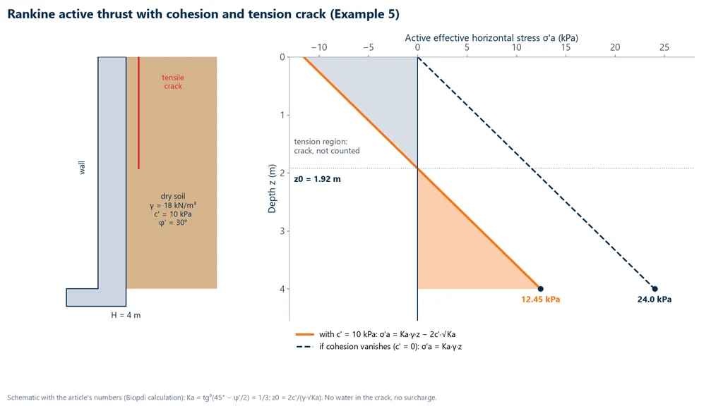
The design lesson is twofold. Cohesion greatly reduces the earth pressure, so the c' used for a wall must come from a cohesion that will last, not from suction. And the tension crack, if it fills with water during rain, starts pushing on the wall with hydrostatic pressure, a load the calculation above did not include.
Why slopes fail after rain
A slope fails after rain because water reduces the strength without a proportional increase in load. Two effects add up. The first is the one in Example 1: infiltration raises the water table or creates a saturated front, the pore pressure rises and the effective stress on the failure plane drops, and with it the σ' · tan φ' term. The second is suction: a cut in unsaturated soil that stood for years at a steep inclination was held up partly by apparent cohesion; when the soil becomes saturated, that term disappears. This is why long-term stability is checked with a c' of known origin and with the pore pressure of the most unfavorable condition, not with the strength measured on a dry day.
How c', φ' and Su are measured
Shear strength parameters are measured by failing soil specimens under controlled stresses in the laboratory, or by shearing the soil in the field. Each test gives one type of parameter, and the choice follows the same drained versus undrained logic as the previous section. The procedure for each one is in the dedicated articles; here we cover what each test delivers.
- Direct shear: the soil, in a split box, is sheared on an imposed horizontal plane under constant normal force, with free drainage. It gives peak c' and φ' and, with reversals, the residual strength. Standard: ASTM D3080/D3080M. Procedure, shear rate and an envelope example in the direct shear test article.
- Triaxial: a cylinder wrapped in a membrane is confined by water under pressure and loaded axially, with controlled drainage and measured pore pressure. The UU test gives Su; the CU test with pore pressure measurement gives total and effective parameters; the CD test gives c' and φ'. Standards: ASTM D2850 (UU), D4767 (CU) and D7181 (CD). Types, calculations and examples in the triaxial test article.
- Unconfined compression: the triaxial case without confinement, σ3 = 0, which gives qu and Su = qu/2 in clays. Standards: ABNT NBR 12770 (the Brazilian standard for unconfined compression of cohesive soils) and ASTM D2166/D2166M. The principle of compression in general is in the compression test article.
- Vane test: a cross-shaped vane pushed into the bottom of a borehole is rotated until the soil shears, and the maximum torque gives the in situ Su of saturated clays, without extracting a sample. Standards: ABNT NBR 10905 (the Brazilian standard for the field vane test) and ASTM D2573/D2573M.
The CBR test, common in the same laboratory, is not on this list: it is an empirical penetration index used in pavement design, and it does not provide c' or φ', as explained in the CBR test article. When the project soil is a fill, the specimens are molded at the moisture content and density of the specified Proctor compaction, because the strength of compacted soil depends on them.
The table summarizes what each test gives and the standards, with the edition and status checked on October 7, 2026: the ASTM standards in the ASTM store (store.astm.org) and the ABNT standards in the Target catalog record.
| Test | What it gives | Standard | Edition and status |
|---|---|---|---|
| Direct shear (CD) | Peak c', φ'; residual with reversals | ASTM D3080/D3080M | D3080/D3080M-23e1, active |
| Triaxial UU | Su (φu = 0) | ASTM D2850 | D2850-26, active |
| Triaxial CU | c, φ, c', φ' and pore pressure | ASTM D4767 | D4767-11, reapproved in 2020, active |
| Triaxial CD | c' and φ', volume change | ASTM D7181 | D7181-20, active |
| Unconfined compression | qu and Su = qu/2 | ABNT NBR 12770 | April 2022 edition, in force |
| Unconfined compression | qu and Su = qu/2 | ASTM D2166/D2166M | D2166/D2166M-24, active |
| In situ vane | Field Su | ABNT NBR 10905 | October 1989 edition, in force, confirmed in August 2023 |
| In situ vane | Field Su | ASTM D2573/D2573M | D2573/D2573M-18, active |
According to the catalog record, NBR 10905 dates from 1989 and was confirmed by ABNT in 2014, 2018 and 2023, with no new edition; the current edition of NBR 12770 was published in April 2022, replacing the 1992 edition. ISO 17892-8, 17892-9 and 17892-10, for triaxial and direct shear testing, are covered in the test articles.
Biopdi equipment for measuring shear strength
Biopdi manufactures the load frames for the two laboratory tests that give c' and φ'. The direct shear apparatus, per ASTM D3080, has a capacity of 10 kN (2,248 lbf), a shear rate from 0.0001 to 20 mm/min, two load cells, LVDTs and 60 and 100 mm shear boxes. The static triaxial load frame is electromechanical, 50 kN, with a speed from 0.001 to 30 mm/min, for UU, CU and CD tests and for unconfined compression. The panel below shows the automatic electric direct shear apparatus and what each part measures in the test:
The direct shear apparatus in the measurement of c' and φ'
The automatic electric version is an electromechanical benchtop unit, microprocessor controlled, with a capacity of 10 kN (2,248 lbf) and two axes driven by recirculating ball screws. Each part has a role in obtaining the envelope:
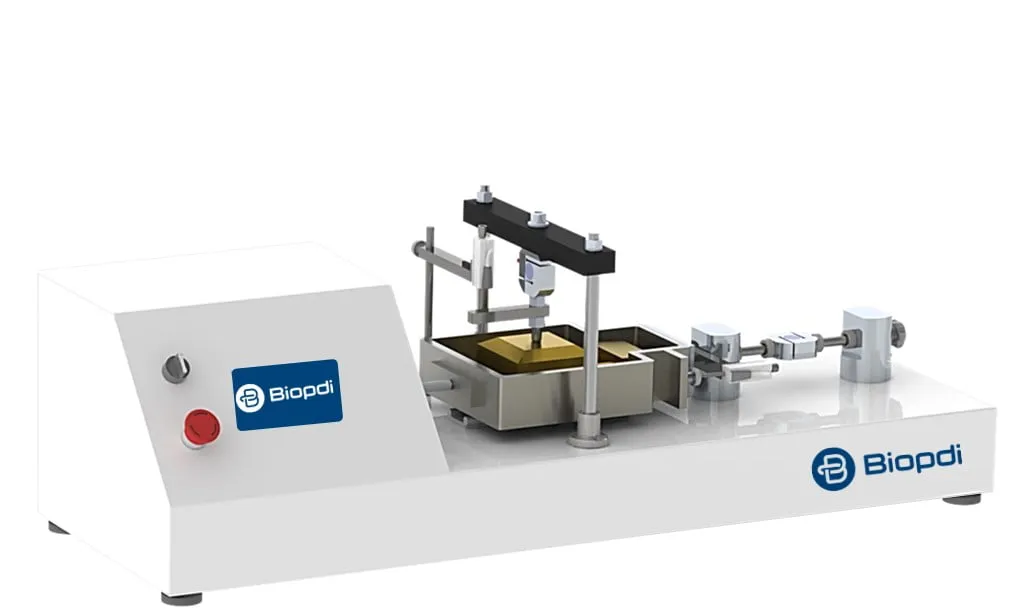
- Vertical axis applies the normal force that defines σ' and keeps it constant, 10 mm stroke
- Horizontal axis moves the box at 0.0001 to 20 mm/min, 20 mm stroke
- Vertical load cell measures the normal force
- Horizontal load cell measures the shear force that gives τ
- Horizontal LVDT, 0.001 mm resolution, measures the shear displacement; the vertical LVDT measures dilation or contraction
- Touchscreen runs the consolidation and shear stages and records the test on an SD card
The slow speed range of the direct shear apparatus covers drained shearing of clays, where the rate is derived from the consolidation time of the specimen itself. The other equipment in the line is on the soil testing equipment page.
Summary of the worked examples
The five examples in this guide cover the most common shear strength calculation questions. The table brings together the data and the answers, all calculated by Biopdi with γw = 9.81 kN/m³:
| Example | Data | Answer |
|---|---|---|
| 1. Water table rises | Sand, φ' = 32°, point at 6 m | τf drops from 48.0 to 38.2 kPa (about −20%) |
| 2. Failure plane | c' = 0, φ' = 30°, σ'3 = 100 kPa | σ'1f = 300 kPa; θf = 60°; σ'f = 150 kPa; τf = 86.6 kPa |
| 3. Envelope and local FS | (50; 40), (100; 70), (200; 130) kPa | c' = 10 kPa; φ' = 31.0°; τf = 100 kPa under σ' = 150 kPa; FS = 1.67 |
| 4. Clay in the short term | qu = 80 kPa | Su = 40 kPa; qult ≈ 205.6 kPa |
| 5. Rankine with cohesion | γ = 18 kN/m³, c' = 10 kPa, φ' = 30°, H = 4 m | z0 = 1.92 m; σ'a = 12.45 kPa at the base; 24.0 kPa without cohesion |
Common mistakes
The most frequent mistakes with soil shear strength are not in the arithmetic, but in the choice of parameter and condition. The ones that show up most in reports, designs and technical pages:
- Using total stress in a long-term analysis. The form τ = c + σ · tan φ, without the prime, is only valid in undrained analysis with total parameters; in the long term, strength depends on σ' = σ − u.
- Treating apparent cohesion as permanent. Suction disappears when the soil becomes saturated, and weak cementation is lost with remolding.
- Calling Su cohesion. Su is undrained total strength, which changes with drainage; φu = 0 is a calculation device.
- Extrapolating the envelope. The straight line is only valid within the tested stress range; at lower stresses, a fitted c' overestimates the strength of shallow slopes.
- Using peak strength where displacement has already occurred. In reactivated landslides and in fissured overconsolidated clays, the design parameter tends toward the residual value.
- Using an SPT correlation as a design value. Correlations are for preliminary studies and for checking tests, and in clays the SPT does not give φ'.
- Expecting the plane at 45° + φ'/2 in every test. In direct shear, the plane is imposed by the box; in the triaxial test, it is not always distinct.
- Confusing the friction angle with the angle of repose or with the safe slope inclination.
- Applying unconfined compression to sand, silt or fissured clay. The test only represents cohesive soil that does not lose water during loading.
- Mixing units. 1 kgf/cm² = 98.07 kPa and 1 tf/m² = 9.81 kPa; older literature and older reports still use both.
Conclusion
The shear strength of soil is friction between grains, governed by effective stress: τf = c' + σ' · tan φ', with σ' = σ − u. This starting point explains why water brings down slopes, why the cohesion measured on a dry day may not be there in the rain, why clays need two checks, short term and long term, and why the same soil has peak, critical state and residual strengths. Reference values help check the order of magnitude, but the design parameter comes from testing, within the stress range and drainage condition of the project.
The procedures are in the direct shear test and triaxial test articles. To equip your laboratory with the load frames for these tests, talk to one of our specialists.
References
The sources cited in the text, with the page when the data comes from a specific page:
- Terzaghi, K. (1936). The shearing resistance of saturated soils and the angle between the planes of shear. Proceedings of the 1st International Conference on Soil Mechanics and Foundation Engineering, Cambridge (MA), vol. 1, pp. 54-56.
- Labuz, J. F.; Zang, A. (2012). Mohr-Coulomb failure criterion. Rock Mechanics and Rock Engineering, 45, pp. 975-979. DOI 10.1007/s00603-012-0281-7. Includes the references to Coulomb (1776) and Mohr (1900).
- Fredlund, D. G.; Morgenstern, N. R.; Widger, R. A. (1978). The shear strength of unsaturated soils. Canadian Geotechnical Journal, 15(3), pp. 313-321. DOI 10.1139/t78-029.
- Bolton, M. D. (1986). The strength and dilatancy of sands. Géotechnique, 36(1), pp. 65-78. DOI 10.1680/geot.1986.36.1.65.
- Sørensen, K. K.; Okkels, N. (2013). Correlation between drained shear strength and plasticity index of undisturbed overconsolidated clays. Proceedings of the 18th International Conference on Soil Mechanics and Geotechnical Engineering, Paris, pp. 2, 4 and 6.
- WSDOT (2013). Geotechnical Design Manual M 46-03.08, ch. 5, Table 5-1 (p. 5-13), p. 5-14 and p. 5-34. Washington State Department of Transportation.
Other tests and technical references
Direct shear test: ASTM D3080 standard, step-by-step procedure and how to calculate c' and φ'
The direct shear test measures soil shear strength and gives the cohesion c' and friction angle φ'. ASTM D3080-23, step by step, with a worked example.
Triaxial test: what it is, UU, CU and CD types, calculations and standards
What the triaxial test is, what the name means, the UU, CU and CD types with their standards, the B parameter, the formulas and worked CU, UU and CD examples.
CBR test and the California Bearing Ratio
CBR test (California Bearing Ratio): NBR 9895:2025 and DNIT 172 standards, procedure, formula with 6.9 and 10.35 MPa, worked example and CBR by layer.
NBR 6457:2024: soil sample preparation and moisture content
ABNT NBR 6457:2024 guide: preparing soil samples for compaction and characterization, masses per test, and oven-dry moisture content with calculation.
Frequently asked questions
What is the shear strength of soil?
It is the maximum shear stress the soil can withstand on a plane before it fails. By the Mohr-Coulomb criterion, τf = c' + σ' · tan φ', where σ' = σ − u is the effective stress, c' the effective cohesion and φ' the effective friction angle. It increases with effective stress and drops when pore pressure rises.
What is the shear strength limit of a soil?
It is not a fixed number for the soil: it is the value of the failure envelope at the effective stress acting on the plane considered. With c' = 10 kPa and φ' = 31.0°, for example, the limit is 100 kPa on a plane with σ' = 150 kPa and would be 70 kPa with σ' = 100 kPa. In saturated clay loaded quickly, the limit is the undrained shear strength Su.
How do you calculate soil strength?
Calculate the total stress on the plane, the pore pressure (u = γw · hw below the water table) and the effective stress σ' = σ − u, then apply τf = c' + σ' · tan φ', with c' and φ' from testing. For saturated clay in the short term, use τf = Su, obtained from a UU triaxial test, an unconfined compression test (Su = qu/2) or a vane shear test.
What is effective stress and how is it calculated?
Effective stress is the portion of the total stress transmitted from grain to grain: σ' = σ − u. It is calculated by adding up the weight of the layers above the point (σ) and subtracting the pore pressure, which for still water is u = 9.81 kN/m³ × the depth below the water table. At 6 m in a sand with the water table at 2 m, for example, σ = 116 kPa, u = 39.24 kPa and σ' = 76.76 kPa.
What does soil cohesion mean?
Cohesion is the portion of shear strength that exists at zero effective normal stress, the intercept c' of the Mohr-Coulomb envelope. It can be true cohesion, from cementation between grains, apparent cohesion, from suction in an unsaturated soil, which disappears when the soil becomes saturated, or merely the intercept of a straight line fitted to a curved envelope.
What is a cohesionless soil?
It is a clean granular soil, such as sand and gravel without fines, with c' practically zero and strength from friction only, τf = σ' · tan φ'. At the surface, where the effective stress is nearly zero, it has almost no strength, which is why it cannot hold a vertical cut.
What are cohesive and cohesionless soils?
Cohesive soils are clays and plastic silts, which have consistency and undrained shear strength under rapid loading. Cohesionless soils are sands and gravels, with no plasticity, which drain quickly and depend on confinement to resist. A cohesive clay can have c' practically zero in terms of effective stress.
What are adhesion and cohesion in soil?
Cohesion is the strength between the particles of the soil itself; adhesion is the strength at the interface between the soil and another material, such as a pile, a wall or a geosynthetic. Adhesion is measured in a direct shear test with the structural material in one half of the shear box, and it is usually lower than the cohesion of the soil.
How do you calculate the friction angle of soil?
Test at least three specimens at different effective stresses, in direct shear or drained triaxial testing, plot the pairs (σ', τf) on a graph and take φ' = arctan of the slope of the line. With (50, 40), (100, 70) and (200, 130) kPa, tan φ' = 90/150 = 0.60 and φ' = 31.0°. For a preliminary study of sands, there are correlations with the SPT, such as Table 5-1 of the WSDOT manual.
What are the Mohr's circle formulas?
The center is (σ1 + σ3)/2 and the radius is (σ1 − σ3)/2. On a plane whose normal makes the angle θ with σ1, the normal stress is center + radius · cos 2θ and the shear stress is radius · sin 2θ. From σx, σy and τxy, the principal stresses are (σx + σy)/2 ± √{[(σx − σy)/2]² + τxy²}.
At what angle does soil fail?
By the Mohr-Coulomb criterion, on a plane at 45° + φ'/2 from the major principal plane: with φ' = 30°, at 60°, which in a triaxial compression test means 60° from the horizontal. In direct shear, the plane is imposed by the shear box, and loose soils may fail by bulging, without a distinct failure plane.
Does the CBR measure the shear strength of soil?
Not directly. The CBR is an empirical penetration index, expressed as a percentage of the response of a standard crushed stone, used in pavement design, and it does not provide c' or φ'. For the strength parameters, the tests are the direct shear test and the triaxial test.