
The direct shear test is a soil mechanics laboratory test that measures the shear strength of a soil. The specimen sits in a split shear box, is consolidated under a constant normal stress and is then sheared slowly under drained conditions to obtain the cohesion c' and the friction angle φ'.
The table gives the quick answer:
| Item | Answer |
|---|---|
| What it measures | drained shear strength of the soil |
| Standard | ASTM D3080/D3080M-23e1, active as of October 5, 2026; there is no Brazilian NBR standard |
| Test specimens | 3 or more, each under a different normal stress |
| Typical stresses | the field stresses; in teaching labs, 50, 100 and 200 kPa |
| Shearing rate | calculated from t50 or t90 of consolidation; without a reliable curve, minimum times to failure of 10 min to 24 h (2011 edition) |
| Result | peak c' and φ'; residual with reversals |
The equipment for the test is on the Biopdi direct shear apparatus page. In detail: the direct shear test is the laboratory test that measures the shear strength of a soil. The consolidated specimen is sheared in a split box, under constant normal stress and at a rate slow enough for drainage, and three or more specimens give the cohesion c' and the friction angle φ'. The reference standard is ASTM D3080/D3080M-23. Each specimen gives a pair of effective normal stress σ' and maximum shear strength τ; with three or more different normal stresses, the line through the points is the Mohr-Coulomb failure envelope, τ = c' + σ'·tan φ': c' is the intercept and φ' the slope.
These two parameters are the design input for the stability of slopes and embankments, the earth pressure on retaining walls and the bearing capacity of foundations. This guide covers the principle of the test, the current standard (and why there is no specific Brazilian NBR standard), the equipment, the step-by-step procedure, the shearing rate rule based on consolidation, the unconsolidated (quick), consolidated quick and slow test modes, the calculations with worked examples checked by hand, how to interpret the curves, peak and residual strength, the comparison with the triaxial test and the most common mistakes.
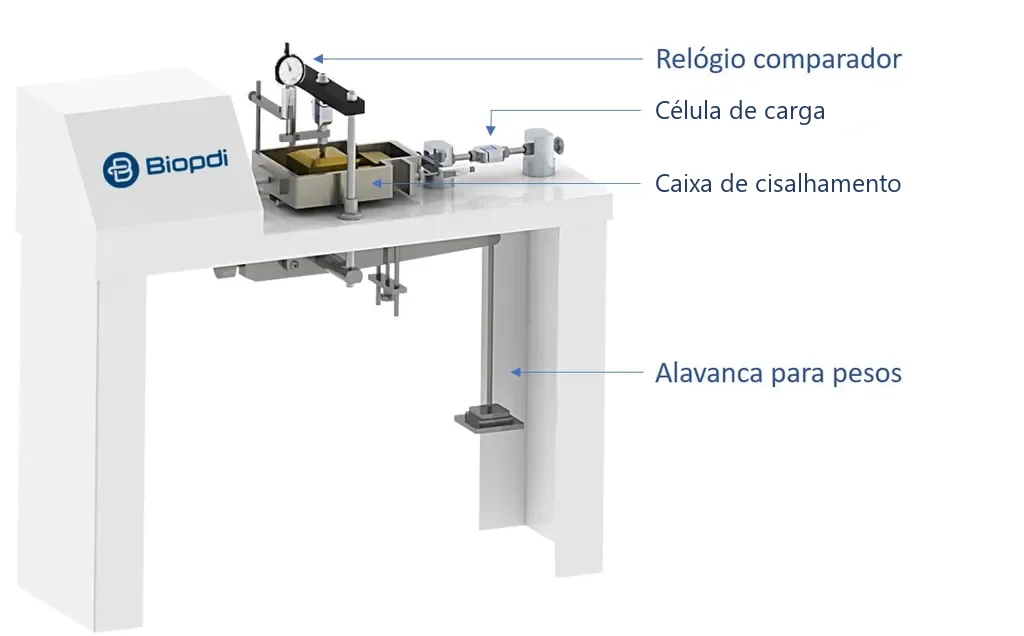
The figure shows the Biopdi lever-type direct shear apparatus: the shear box, holding the soil, sits on the bench, the normal force comes from the weights hung on the lever below, and the shear force is measured by the load cell to the right of the box (in the manual version, this reading is taken on a proving ring). The dial indicator on top measures the change in specimen height during shearing.
What the direct shear test is and what it is used for
The direct shear test (in Portuguese, ensaio de cisalhamento direto; in Portugal, ensaio de corte direto) measures how much shear stress a soil can withstand before failing along a plane. Soil almost never fails in tension or by crushing of the grains. It fails in shear: one mass of soil slides over another along a surface, as happens in a slope that slides, in the soil behind a retaining wall or under a footing that sinks. The resistance the soil offers to this sliding is its shear strength, and the direct shear test is the most direct way to measure it in the laboratory.
The method is old. The first shear box tests recorded in the geotechnical literature are those of Frontard, in 1914, after the failure of the Charmes dam in France, and of Bell, in 1915 (Das and Sobhan, Principles of Geotechnical Engineering). The idea remains the same: force the soil to fail on a known plane and measure how much stress that takes at each level of compression.
In practice, the test is used to:
- obtain c' and φ' for stability analyses of slopes, embankments and dams;
- calculate the earth pressure on retaining structures;
- estimate the bearing capacity of shallow foundations;
- measure the strength of interfaces, such as soil and concrete or soil and geosynthetic, because the fixed failure plane is an advantage when you want to test exactly that surface;
- measure the residual strength of clays in reactivated landslides, with shear reversals.
The same name "shear test" also refers to tests on metals, bolts, rivets and adhesives, carried out on a universal testing machine (UTM) with single or double shear fixtures. Those tests measure something else, the ultimate shear stress of a solid material, and are covered in the article on shear testing of materials. Here the subject is soil only.
Principle of the test: the split box and the Mohr-Coulomb criterion
The principle of the direct shear test is to force the soil to fail on a known plane, under a known normal stress, and to apply the Mohr-Coulomb criterion to the measured stress pairs. The specimen sits in a metal box, square or circular, split horizontally into two halves. A loading plate on top transmits the normal force N, which compresses the soil. After the soil has consolidated under this force, one half of the box is displaced relative to the other at constant rate, and the soil is forced to fail on the horizontal plane between the two halves. During shearing, the test records three quantities: the shear force T, the horizontal displacement between the halves and the change in specimen height.
The diagram below shows the box in cross-section, with the upper half already displaced. The porous stones above and below the soil let water in and out during consolidation and shearing; the small gap between the halves prevents metal-to-metal rubbing that would add friction to the measured force:
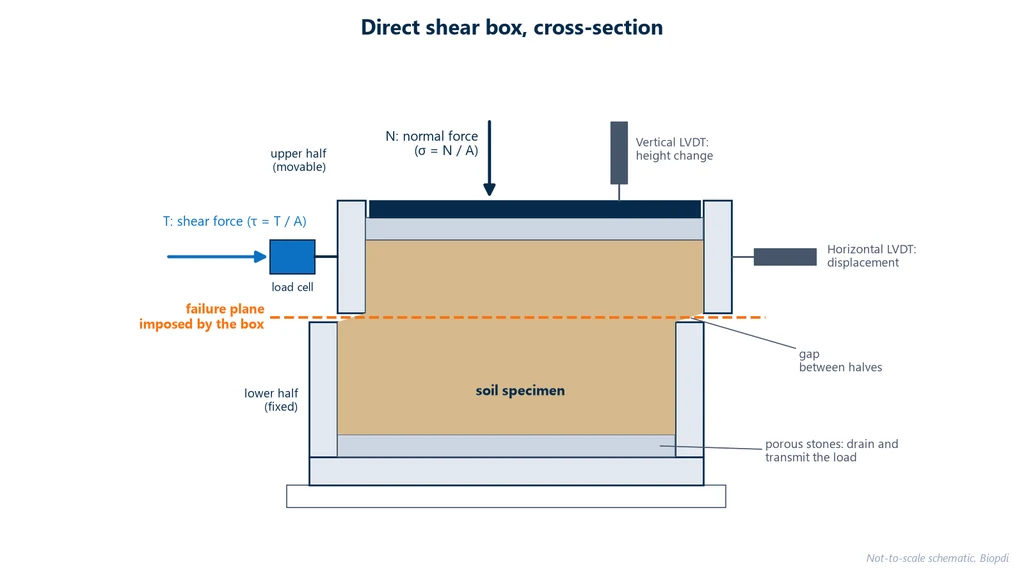
Dividing the forces by the specimen area A gives the normal stress σ = N/A and the shear stress τ = T/A. The strength of the soil has two components, described by the Mohr-Coulomb criterion:
- friction between the grains, which increases with normal stress: the more the soil is compressed, the harder it is for one grain to slide over another. The friction angle φ', also called the angle of internal friction, measures this rate of increase and dominates in sands and gravels;
- cohesion, the component that exists even without normal stress, due to cementation or bonding between particles. It is the intercept c', more relevant in clays and cemented soils.
The prime indicates effective stress. In a saturated soil, the pore water also carries part of the load, and only the part transmitted from grain to grain generates friction: σ' = σ − u, where u is the pore water pressure. Because the test is drained, u remains practically zero during shearing, and the applied normal stress is the effective stress itself. That is why the parameters obtained from the test are effective parameters: c' and φ'.
What standard covers the direct shear test
The standard used in Brazil is ASTM D3080/D3080M-23, Standard Test Method for Direct Shear Test of Soils Under Consolidated Drained Conditions, current as D3080/D3080M-23e1. It replaced the 2011 edition and covers a single specimen per test, recommending three or more, under different normal stresses, to plot the envelope. The title already says the essential: the test is consolidated and drained.
ASTM lists six editions of D3080: -98, -03, -04, -11, -23 and the current -23e1 (checked on the standard's page on October 5, 2026). Anyone still citing D3080-04 is two editions behind. There is also an open revision, work item WK91354, which replaces "engineer" with "qualified professional" in sections 1.4 and 1.5; as of October 5, 2026 it had not been published, and the valid edition remains -23e1.
In Europe, the reference is ISO 17892-10:2018, which describes two drained methods: the shear box, for peak strength, and the ring shear test, for the residual strength of fine-grained soils. The former British standard BS 1377-7:1990 was withdrawn by BSI in 2022, but it is still cited in older course notes and reports.
There is no specific Brazilian NBR standard for direct shear testing of soils. Brazilian university laboratories, such as the Soil Mechanics laboratory at UFOP, state that they follow ASTM D3080 precisely because there is no national procedure in Brazil. The Brazilian standard sometimes associated with the test, ABNT NBR ISO 12957-1, is a geosynthetics standard: it uses the same type of apparatus to measure the friction between a geotextile or geogrid and a standard sand or a soil, and it cannot be used to determine c' and φ' of a soil.
Rock also has its own procedure, which is not D3080. The ASTM standard for direct shear testing of rock specimens under constant normal force was D5607, whose last edition, D5607-16, was withdrawn by ASTM in 2025 with no replacement (status checked on October 1, 2026). For rock joints and discontinuities, the reference still in use is the ISRM suggested method, revised by Muralha et al. (2014, Rock Mechanics and Rock Engineering). The table summarizes the direct shear standards and the status of each:
| Standard | Scope | Status (ASTM and ISO checked on October 1, 2026) |
|---|---|---|
| ASTM D3080/D3080M-23e1 | direct shear of soils, consolidated drained | active (rechecked on October 5, 2026) |
| ISO 17892-10:2018 | direct shear and ring shear of soils, drained | current, confirmed in 2024 |
| ISO 12957-1:2018 | friction of geosynthetics by direct shear | current, confirmed in 2024; not a soil standard |
| ABNT NBR ISO 12957-1 | Brazilian version (2013) of ISO 12957-1:2005, for geosynthetics | canceled without replacement in January 2026 (Target catalog, September 30, 2026) |
| BS 1377-7:1990 | shear strength tests on soils | withdrawn in 2022 |
| ASTM D5607-16 | direct shear of rock, constant normal force | withdrawn in 2025, no replacement |
Equipment and test specimen
The direct shear apparatus combines four functions: applying the normal force, displacing one half of the box at constant rate, measuring the shear force and measuring the displacements. The normal force can come from weights on a lever or from a motor with a load cell; the horizontal displacement comes from a speed-controlled motor; the shear force is measured by a proving ring, on manual machines, or by a load cell; and the displacements by dial indicators or by LVDTs (linear variable differential transformers, electrical displacement transducers).
The box must be made of a corrosion-resistant material, such as stainless steel, bronze or aluminum, with no dissimilar metals in contact that could cause galvanic corrosion. ASTM D3080 sets the minimum dimensions of the test specimen as a function of the largest particle size of the soil (dmax). The values in the table were checked against the full text of the 2011 edition; since dimensions can change between editions, verify them in the current edition, D3080/D3080M-23e1:
| Requirement (ASTM D3080, 2011 edition) | Value |
|---|---|
| diameter or width | ≥ 50 mm and ≥ 10·dmax |
| initial height | ≥ 13 mm and ≥ 6·dmax in the 2011 edition; check the value in the current edition |
| width-to-height ratio | ≥ 2.0 |
| loading plate | 0.25 to 0.5 mm smaller than the box |
| gap between the halves before shearing | about the size of the largest particle; 0.64 mm as the default for fine-grained soils. The current edition states that the gap is specified and that the requester may require a different one |
In practice, the most common laboratory boxes are 60 or 100 mm square (there are also 2 and 4 inch boxes, 50.8 and 101.6 mm), 20 to 25 mm high. Gravelly soils call for large boxes: UFOP, for example, reports 20 × 20 cm and 20 × 40 cm boxes on a 150 kN apparatus. The 10-particle and 6-particle rule exists because a particle that is too large, bearing on the walls or lying across the shear plane, measures the strength of that particle, not of the soil.
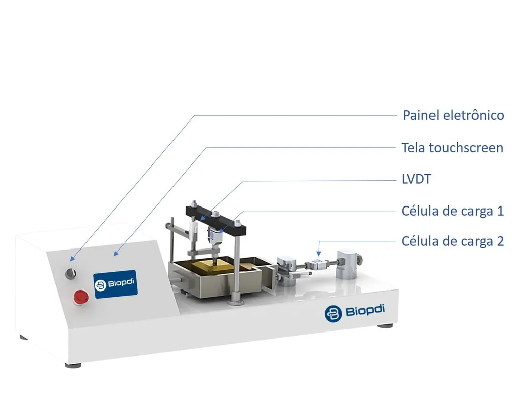
In the automatic version of the Biopdi apparatus, shown below, the normal force and the shear force are applied by motors and measured by two load cells, the LVDT on the loading plate records the change in height, and the test is set up on the panel's touchscreen:
How to perform the direct shear test: step by step
The test has three phases for each specimen: setup, consolidation under the normal stress, and shearing. The sequence below follows ASTM D3080, checked against the full text of the 2011 edition:
- Prepare the specimen (undisturbed, trimmed from a block sample, or compacted at the design moisture content and density) and record its mass, dimensions and initial moisture content. For a remolded specimen, the 2011 edition requires the moistened soil to cure before molding: 3 h for silty sands (SM), 18 h for SC, ML and CL, and 36 h for MH and CH; clean sands need no curing time. The deformation of the apparatus itself under the normal force is calibrated and subtracted.
- Place the specimen in the shear box between the two porous stones, with the box halves locked by the alignment screws, and place the loading plate on top.
- Apply the normal stress selected for that specimen. If the test is run inundated, fill the container with water at this point.
- Consolidate under that stress, recording the specimen height over time until the end of primary consolidation. The height × time curve is interpreted as in the consolidation test (oedometer test), per ASTM D2435/D2435M, and gives the t50 or t90 used to calculate the shear rate. Use the time from the largest normal stress increment applied to the specimen.
- Unlock and open the box: remove the alignment screws and separate the halves to the specified gap using the gap screws. Do not lift the upper half by pulling on the soil.
- Calculate the shear rate from the consolidation data (next section) and start the horizontal displacement at a rate equal to or lower than the calculated one.
- Record the readings of force, horizontal displacement and vertical displacement. During shearing, check that the gap between the halves is maintained; if it closes, stop the test and reopen the box. The standard requires readings at least at 0.1, 0.2, 0.3, 0.4, 0.5, 1, 1.5, 2, 2.5 and 3 mm of displacement and, from then on, at every 2% of the specimen side length or diameter.
- Continue shearing past the peak, to large displacements. The 2011 edition of ASTM D3080 required at least 10% of the side length or diameter; for a 60 mm box, 6 mm of displacement.
- Disassemble by sliding the halves apart along the shear plane, photograph the failure surface and measure the final moisture content.
- Repeat with at least two other specimens of the same soil, under different normal stresses.
The normal stresses should represent the field stresses of the project under study, and that choice is up to the engineer. Course lab procedures commonly use 100, 200 and 300 kPa, or 50, 100 and 200 kPa, as in the worked example further below.
Is the specimen tested inundated or at natural moisture content?
It depends on the design condition, and the choice changes the result. The specimen can be undisturbed, trimmed from a block sample, or compacted at the moisture content and density defined by the designer; in either case, it can be tested inundated, with the container filled from the moment the normal stress is applied, or at natural moisture content. In an unsaturated soil, the suction of the pore water adds an apparent strength component that disappears when the soil becomes saturated. A slope that fails after prolonged rain has lost exactly that component, which is why slope stability analyses usually rely on the inundated test, on the safe side. The test at natural moisture content is suitable for soils that are proven not to become saturated in the field, and the report must state the condition in which the specimen was sheared.
In the shear box, saturation comes only from inundation: there is no membrane or cell to apply back pressure, which is a feature of the triaxial test. Inundation does not guarantee full saturation of a compacted soil; when the project requires verified saturation, the appropriate test is the triaxial test saturated by back pressure.
What to include in the report
The report must allow another engineer to reinterpret the test. The form below gathers the fields, based on the reporting items of ASTM D3080 (section 11 of the 2011 edition) and on the choices this guide asks you to justify:
| Group | What to record |
|---|---|
| soil | identification, USCS class, dmax, whether the specimen is undisturbed, compacted or reconstituted |
| specimen | shear box dimensions, initial height, dry mass, initial and final moisture content, initial density and void ratio |
| condition | inundated or at natural moisture content |
| consolidation | normal force N and stress σ, final settlement and duration of each increment, t50 or t90 with the curve used |
| shearing | shear rate adopted and its justification; readings of T, dh and dv |
| results | τ × dh and dv × dh curves, peak and residual plateau, τmax criterion when there is no peak, area correction used or not |
| failure envelope | c', φ', range of stresses tested and R²; deviations from the procedure |
Shear rate in the direct shear test: t50, t90 and minimum times to failure
The shear rate is the rate of horizontal displacement between the box halves, in mm/min, and it is the parameter that determines whether the test is actually drained. It must be slow enough for water to leave the pores while the soil is sheared, without generating pore pressure. The less permeable the soil, the longer the water takes to drain, and the consolidation stage itself reveals that time. ASTM D3080 first calculates the minimum time to failure, tf (formulas and times in this section checked against the 2011 edition):
- if the height × log(time) consolidation curve is well defined: tf = 50·t50, where t50 is the time to 50% primary consolidation;
- if only the height × √time curve is well defined: tf = 11.6·t90, where t90 is the time to 90% consolidation.
The 50·t50 factor comes from the work of Gibson and Henkel (1954, Géotechnique), who measured the influence of test duration on drained strength. With tf, the maximum shear rate is Rd = df / tf, where df is the estimated horizontal displacement at failure. The 2011 edition specified df = 10 mm for normally consolidated or lightly overconsolidated fine-grained soils and 5 mm for all others; check this value in the current edition before using it.
When the consolidation curves are poorly defined, or the soil is heavily overconsolidated, the standard gives minimum times to failure by soil type, using the Unified Soil Classification System (USCS). The table summarizes these times:
| Soil (USCS) | Minimum time to failure |
|---|---|
| SW, SP (sands with less than 5% fines) | 10 min |
| SW-SM, SP-SM, SM (more than 5% fines) | 60 min |
| SC, ML, CL, SP-SC | 200 min |
| MH, CH (high-plasticity silts and clays) | 24 h |
Example 1: shear rate for a CL clay
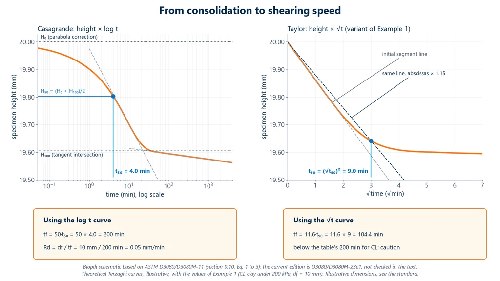
Data: during consolidation under 200 kPa, the height × log(time) curve of a normally consolidated low-plasticity clay (CL) gave t50 = 4.0 min. Take df = 10 mm.
- Time to failure: tf = 50 × 4.0 = 200 min. This matches the table minimum for CL, also 200 min.
- Maximum rate: Rd = 10 mm / 200 min = 0.05 mm/min. Any rate equal to or lower than this is acceptable.
- Variant: if only the √time curve were clear, with t90 = 9 min, the result would be tf = 11.6 × 9 = 104.4 min. This value is well below the 200 min in the table for CL. The standard calls for caution in this case, and adopting 200 min is the laboratory's conservative choice. The standard itself warns that the √time interpretation can yield rates that are too fast, especially in unsaturated or very stiff soils.
The diagram below shows both readings from Example 1 on the consolidation curve. On the left, the t50 of 4.0 min from Casagrande's construction, with specimen height plotted against the logarithm of time. On the right, the variant with t90 of 9 min from Taylor's construction, with height plotted against the square root of time. Note that the square-root-of-time reading leads to a time to failure shorter than the tabulated minimum for CL.
For comparison: a CH clay with no reliable curve requires at least 24 h (1,440 min) to failure; with df = 10 mm, the rate drops to 10/1,440 ≈ 0.007 mm/min. This is why fixed ranges such as "0.01 to 1 mm/min for clays" can be too fast.
Is the test drained or undrained?
The standard test is consolidated drained (CD). ASTM D3080 states in a note that the apparatus is not suitable for undrained tests: the box does not seal the specimen or measure pore pressure, and a fast rate without volume control produces partial drainage to an unknown degree. The former BS 1377-7 said the same: the shear box is only suitable for drained tests.
The effect of the wrong rate is large. Bro, Stewart and Pradel (2013, Geo-Congress, ASCE) tested normally consolidated kaolinite in the shear box at several rates. The ratio of strength to consolidation normal stress dropped from 0.53, in the drained test at 50·t50, to 0.26 in the fastest tests; in a mixture of kaolinite with 20% bentonite, from 0.40 to 0.16. In other words, shearing too fast can cut the result in half without the test "looking" wrong.
Quick, consolidated quick and slow tests: what do they mean?
These are the three traditional variants of the direct shear test, still described in Brazilian course lab procedures and laboratory proposals, and in intent they correspond to the three types of triaxial test. The difference between them is how much time the water is given to drain, before and during shearing. The table compares the three with what actually happens in the box:
| Variant | How it is performed | Intended triaxial equivalent | What happens in the box |
|---|---|---|---|
| quick | sheared right after the normal stress is applied, without waiting for consolidation | UU (unconsolidated undrained) | partial, unknown drainage; not standardized |
| consolidated quick | consolidated under the normal stress and sheared fast | CU (consolidated undrained) | partial, unknown drainage; not standardized |
| slow | consolidated and sheared at the rate calculated from t50 | CD (consolidated drained) | drained; this is the ASTM D3080 test |
In clean sands, which drain in seconds, the three variants give practically the same result, because the water drains even during fast shearing. In clays, the first two give a total stress strength with uncertain drainage, as the tests by Bro, Stewart and Pradel show. The slow test does not need to take weeks: with tf = 50·t50, shearing a CL clay takes a few hours and a CH clay at least 24 h, plus the consolidation time of each specimen.
When the project needs the undrained strength, the appropriate tests are the undrained triaxial test, which controls drainage and measures pore pressure, or the direct simple shear (DSS) test per ASTM D6528-24, which keeps the volume constant.
Direct shear test calculations
The calculations for a direct shear test convert the measured forces into stresses by dividing them by the specimen area, then fit a straight line to the (σ', τmax) pairs from the specimens. At each reading, the nominal stresses are the forces divided by the initial area:
- normal stress: σ = N / A;
- shear stress: τ = T / A;
- relative horizontal displacement: Pd = 100·dh / D (%), where dh is the displacement and D is the side length or diameter;
- average rate: Rd = dh / t.
Each specimen gives one point (σ', τmax). With the n points, the failure envelope is the least-squares line:
- tan φ' = Σ(σi − σ̄)(τi − τ̄) / Σ(σi − σ̄)²;
- c' = τ̄ − σ̄·tan φ', where σ̄ and τ̄ are the means.
Example 0: τ and σ read on a manual machine
On a manual machine, the shear force is not given directly: you read the proving ring dial gauge in divisions and multiply by the ring constant K, T = K·L. Data (teaching example): 50 × 50 mm box, A = 0.0025 m²; normal force N = 250 N; ring constant K = 2.0 N/division (hypothetical value); peak reading L = 95 divisions.
- Normal stress: σ = 250 N / 0.0025 m² = 100,000 Pa = 100 kPa.
- Peak shear force: T = 2.0 × 95 = 190 N.
- Peak shear stress: τ = 190 N / 0.0025 m² = 76,000 Pa = 76 kPa.
This is one (σ', τmax) point of the envelope. The constant K comes from the ring's calibration certificate, not from a catalog.
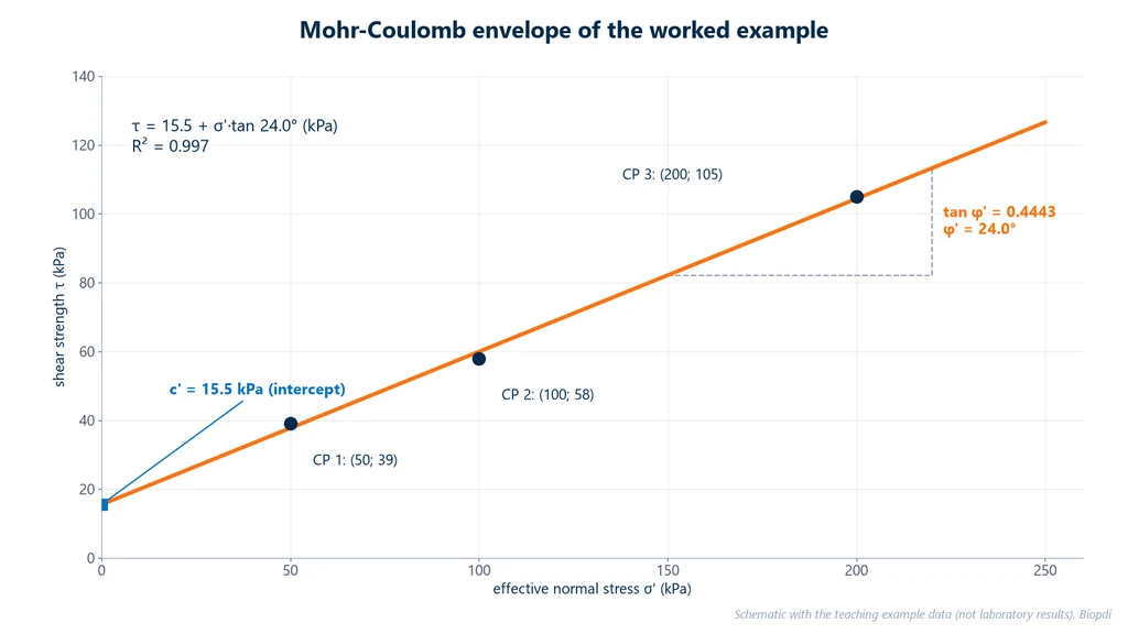
Example 2: failure envelope from three specimens
Data (teaching example, not a laboratory result): 60 × 60 mm square box, A = 0.0036 m², compacted and saturated sandy clay, CD test. Normal forces of 180, 360 and 720 N; maximum shear forces of 140.4, 208.8 and 378.0 N.
- Normal stresses: σ1 = 180 N / 0.0036 m² = 50,000 Pa = 50 kPa; σ2 = 100 kPa; σ3 = 200 kPa.
- Maximum shear stresses: τ1 = 140.4 / 0.0036 = 39 kPa; τ2 = 208.8 / 0.0036 = 58 kPa; τ3 = 378.0 / 0.0036 = 105 kPa.
- Means: σ̄ = (50 + 100 + 200) / 3 = 116.67 kPa; τ̄ = (39 + 58 + 105) / 3 = 67.33 kPa.
- Deviations of σ: −66.67, −16.67 and +83.33. Squares: 4,444.4 + 277.8 + 6,944.4 = 11,666.7.
- Deviations of τ: −28.33, −9.33 and +37.67. Cross products: 1,888.9 + 155.6 + 3,138.9 = 5,183.3.
- Slope: tan φ' = 5,183.3 / 11,666.7 = 0.4443, so φ' = arctan 0.4443 = 24.0°.
- Intercept: c' = 67.33 − 0.4443 × 116.67 = 67.33 − 51.83 = 15.5 kPa.
- Check: the line predicts 37.7, 59.9 and 104.4 kPa at the three stresses; the residuals are 1.3, −1.9 and 0.6 kPa, and the coefficient of determination is R² = 0.997.
Answer: τ = 15.5 + σ'·tan 24.0°, in kPa. The chart below shows the three points and the fitted line, with the intercept c' on the vertical axis and the slope φ':
Example 3: area correction at peak
As the box half moves, the contact area between the two parts of the specimen decreases. In a square box of side L, the corrected area is Ac = L·(L − dh). For the 200 kPa specimen in Example 2, assume the peak occurred at dh = 6 mm:
- Ac = 60 × (60 − 6) = 3,240 mm² = 0.00324 m².
- τc = 378.0 N / 0.00324 m² = 116.7 kPa (nominal: 105 kPa).
- σc = 720 N / 0.00324 m² = 222.2 kPa (nominal: 200 kPa).
- Ratio: 116.7 / 222.2 = 0.525, the same as 105 / 200 = 0.525.
The correction changes both stresses in the same proportion and does not change the τ/σ ratio. ASTM D3080-23e1 itself (section 5.5) notes that the area reduction creates uncertainty about the stresses but should not affect the ratio between them. The standard allows the correction, provided the report states which factor was used and why.
Example 4: can the machine handle the test?
The machine capacity limits the maximum stress that can be applied, and the calculation depends on the box area. Biopdi's automatic electric direct shear machine has a capacity of 1,000 kgf (9.8 kN) for the normal force and 500 kgf (4.9 kN) for the shear force. For a test in a 100 × 100 mm box (A = 0.01 m², or 100 cm², the value entered on the setup screen), with a maximum normal stress of 400 kPa and the soil from Example 2:
- Normal force: N = 400 kPa × 0.01 m² = 4.0 kN = 4,000 / 9.807 = 408 kgf, below 1,000 kgf.
- Expected strength: τ = 15.5 + 400 × 0.4443 = 15.5 + 177.7 = 193.2 kPa.
- Shear force: T = 193.2 × 0.01 = 1.93 kN = 197 kgf, below 500 kgf.
- Rate: the 0.05 mm/min of Example 1 and the roughly 0.007 mm/min for a CH clay are within the machine's range of 0.0001 to 20 mm/min.
With margin on both forces, the load cell can even have a lower capacity, which improves resolution for soft soils.
How to interpret direct shear test results
Interpretation starts with the curves of each specimen and only then moves to the failure envelope. Each question below corresponds to a check the engineer makes on the report.
Did the specimen show a peak?
The τ versus horizontal displacement curve has two typical shapes, shown in the diagram below. Dense or overconsolidated soils rise to a peak and then drop to a plateau; loose or normally consolidated soils rise steadily to the plateau with no defined peak. ASTM D3080 recognizes both shapes and recommends continuing the shear to large displacements, instead of stopping when the force starts to drop, so that the plateau is also recorded:
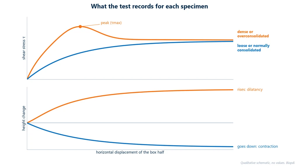
Without a peak, τmax is taken at the plateau or at a displacement criterion defined in the report. This criterion must be the same for all three specimens.
Did the height increase or decrease during shearing?
The lower chart of the diagram explains the peak. In a dense soil, the grains are interlocked and, to slide, they must ride up over one another: the specimen increases in height, a phenomenon called dilatancy. This extra work against the normal stress is what raises the peak. In a loose soil, the grains settle into the voids and the height decreases: this is contraction. The slope of the height curve gives an approximate measure of dilatancy: tan ψ ≈ Δdv / Δdh. If, in a dense sand, the height rises 0.30 mm while the horizontal displacement goes from 2.0 to 3.0 mm, tan ψ ≈ 0.30 / 1.0 = 0.30 and ψ ≈ 16.7°.
What do c' and φ' of the envelope mean?
φ' is the rate at which strength increases with effective stress, and c' is the strength that would remain at zero effective stress. In Example 2, each additional 100 kPa of normal stress adds 44.4 kPa of strength, and the intercept is 15.5 kPa. Both are valid only within the stress range tested: extrapolating the line far below the lowest stress or far above the highest can overestimate strength, because the real envelope is usually curved.
Is a positive c' in sand cohesion?
Generally, no. Clean sands have practically zero c'. A small intercept in a dense sand usually comes from fitting a straight line to a slightly curved envelope, or from the effect of dilatancy at low stresses, not from cementation between grains. Using this c' in design, especially for shallow slopes where the normal stress is low, is unconservative.
Are the values in the expected range?
Before releasing the report, it is worth comparing the φ' obtained with ranges from the literature. They do not replace the test, but they show when something is out of the ordinary, such as a shear rate that is too fast or a disturbed specimen. The compilation on geotechdata.info, which gathers textbooks and standards, gives these ranges (values vary between authors):
| Soil (USCS) | Typical φ' |
|---|---|
| loose sand (SW, SP) | 29° to 30° |
| medium dense sand (SW, SP) | 30° to 36° |
| dense sand (SW, SP) | 36° to 41° |
| silty sand (SM) | 32° to 35° |
| clayey sand (SC) | 30° to 40° |
| low-plasticity silt (ML) | 27° to 41° |
| low-plasticity clay (CL) | 27° to 35° |
| high-plasticity clay (CH) | 17° to 31° |
The φ' = 24.0° of Example 2 is low for a sandy clay and would be at the lower limit of the CL range: in a real case, this would call for checking the shear rate and saturation before accepting the result.
How do the parameters enter the design?
At a point on the failure surface of a slope, with total normal stress σ = 150 kPa and pore pressure u = 30 kPa, the effective stress is σ' = 150 − 30 = 120 kPa. With the parameters from Example 2, the available strength is τ = 15.5 + 120 × 0.4443 = 68.8 kPa. Without pore pressure, it would be 15.5 + 150 × 0.4443 = 82.1 kPa. The difference of 13.3 kPa shows why the parameters must be effective: the water table changes the strength of the same soil.
Peak strength and residual strength
Peak strength is the maximum shear stress the specimen reaches during shearing; residual strength is the stable strength that remains after large displacements on the same plane. Peak strength, τp and φ'p, is used for intact soils with no previous failure surface. In clays, however, strength keeps dropping at very large displacements, because the platy particles align on the shear plane. The final, stable value is the residual strength, φ'r, and it governs reactivated landslides and slopes cut in ground with old failure surfaces.
Skempton (1985, Géotechnique) showed that overconsolidated clays lose strength in two stages: first to the fully softened condition, when dilatancy is exhausted, and then to the residual condition, when the particles become oriented. The residual value depends on the clay fraction and the mineral:
| Condition (Skempton, 1985) | Approximate φ'r |
|---|---|
| clay fraction below about 25% | generally above 20° |
| kaolinite (clay fraction of 50% or more) | about 15° |
| illite | about 10° |
| montmorillonite | about 5° |
The direct shear box reaches the residual condition through reversals: at the end of the stroke, the box half returns to its initial position and the shear is repeated several times on the same plane, often on a pre-cut specimen. The alternative is the ring shear test (ring shear), which rotates the specimen with no displacement limit, following ASTM D6467-21e1 or ISO 17892-10.
Direct shear or triaxial?
The direct shear and triaxial tests measure the same parameters, c' and φ', but direct shear imposes the failure plane and is drained only, while the triaxial test leaves failure free and controls drainage. In the triaxial test, the cylindrical specimen sits in a pressurized cell, enclosed in a membrane, and fails on the weakest plane; drainage is controlled by valves and pore pressure is measured. Hence the three test types: UU (unconsolidated undrained), CU (consolidated undrained) and CD (consolidated drained). In the shear box, drainage is free. The table compares the two tests:
| Aspect | Direct shear | Triaxial |
|---|---|---|
| failure plane | imposed by the box | free, the weakest one |
| drainage | drained only | UU, CU or CD, controlled |
| pore pressure | not measured | measured (CU) |
| stresses on the plane | non-uniform; area decreases | known stress state |
| strain and modulus | not determined | determined |
| duration of drained test | short: short drainage path | long for CD |
| strongest use | interfaces, known weak planes, residual strength | stress paths, undrained conditions |
Direct shear is simpler, cheaper and, for fine-grained soils, faster in the drained test, because water travels only half of the 20 to 25 mm height. It is the natural choice when the problem is drained and the failure plane is known. When the design depends on undrained strength, pore pressure or modulus, the triaxial test is the appropriate one, as UU (ASTM D2850), CU (ASTM D4767) or CD (ASTM D7181). The DSS test, mentioned earlier, sits in between: it shears the whole specimen in simple shear, at constant volume, with no imposed plane.
Common mistakes and limitations
The most common mistakes in the direct shear test involve the shear rate, the specimen size and the reading of the results. Most bad results come from this list, and some of these mistakes are repeated in texts on the subject:
- Citing ABNT NBR ISO 12957-1 as a soil standard. It is the Brazilian adoption of ISO 12957-1, covers geosynthetics and, in addition, was withdrawn in January 2026. For soil, the reference is ASTM D3080.
- Calling the test undrained. The box does not control drainage; a fast test gives parameters with unknown drainage conditions.
- Using a rate from a table without looking at consolidation. A CH clay requires at least 24 h to failure, and 0.05 mm/min may be too fast for it.
- Grains too large for the box. Respect 10·dmax for the width and 6·dmax for the height; gravel goes into a large box. A "5 × 5 mm" specimen, as it appears in some texts, is a unit error: the minimum is 50 mm.
- Referring to back-pressure saturation in the box. The direct shear box has no way of applying back pressure; the specimen is inundated, and verified saturation requires the triaxial test.
- Shearing sand at 1 to 5 mm/min. Even clean sand (SW, SP) requires at least 10 min to failure; with the df of 5 to 10 mm from the 2011 edition, the maximum rate is between 0.5 and 1 mm/min. Sand with more than 5% fines (60 min) drops to 0.08 to 0.17 mm/min.
- Wrong gap between the halves. With no gap, metal-on-metal friction adds to the force; opening the gap by lifting the upper half puts the soil in tension on the shear plane.
- Stopping the test at the peak. Without the plateau, you cannot distinguish peak from residual strength or check the behavior.
- Reading the intercept of a sand as true cohesion. See the interpretation section.
- Calculating modulus or shear strain. ASTM D3080-23 is clear: stresses and displacements are not uniform and the thickness of the failure zone is not defined, so the test gives neither strain nor shear modulus.
- Assuming the imposed plane is the weakest one. In stratified or anisotropic soil, the specimen must be oriented along the plane of interest for the project.
- Testing stiff fissured clay without care. ASTM D3080-23e1 (section 5.4) warns that, in stiff, heavily overconsolidated clays, fissures and discontinuities can cause excessive tilting and vertical movement that invalidate the test.
- Defining friction as a collision force between bodies. In soil, friction is the resistance to sliding between grains, proportional to the effective stress normal to the plane.
The Biopdi direct shear apparatus
Biopdi manufactures the direct shear apparatus in São Carlos (SP), Brazil, in three versions. The manual version has a proving ring and a lever for weights of up to 1,000 kgf (9.8 kN). The semi-automatic version has a load cell, LVDTs, a motor and a touchscreen. The automatic electric version is electromechanical and rated at 10 kN (2,248 lbf), with two load cells, two LVDTs and two motorized axes: one for the normal force and one for the shear force. The shear boxes measure 60 × 60 mm and 100 × 100 mm and are made of brass and stainless steel. The panel below shows the automatic version, the role of each part in the test and the accessories:
The automatic electric apparatus in the direct shear test
The automatic electric version is an electromechanical benchtop unit. It is microprocessor controlled, has a capacity of 10 kN (2,248 lbf) and two axes driven by recirculating ball screws. Each part has a role in the test:
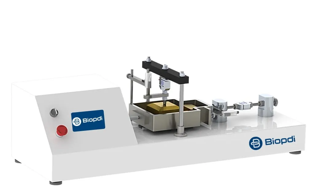
- Vertical axis applies the normal force and holds it at the target stress, 10 mm stroke
- Horizontal axis moves the box at 0.0001 to 20 mm/min, 20 mm stroke
- Vertical load cell measures the normal force
- Horizontal load cell measures the shear force
- Horizontal LVDT, 0.001 mm resolution, measures the shear displacement; the vertical LVDT measures the change in height
- Touchscreen runs the consolidation and shearing stages and saves the test to an SD card
Direct shear accessories
The accessories below are used on the apparatus, depending on the version:
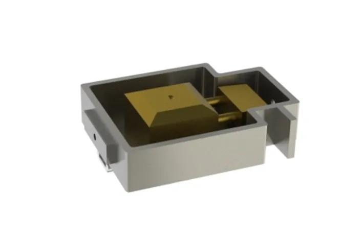 Shear boxsplit, 60 or 100 mm
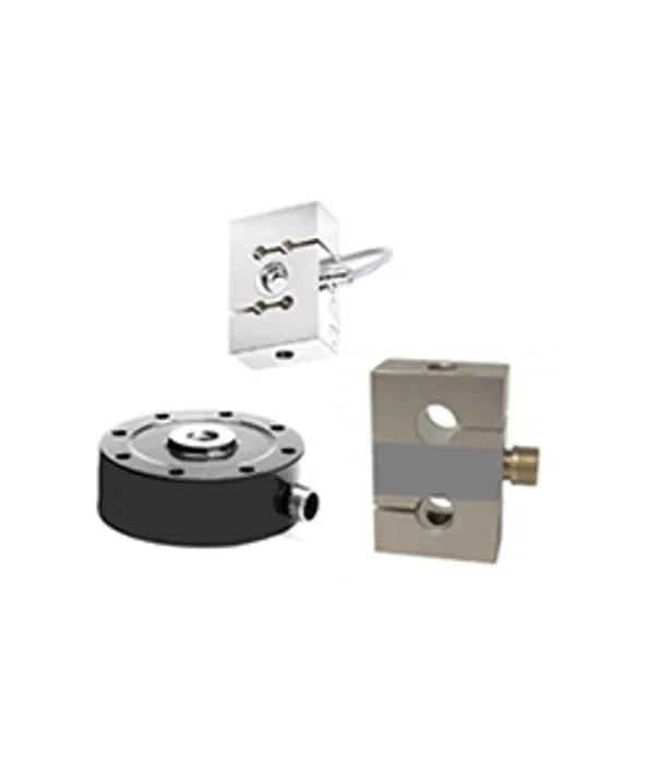 Load cell5 to 1,000 kgf
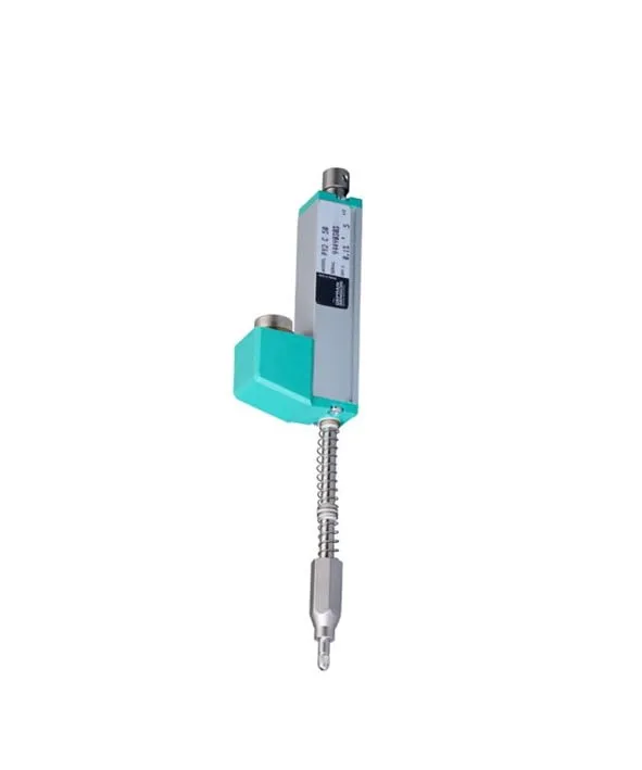 LVDTlinear displacement
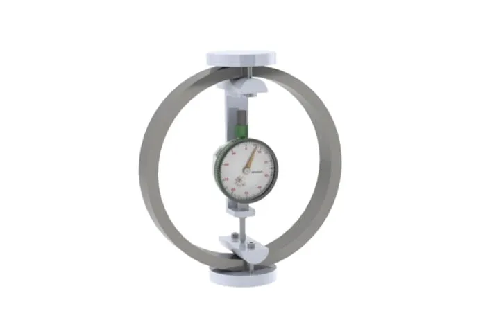 Proving ringmanual version
On the touchscreen, the operator enters the horizontal axis speed in mm/min, the test name, the specimen area in mm² (3,600 to 10,000 mm², for the 60 mm and 100 mm boxes) and the automatic stop criterion, either maximum shear force or maximum horizontal displacement. For the consolidation stage, the operator sets the target stress in kPa, which the apparatus holds constant, and the duration. During shearing, data are acquired at time or displacement intervals. While the specimen is sheared, the screen shows the shear stress and normal stress in kPa, the horizontal and vertical positions and the corrected area in real time. The load cells are interchangeable, from 5 to 1,000 kgf (0.05 to 9.8 kN), so the resolution can be matched to soft or stiff soils. The t50 that sets the shearing rate comes from consolidation, done in the shear box itself or, for the full compressibility curve, in the consolidation apparatus. The Biopdi line of soil testing equipment also includes the triaxial testing system, static and dynamic (the dynamic one is used for resilient modulus testing), and the CBR/Marshall test press, for the CBR and Marshall tests.
Direct shear apparatus video
The video below shows the main features of the Biopdi direct shear apparatus:
Standards cited
The standards cited in this article are listed in the table below. The current editions of the ASTM and ISO standards were checked on October 1, 2026 on the ASTM and ISO websites (D3080 again on October 5, 2026); the status of the ABNT (Brazilian) standards was checked on September 30, 2026 in the Target catalog:
| Standard | Scope | Edition |
|---|---|---|
| ASTM D3080/D3080M | consolidated drained direct shear test of soils | D3080/D3080M-23e1 |
| ISO 17892-10 | direct shear and ring shear tests of soils | 2018, confirmed in 2024 |
| ASTM D2435/D2435M | one-dimensional consolidation (t50 and t90) | D2435/D2435M-25 |
| ASTM D6467 | drained residual strength by ring shear | D6467-21e1 |
| ASTM D6528 | undrained direct simple shear (DSS) | D6528-24 |
| ISO 12957-1 | friction of geosynthetics by direct shear | 2018, confirmed in 2024 |
| ABNT NBR ISO 12957-1 | Brazilian adoption (2013) of ISO 12957-1:2005 | canceled without replacement (January 2026) |
| BS 1377-7 | shear strength of soils (British) | 1990, withdrawn in 2022 |
| ASTM D5607 | direct shear of rock | D5607-16, withdrawn in 2025 with no replacement |
Conclusion
The direct shear test is still the most direct way to obtain c' and φ' of a soil under drained conditions, and it is the first test specified for retaining structures, foundations and slopes. The result is only reliable under three conditions: a shearing rate calculated from consolidation, a specimen size suited to the largest particle, and at least three normal stresses that represent the field conditions. The limitations (an imposed failure plane and no pore pressure control) do not invalidate the method. They define when it is enough and when the problem calls for a triaxial test.
To choose the apparatus and accessories for your laboratory, talk to one of our specialists.
Other tests and technical references
Shear strength of soil: Mohr-Coulomb, cohesion and friction angle
Shear strength of soil: effective stress, the Mohr-Coulomb criterion, cohesion and friction angle, with typical values and 5 worked examples.
Marshall test: stability, flow, Vv, VMA (VAM) and VFA (RBV) per DNIT 447/2024-ME
The Marshall test measures the stability and flow of asphalt mixtures at 60 °C per DNIT 447/2024-ME. Procedure, Vv, VMA, VFA and a worked example.
CBR test and the California Bearing Ratio
CBR test (California Bearing Ratio): NBR 9895:2025 and DNIT 172 standards, procedure, formula with 6.9 and 10.35 MPa, worked example and CBR by layer.
Soil compaction and the Proctor test per ABNT NBR 7182:2025
Soil compaction on site and the Proctor test per NBR 7182:2025: compaction energies, worked curve example, optimum moisture content and degree of compaction.
Frequently asked questions
What is the direct shear test used for?
It measures the drained shear strength of a soil and, with three or more specimens, gives the effective cohesion c' and the effective friction angle φ'. These parameters are used in slope stability analysis, earth pressure on retaining walls and other retaining structures, foundation bearing capacity and dam stability.
What is the standard for the direct shear test?
The reference is ASTM D3080/D3080M-23, current as version -23e1 (checked on October 5, 2026). In Europe, ISO 17892-10:2018 applies. There is no specific Brazilian NBR standard for direct shear of soils, so Brazilian laboratories follow ASTM; ABNT NBR ISO 12957-1 covers geosynthetics and was canceled in January 2026. For rock, ASTM D5607 was withdrawn in 2025 with no replacement.
How does shear work?
A tangential force tries to make one part of the soil slide over the other along a plane. The soil resists through friction between the particles, which increases with the effective normal stress on the plane, and through cohesion, which exists even without normal stress. When the shear stress reaches τ = c' + σ'·tan φ', the soil fails.
What is shear in soil?
It is the failure in which one part of the soil slides over another along a surface, which is how soil almost always fails. Examples of shear failure in soil are a slope slide, soil pushing a retaining wall until it moves, and a footing that sinks while pushing the soil out to the sides; in all of them, the resisting strength is τ = c' + σ'·tan φ'.
What is a shear test?
It is any test that takes a material to failure under shear load. For metals, bolts and adhesives, it is performed on a universal testing machine with shear fixtures; for soils, in the direct shear box or in the triaxial apparatus. The general concept is covered in the article on shear testing of materials.
What is the soil shear test?
It is the laboratory test that measures the shear strength of a soil. In direct shear, the specimen is placed in a split box, consolidated under a constant normal stress and sheared slowly under drained conditions; with three or more specimens, the cohesion c' and the friction angle φ' are obtained. The triaxial test is the other way to measure these parameters.
How does the direct shear test work?
The soil specimen is placed in a split box, receives a constant normal stress and consolidates; then one half of the box is moved relative to the other at a constant rate until the soil fails on the plane between them. The test records the shear force, the horizontal displacement and the change in height, and it is repeated on at least three specimens at different normal stresses.
How is shear calculated in the test?
At each reading, the shear stress is τ = T/A and the normal stress is σ = N/A, where T and N are the forces and A is the specimen area. The point (σ', τmax) of each of the three or more specimens goes into a linear regression: the slope is tan φ' and the intercept is c'. In the example in this article, points at 50, 100 and 200 kPa give c' = 15.5 kPa and φ' = 24.0°.
Is the direct shear test drained or undrained?
The standard test is consolidated and drained (the "slow" test). ASTM D3080 states that the box is not suitable for undrained testing, because it does not control drainage or measure pore pressure; the "quick" and "consolidated quick" tests give an unknown degree of partial drainage. For undrained strength, the appropriate tests are the UU or CU triaxial test and direct simple shear (ASTM D6528).
How is the test rate determined?
From the consolidation curve of the specimen itself: the time to failure is tf = 50·t50 (or 11.6·t90), and the maximum rate is the estimated displacement at failure divided by tf. Without reliable curves, ASTM gives minimum times of 10 min for clean sands, 60 min for silty sands, 200 min for CL, ML and SC soils and 24 h for MH and CH soils.
What is the shearing rate in the direct shear test?
It is calculated, not taken from a table: the maximum rate is the estimated displacement at failure divided by the time to failure, tf = 50·t50 or 11.6·t90. Without a reliable curve, the minimum times of ASTM D3080 (2011 edition) apply, from 10 min for clean sands to 24 h for MH and CH clays. For a clean sand with df of 5 mm, this gives a maximum of 0.5 mm/min.
What size should the specimen be?
In the 2011 edition of ASTM D3080, the width or diameter must be at least 50 mm and 10 times the largest particle, the height at least 13 mm and 6 times the largest particle, and the width-to-height ratio must be 2 or more; check these values in the current edition. Common boxes are 60 or 100 mm square; gravelly soils need large boxes, such as the 20 × 20 cm and 20 × 40 cm boxes at UFOP (Federal University of Ouro Preto, Brazil).
What is the difference between direct shear and triaxial testing?
The direct shear test imposes the failure plane, is drained only and does not measure pore pressure, but it is simple and fast. The triaxial test lets failure develop freely, controls drainage in the UU, CU and CD modes, measures pore pressure and allows strains and modulus to be calculated, which the direct shear box does not.
Is direct shear the same as DSS?
No. Direct shear fails the soil on a plane imposed by the split box, under drained conditions (ASTM D3080). Direct simple shear, or DSS (ASTM D6528-24), deforms the whole specimen in simple shear, usually at constant volume. They are different tests with different equipment.
What is residual strength and how is it measured?
It is the strength that remains after large displacements, when the clay particles align along the shear plane. According to Skempton (1985), it is around 15° for kaolinite, 10° for illite and 5° for montmorillonite. It is measured with reversals in the direct shear box or by ring shear (ASTM D6467, ISO 17892-10).
What is the CBR test?
It is the penetration test that measures the bearing capacity of soils and pavement materials, expressed as a percentage of the resistance of a standard crushed stone. It does not measure c' and φ'; it measures bearing capacity for pavement design, and it is covered in the article on the CBR test.